Autonomous Vehicle Prototype Development and
Navigation using ROS
Nehal Borole1, Dr. R.C. Jaiswal2
1, 2
E&TC Department, Pune Institute of Computer Technology, Pune, Maharashtra, India
Abstract: This paper describes an approach to the development of an autonomous vehicle, which can navigate in indoor environments like warehouses and assembly lines. Specifically, the paper focuses on phases from prototyping the vehicle to developing algorithms for navigation using the ROS framework. Along with the autonomous mode, the vehicle has a semi-autonomous mode through which the vehicle can be controlled remotely using a PlayStation 2 controller connected to the host system. The semi-autonomous relies on a client system (for teleoperation) to which the PlayStation controller is connected. The ROS implementation for autonomous navigation where different nodes come together and work in sync for the task of autonomous navigation will be explained as well.
I. INTRODUCTION
Autonomy has been of utmost importance in places where the roles of humans to handle certain tasks are either risky or time-consuming. From disposing of nuclear waste to search and rescue operations, autonomous robots have played a crucial role. Until now, tremendous progress has been made in the field of autonomous indoor navigation, but some approaches assume the structural parts of the environment to be completely static. The following autonomous vehicle (AV) takes into consideration the dynamic changes in the environment by utilizing sensory data about the environment and vehicle states, and perform localization, dynamic obstacle recognition, and optimal trajectory computation. The AV implementation is carried out in two phases: (1) semi-autonomous mode; (2) semi-autonomous mode.
II. HARDWARE USED A. Nvidia Jetson TK1
B. Kinect sensor
C. Four BS48H motors along with Roboteq SBL1310 motor controller with Hall effect encoders
D. PlayStation 2 Controller
E. PC (client system)
F. Arduino
G. GY-80 Multi sensor board
H. Wireless USB adapter
I. USB to RS232 converter
III. VEHICLE DEVELOPMENT
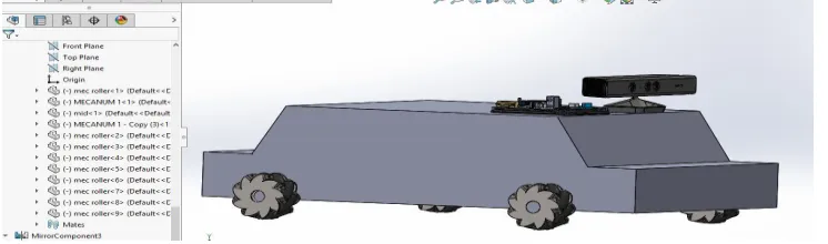
[image:1.612.122.495.607.717.2]As the first step of the AV, the model of the vehicle was developed in Solid Works. The vehicle is fitted with on-board computer and sensors. As a computational platform, Nvidia Jetson TK1 embedded computer has been used, supporting CUDA with on-board parallel computation. The vehicle is mounted with a Kinect sensor, which provides depth images that are helpful to segment objects based on depth rather than intensity. In order to visualize, the vehicle in action in a 3D environment, a ROS package named Rviz is used. Using sw_urdf_exporter plugin in Solid Works a URDF file is generated, which is used by Rviz to generate the vehicle.
Fig 3.2 Model of AV in Rviz with all the links.
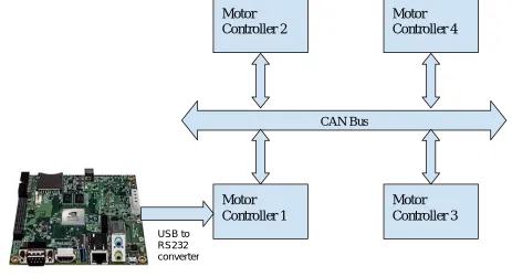
The vehicle in its real-world implementation has four BS48H motors along with Roboteq SBL1310 motor controllers. The controller uses the Hall sensor to compute speed, and measure distance traveled inside a 32-bit counter. These four controllers are connected through RoboCAN, where each controller is assigned an id. Roboteq Linux API is used to interface Roboteq controllers with Ubuntu running on Nvidia Jetson TK1. The hardware connection is established using a serial setup.
Fig 3.3 Motor controllers in CAN architecture.
CAN Bus
Motor
Controller 2
Motor
Controller 1
Motor
Controller 3
Motor
Controller 4
Nvidia Jetson TK1
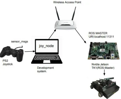
[image:2.612.73.536.447.698.2]IV. SYSTEM ARCHITECTURE AND IMPLEMENTATION A. Semi-Autonomous Navigation
Fig 4.1 System setup for Semi-Autonomous mode.
1) Hardware: For semi-autonomous mode, Nvidia Jetson TK1(host) is connected to the PC(client) over Wifi in the same network. ROS being a network distributed system, multiple devices running ROS can be connected to each other under the same ROS master. In this case, the ROS master is running on Nvidia Jetson TK1. The PS2 controller is connected to the client to teleoperate the AV.
2) ROS Implementation
Fig 4.2 ROS implementation for Semi-Autonomous navigation.
In semi-autonomous mode, a subscription node sub is running on Nvidia Jetson TK1, which has subscribed to messages from joy_node. The sub node, which has code for locomotion of the vehicle, is connected to the motor driver using Roboteq Linux API. The PS2 controller is a USB HID device located at /dev/input/js0 in the Ubuntu root file system. ‘joy_node’ reads the controller’s data, which is published on the topic named sensor_msgs and publishes it to the subscribed topic.
/
joy_node
/
sub
ROS PC
ROS(master)
[image:3.612.111.492.519.654.2]nehal@nehal-Inspiron-5559:~$ rosmsg show sensor_msgs/Joy std_msgs/Header header
uint32 seq time stamp string frame_id float32[] axes int32[] buttons
The actual data from the PS2 controller: ---
header: seq: 9414 stamp:
secs: 1325530130 nsecs: 146351623 frame_id: ''
axes: [-0.0038758506998419762, -0.0038453321903944016, -0.0, -0.999969482421875, 0.0, 0.0] buttons: [0, 0, 0, 0, 0, 0, 0, 0, 0, 0, 0, 0, 0, 0, 0, 0]
---
B. Autonomous Navigation
1) Hardware: GY80 is interfaced with Arduino to get the information of vehicles rotation about the z-axis. Inbuilt encoders with Roboteq controllers are used to calculate speed and distance traveled. Both Arduino and Kinect sensor are connected to Nvidia Jetson TK1, which has ROS master running with various nodes used for navigation autonomously. Rviz, a visualization software, helps to provide start and goal points to the navigation node.
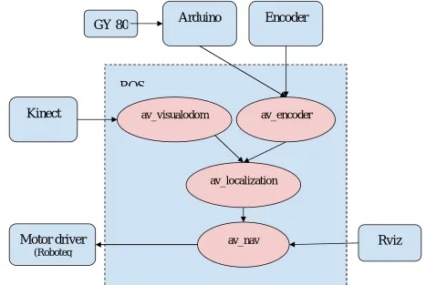
[image:4.612.70.537.394.707.2]2) ROS Implementation
Fig 4.3 ROS implementation for Autonomous navigation.
Kinect
Encoder
av_encoder
av_localization
av_nav
Motor driver
(Roboteq
av_visualodom
Rviz
ROS
In the autonomous mode, the software design follows the ROS structure of special purpose nodes communicating through message passing. As shown in the figure, av_visualodom and av_encoder nodes receive input from the sensors mounted on the AV. The node connected to Arduino and Encoder, av_encoder publishes odometry and angular rotation/heading information to localization node. av_encoder node calculates speed and distance. The odometry data is obtained by translating encoder ticks to distance.
Localization node is responsible to run Monte Carlo algorithms to report current position. It publishes the geometry_msgs/Pose2D message.
Message Message definition
geometry_msgs/Pose2D float64 x float64 y float64 theta
The localization data from av_localization goes to av_nav node which would then send speed and steering values to the motor driver. Notice that the av_nav node is connected to Rviz which publishes the start and endpoint of the path that needs to be traversed. Algorithms related to path planning like A* can be implemented in the node av_nav.
V. CONCLUSION
The Autonomous Vehicle demonstrated in this paper is a complete system, with all the ROS nodes working together as a unit. ROS makes it easier to manage the entire code for making an autonomous vehicle. The modularity helps to unit test various modules to reduce errors. The scope and true potential of ROS cannot be understated. Its implementation makes the intimidating task of developing an autonomous vehicle more achievable.
VI. ACKNOWLEDGEMENT
I would express my gratitude towards my mentor, Dr. R. C. Jaiswal for being constant support and guiding me through the research. He gave this paper the insight and the expertise it needed for making it a presentable one. His advice and encouragement proved to be a valuable guidance.
REFERENCES
[1] Chris Lalancette .,“urdf”,July 2015.URL http://wiki.ros.org/urdf
[2] PS2 Joystick : http://wiki.ros.org/joy/Tutorials/ConfiguringALinuxJoystick
[3] Marder-Eppstein, E., Lu, D. and Hershberger, D., “costmap_2d”, July 2015. URL http://wiki.ros.org/costmap_2d
[4] Lu, D., “global_planner”, July 2015. URL http://wiki.ros.org/global_planner
[5] Marder-Eppstein, E. and Perko, E., “base_local_planner”, July 2015. URL http://wiki.ros.org/base_local_planner
[6] Roboteq Linux API: https://www.roboteq.com/index.php/docman/motor-controllers-documents-and-files/nxtgen-downloads-1/application-programming-interface/348-roboteq-linux-winapi-manual/file
[7] Shengdong Liu, Pulak Sarangi, Quentin Gautier “3D Reconstruction Using Kinect and RGB-D SLAM “