Hypersonic Scram-Jet Engine Inlet Design
P. Nithish Reddy1, R. Sri Preetham Sai2 1
Associate Professor, 2Sreenidhi Institute of Science and Technology, Mechanical Engineering, Hyderabad
Abstract: The present investigation gives a preliminary report of the analysis and design procedure of a scramjet engine mixed compression inlet operating within a Mach number 5 to Mach number 10 range without any moving parts in the Geometry such as the cowl lip, to find an optimal 2D geometry. A basic introduction of Scramjet Engines as well as its first component and the object of interest in present investigation, the Scramjet Engine inlet, is given and different possible number of basic inlet configurations are proposed. The design methodology aims to find an optimal inlet geometry which has maximum TPR (total pressure recovery) at a specific design free stream Mach number and satisfies the shock-on-cowl lip condition. Next, 2D CFD simulations are carried out for some inlet geometries with Mach numbers 6 and above, 7 and above, 10 that are designed based on shock-on-lip condition and gas dynamic relations. The K-Omega SST turbulence model in Fluent is used to take into consideration boundary layer phenomena which cannot be considered when investigation is performed in a laboratory. Lastly, a conclusion summarizing the design process is drawn and the optimal model under a certain Mach number is recommended by. Keywords: Scramjet engine mixed compression inlet, Mach number, TPR (Total Pressure Recovery), Shock on Cowl lip Condition, K-Omega SST Turbulence Model.
I. ABBREVIATIONS AND SYMBOLS
1) Shock Wave: Shock waves are highly localized irreversibility in the flow. A shock is said to have occurred if there is an abrupt reduction of velocity in downstream of supersonic flow in passage around body.
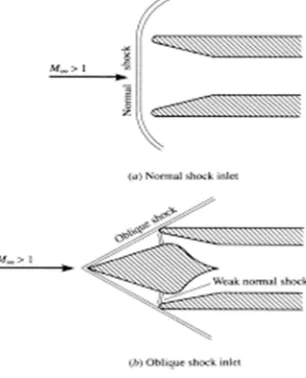
[image:1.612.229.382.390.579.2]2) Oblique Shock Vs Normal Shock: If a Shock wave is perpendicular to the flow direction, it is called a Normal Shock. When a Shock wave is inclined to the flow direction, it is called an Oblique Shock.
Fig 1: Normal and Oblique Shocks
3) Oswatitsch Criterion: To improve the compression efficiency, shocks have to be of equal strength this is called oswatitsch criterion.
4) Kantrowitz Limit: Ratio of area at cowl lip to beginning of isolator is called Kantrowitz limit. Scram-jet inlet unstarts if kantrowitz limit is not satisfied. Inlet unstart might also occur due to formation of separation region. Formation of such a region was observed practically if the Mach number achieved at the beginning of isolator is less than 50% of Free stream Mach Number.
a) Symbols
M = Free Stream Mach number. M = Mach number after shock.
M = Specified Mach number after external compression (0.68M ) θ = Turning angle.
β = Shock angle.
T.P.R = Total Pressure Recovery. S.P.R = Static Pressure Ratio. γ = 1.4 (Specific Heat Ratio of Air).
II. INTRODUCTION
[image:2.612.69.559.443.607.2]Space exploration is the essential part of the human survival, it is important as much as breathing is for our survival and most of the space exploration was made possible because very high speeds which is needed to escape earth’s gravity, for years this was made possible because of rocket engines but cost incurred by the companies and space agencies for rocket engines is very high. Now-a-days space vehicles and satellites are launched using multi stage rocket engine vehicles in most cases these launch vehicles are used only once. These launch vehicles carry fuel which contains 70 percent of oxidizer only and in addition to the fuel they can only carry 2 to 4 percent of their lift off masses to the orbit so, these launch vehicles are very expensive and not very efficient, for this reason research is being carried out to develop air breathing engines to power the launch vehicles which use oxygen in the atmospheric air for combustion loosing their need for oxidizer tanks on board. One such type of air breathing engines are Scram-jet engines, scram-jet engines also known as supersonic combustion ram-jet engines which utilize atmospheric air entering at supersonic speed in to combustion chamber for the purpose of combustion. Scram-jet engine mainly consists of an inlet, isolator, combustor and nozzle. These scram-jet engines use the air entering at hypersonic speed (Mach 5 to Mach 10 range) to decrease it to supersonic speed (Mach 1.2 to Mach 5 range) by means of shock waves before entering the combustion chamber where combustion takes place. The shock waves produced for decreasing the speed is done by the scram-jet inlet our topic of investigation, without the scram-jet inlet the shock waves are not produced and compression of air because of shock waves needed for the combustion also doesn’t take place so, scram-jet inlet is one of the parts in the scram-jet engine and thus requires a through study and research for its design.
Fig 2: Scram-jet Engine
number range for which it is designed. This study aims to tackle this challenge and attempts to design an inlet operating in range of Mach 5 to Mach 10 without the use of varying geometry. In this study, the gas dynamic oblique shockwave relations serve as the theoretical base for inlet analysis. Various inlet design criteria can be found in tests and experiments carried out in past scramjet projects. Notably, powerful Solver tool of Excel and CFD turbulence modelling in Fluent allow us to optimize the performance of the inlet and to capture complex phenomena of the flow through the inlet.
[image:3.612.190.421.221.418.2]A Scram-jet inlet notably has 3 parts 1) Forebody 2) Cowl 3) Isolator. There are basically three types of scram-jet inlets 1) External compression Inlet 2) Internal compression Inlet 3) Mixed compression Inlet. Out of the both external and internal compression inlet designs are not very feasible and reliable. Internal compression inlet being a complicated design which produces complex fluid flow structure and unwanted drag, external compression inlet which requires fluid flow to enter at very large angle with respect to the free stream flow in order to ensure the production of shockwaves, mixed compression inlet was chosen for investigation to obtain benefits of both type of inlets.
Fig 3: Types of Scam-jet Inlet Configurations
III. LITERATURE REVIEW
Scramjet inlet is one of the most important components of the scramjet engine, it enables compression of air without the use of any moving parts such as a compressor. This kind of engine was first implemented in 2004 creator of X-43A, Hyper-X claimed first flight of thrust producing scramjet with full aerodynamic maneuvering surfaces. Some of the previous investigations on scram-jet inlets are presented below.
1) K. Oswatitsch [2] One of the early attempts to design an optimal geometry for the scramjet inlet was done by Oswatitsch. His design reduces the flow velocity to subsonic speed before entering the combustion chamber. By using the gas dynamic relation and Lagrange multipliers by using gas dynamic relations mentioned in this paper and Lagrange multipliers, with an objective of maximum total pressure recovery after the compression process, a set of oblique shock angles and one terminating normal shock angle after which the flow turns sonic were obtained. It has been observed that in order to improve the efficiency of combustion, oblique shocks generated must be of equal strength (Oswatitsch criterion).
2) M. K. Smart [3][4] has done further investigation on scramjet inlets, where the inlet was optimized based on maximum total pressure recovery and Oswatitsch criterion is also observed. In his investigation It is also found that total pressure recovery increases with an increase in number of shocks. Later in his other thesis smart depicts that inlet configuration chosen for scramjet engine is dominating feature of the entire flow path and it also depends on requirements of the engine, with emphasis on the method of integration with the vehicle and the operation range of Mach number over the proposed flight trajectory. He also recommends the compression level of required for scramjet inlets as to set the inlet compression ratio to the minimum so that it enables the combustion to be completed in the length scale of the engine combustor. However, this recommendation is supplemented by the caveat that the compression ratio never to be below 50, in order to maintain high cycle efficiency.
4) M. K. Smart and C. A. Trexler [6] proposed that scramjet inlet unstart is also caused due to presence of separation layer in the flow.
5) J. M. Delery [7] proposed that Mach number at the beginning of the isolator is an important parameter that influences the formation of separation region in the scramjet inlet.
6) J. J. Mahoney [8] in his experiments observed that separation region in the scramjet inlets are formed if Mach number at the beginning of the isolator is less than 50 percent of the free stream Mach number. He also proposed that when separation layers are unavoidable various remedies such as bleeding and blowing of inlet must be done to control or reduce the influence of separation region on the inlet.
7) N. Om Prakash Raj and K. Venkatasubbaiah [9] developed a method to design scramjet inlet which combines both maximizing pressure recovery and obtaining a prescribed Mach number at beginning of the isolator criteria to obtain an optimal inlet geometry. They also noticed a significant deviation in the inlet performance parameters on performing a 1D, 2D inviscid and viscous analysis. Their results depict that 2D and Viscous effects must be considered for scramjet inlet design. They stated that shock-on-lip condition is only imposed by the design methodology and is not satisfied in the viscous flow field condition due to shock-shock and shock/boundary layer interaction, for that they provided a correction equation which gives actual Mach number that satisfies the shock-on-lip condition. Their predicted results agree with the experimental results in their literature. 8) Sarah Frauholz, Marek Behr, Birgit U. Reinartz and Siegfried Muller [10] Proposed the advantages of the mesh adaptive
computations compared to the structured grid computations for a scramjet engine inlet. The results obtained by them in case of mesh adaptive simulations are as accurate as well-validated results obtained for structured computations. Adaptive grids contain fewer cells compared to structured grids and due to this the computational costs are reduced and computation speed is at least twice as fast compared to the structured grids. They also mentioned that it is not needed to pre refine the grids in areas of interest in flow direction for adaptive grids, which is necessary in case of structured grids. Pre refinement makes the flow dependent on grid which influences the results, however sometimes to resolve boundary layers near the wall in normal direction a-priori grid refinement will be needed. Adaptive grids are very helpful for users with little experience in meshing as resolving of the grid is done automatically.
The present investigation aims to obtain the optimal geometry for Scram-jet engines with 2 external and 2 internal ramps. The Objective of this project is to design a mixed compression inlet by intuitively combining two methodologies: 1) obtain maximum pressure recovery after whole compression process, 2) to get a specified Mach number at beginning of the isolator. The shock on lip condition is a case where all the oblique shock waves from different ramps meet at cowl point which in turn enables internal compression process in the isolator. These shock on lip condition ensures maximum total pressure recovery at a prescribed free stream Mach number. The shock on lip condition is essential for successful working of the design as it ensures maximum capture area and minimum intake length. More over the ramp angles were calculated from custom written c-program as per the design criteria.
IV. DESIGN METHODOLOGY
A. Design Calculations
The design of inlet is done for specific free stream Mach number ( ). So, designer must first choose a Mach number for which he/she wants to design.
1) Then assume the value of Static Pressure ratio (SPR), start from the lowest value such as 0.01.
2) After assuming the SPR value find the value of Turning angle (ϴ) also called the ramp angle and then find the Shock angle(β)
from below gas dynamic relations.
= [
( − ) + +
]
= [ ( −
( + + ))]
3) Then after finding the ramp angles and shock angles find the Mach number ( ) and Total Pressure Ratio after the shock using below relations.
4) The SPR Value for the next shock will be same as the before shock SPR value.
= ( ) + − − ( )− ( − ) = [ + − + + ( )− + − ]
5) The Mach number after final external compression is called as it is basically taken as 68 percent of free stream Mach number.
6) The Mach number behind last external compression is compared with the Mach number after external compression . 7) If they are equal then the angles obtained for the external ramps are correct.
8) Otherwise, increase the SPR value again and repeat the same process until above mentioned Mach numbers are equal.
9) if the Mach numbers are equal then select the cowl tip position where all the oblique shocks meet. That is the point where shock-on-lip condition occurs which ensures good compression before entering the combustion chamber.
10) For internal compression the SPR of last external shock is considered as SPR for next internal shock.
11) Same Gas dynamic relations are used for internal compression process and the iterative process is performed until Mach number at the beginning of isolator greater than or equal to fifty percent of free stream Mach number.
i.e. = .
12) The no. of ramps, each ramp length, overall inlet is designer’s wish but below conditions must be considered before choosing number of ramps and ramp length.
a) If the Number of shocks increases the Total Pressure Recovery also increases.
b) In order to increase number of oblique shocks, total number of ramps must be also increased which in turn increases the total weight of inlet. This affect the performance of Scram-jet.
c) Assigning the Lengths of individual ramps must be done carefully because if higher lengths are taken weight of the inlet increases which in turn effects the scram-jet performance.
13) If the Mach number at the beginning of isolator is less than fifty percent of free stream Mach number, it causes the inlet to unstart which tells us that there is a problem in compression process and that design is faulty
[image:5.612.108.527.536.716.2]V. SIMULATION MODELS AND EXPERIMENTAL SETUP
A. Mesh Generation Process
[image:6.612.78.549.263.580.2]Meshing is done entirely as per our need since, the geometry is two dimensional one so, the elements we need to focus are quadrilaterals and triangles. Try to avoid as many triangle elements as possible as triangles being stiffer elements deform less and alter the solution. First, a mesh method is chosen and after trying all the methods, ‘Multizone meshing method’ with ‘All Quads’ was chosen because of better mesh quality. First a coarse element size was chosen and because the mesh quality was bad the element size had to be reduced and finally, ‘Face Meshing’ was applied to the whole face and element size is chosen as ‘0.5mm’. As the problem is related to fluid interaction, the points where fluid interacts with the geometry are the critical points and the mesh quality of body needs to be finer, identical and smoother at those points such points are Cowl lip, point where fluid first hits the body i.e. the 1st ramp. In Fig 5.1 mesh around the cowl lip is shown and area around it is made finer for the above stated purpose. Such a kind of mesh can be obtained by using an option called ‘Inflation’, it is an option which makes mesh finer near selected edges. In present problem inflation was applied for ‘6 edges’ and ‘Smooth transition inflation’ with ‘5 layers’ around the selected edges has been chosen. ‘Transition rate is 1.2 times’ and algorithm used is ‘pre-Inflation Algorithm’. The number of nodes and elements obtained by following the above mesh conditions are ‘297901’ and ‘295208’ Respectively. The overall mesh quality is good with very low triangle elements, mish is fine with good elements near the critical points and edges.
Fig 5: Inflation Edges
B. Mesh Process
1) Have an idea about type of mesh needed.
2) Apply an Automatic method in that choose Multizone meshing with all quads.
3) After that apply face sizing and select the element size which gives a good mesh ex: 0.5mm
4) Then apply inflation method to refine the mesh around areas where fluid interacts with the model. Select smooth transition with 5 layers of inflation.
[image:7.612.170.420.84.444.2]
Fig 6: Mesh details
C. Experimental Description
The present type of investigations on scramjets, scramjet inlets can be modelled then get it tested in wind tunnel laboratories. But wind tunnel testing is very costly and takes lot of time and very short time after the experiment to study the flow, for this reason Computational fluid dynamics is used in such cases where fluid flow must be studied to improve the performance of design. CFD allows numerical simulation of fluid flows, results for which are available for study even after the analysis is over. Due to this flow phenomenon of fluid can be studied carefully and when satisfactory results are obtained by simulations then the actual testing of C.F.D optimized model can be done; this reduces the testing cost and a lot of time.
D. Pre-Processing
VI. SIMULATION RESULTS AND GRAPHS
[image:8.612.42.536.86.347.2]A. Model-1: Mach- 6 Inlet
Fig 7: Mach-6 Inlet Model
B. Mach number Contour
From Fig 8 we can observe that after shock with ramps the there is a decrease in Mach number after shock. We can also see that Mach number after the external compression is in the order of 68 percent of free stream Mach number which is around 4.5 and the Mach number at the beginning of the isolator is around 3.8 which is greater than 50 percent of free stream Mach number, as per the theory if that condition is satisfied inlet will work fine without unstart condition so, the above design is an acceptable one.
[image:8.612.89.566.433.710.2]C. Total Pressure Contour
[image:9.612.81.523.133.387.2]Total pressure contour is useful for calculating the total pressure ratio after compression process by shock waves. By pressure Contour we can also check how turning different turning angles will change pressure after the shock. The more T.P.R the better is the design.
Fig 9: Total Pressure Contour of Mach-6 Inlet Model
D. Density Contour
Density contour is plotted to know the change in density of fluid throughout the compression process. We can observe that whenever the shock waves interact there is higher density of fluid in that region compared to other regions.
[image:9.612.68.547.456.709.2]E. Static Temperature Contour
[image:10.612.80.550.130.396.2]Static Temperature contour is plotted to see how temperature changes in inlet during shock generation. Most crucial parts to observe are the walls and points where shock is commencing from. So, from Fig 11 we can observe that temperature is considerably increased around ramp walls and high around the cowl lip where all the shocks converge.
Fig 11: Static Temperature Contour of Mach-6 Inlet model
F. Model-2: Mach-7.7 Inlet
[image:10.612.73.541.453.714.2]G. Mach Number Contour
[image:11.612.80.548.153.400.2]From Fig 11 we can observe that after shock with ramps the there is a decrease in Mach number after shock. We can also see that Mach number after the external compression is in the order of 68 percent of free stream Mach number which is around 5.23 and the Mach number at the beginning of the isolator is around 3.85 which is greater than 50 percent of free stream Mach number, as per the theory if that condition is satisfied inlet will work fine without unstart condition so, the above design is an acceptable one.
Fig 12: Mach Number Contour for Mach-7.7 Inlet Model
H. Total Pressure Contour
Total pressure contour is useful .for calculating the total pressure ratio after compression process by shock waves. By pressure Contour we can also check how turning different turning angles will change pressure after the shock. The more T.P.R the better is the design.
[image:11.612.63.533.479.701.2]I. Density Contour
[image:12.612.77.548.119.373.2]Density contour is plotted to know the change in density of fluid throughout the compression process. We can observe that whenever the shock waves interact there is higher density of fluid in that region compared to other regions.
Fig 14: Density Contour of Mach-7.7 Inlet Mode
J. Static Temperature Contour
Static Temperature contour is plotted to see how temperature changes in inlet during shock generation. Most crucial parts to observe are the walls and points where shock is commencing from. So, from Fig 15 we can observe that temperature is considerably increased around ramp walls and high around the cowl lip where all the shocks converge.
[image:12.612.103.572.474.710.2]K. Model-3: Mach-10 Inlet
Fig 16: Mach-10 Inlet Model
L. Mach Number Contour
From Fig 17 we can observe that after shock with ramps the there is a decrease in
Mach number after shock. We can also see that Mach number after the external compression is in the order of 68 percent of free stream Mach number which is around 6.89 and the Mach number at the beginning of the isolator is around 5.2 which is greater than 50 percent of free stream Mach number, as per the theory if that condition is satisfied inlet will work fine without unstart condition so, the above design is an acceptable one.
[image:13.612.67.535.442.695.2]M. Total Pressure Contour
[image:14.612.87.554.138.374.2]Total pressure contour is useful for calculating the total pressure ratio after compression process by shock waves. By pressure Contour we can also check how turning different turning angles will change pressure after the shock. The more T.P.R the better is the design.
Fig 18: Total Pressure Contour of Mach-10 Inlet Model
N. Density Contour
Density contour is plotted to know the change in density of fluid throughout the compression process. We can observe that whenever the shock waves interact there is higher density of fluid in that region compared to other regions.
[image:14.612.84.555.441.707.2]O. Static Temperature Contour
[image:15.612.89.560.438.689.2]Static Temperature contour is plotted to see how temperature changes in inlet during shock generation. Most crucial parts to observe are the walls and points where shock is commencing from. So, from Fig 20 we can observe that temperature is considerably increased around ramp walls and high around the cowl lip where all the shocks converge
Fig 20: Static Temperature Contour of Mach-10 Inlet model
P. Graphs
1) Graph-1: T.P.R vs Mach number
From the above graph it can observed for same number of internal and external shocks if Mach number is increase then the Total pressure recovery coefficient decreases gradually.
0 0.1 0.2 0.3 0.4 0.5 0.6 0.7
6 7.7 10
T.P.R vs Mach number
0 1 2 3 4 5 6 7 8 9 10
Mach-6 Mach-7.7 Mach-10
Turning angle(
ϴ
) vs Mach number
ϴ1 ϴ2 ϴ3 ϴ4
2) Graph-2: Turning angle vs Mach number
From the above graph it can be observed that as the number of shocks increase, the shock strength required to turn the flow decreases and this requires small turning angles. This is the reason that as the number of shocks increases, the turning angles decrease and thereby increasing the length of the scramjet intake.
VII. CONCLUSION
A. The present investigation is focused on designing an optimal inlet for Hypersonic scram-jet engine procedure mentioned in the literature to combine two methodologies of maximizing total pressure recovery and design at prescribed Mach number at the beginning of isolator has been used.
B. The Ramp angles have been found out from a computer program written by us with help of already mentioned gas dynamic formula’s in previous literatures. The program has been used to create geometries of Inlets for various Mach numbers but mostly only 2 external and 2 internal ramps were only considered for the design.
C. The designed models were solved using the K-Omega S.S.T Turbulence model in ANSYS Fluent. The Validity of design has been checked by calculating the Total Pressure Recovery (T.P.R) after the whole compression process and checking the condition mentioned in literature about Mach number at beginning of isolator being greater than 50 percent of free stream Mach number. For this purpose, contours of Mach number, Total Pressure, Density and Static Temperatures were plotted to make sure that the conditions of designs were satisfied and all the three designs had a Mach number at the beginning of isolator greater than 50 percent of free stream Mach number.
D. Present simulations are able to capture the flow field characteristics such as oblique shocks, shock/boundary layer interactions, and shock reflections.
E. Total pressure recovery which determines the inlet efficiency is higher in the present approach than the previous approaches. F. Turning angles decrease with an increase of external/internal shocks due to decrease of shock strength. The efficiency of the
inlet increases with an increase of external/internal shocks.
G. The shock-on-lip condition which is imposed by the design methodology but this does not satisfy in the viscous flow field due to shock-shock and shock/boundary layer interactions.
H. Present results agree with the experimental results in the literature. Present results shown that separation region is formed if Mach number at the beginning of isolator is 0.4 due to increase of shock strength.
REFERENCES
[1] https://www.isro.gov.in/launchers/isros-scramjet-engine-technology-demonstrator-successfully-flight-tested
[2] K. Oswatitsch, Pressure Recovery for Missiles with Reaction Propulsion at High Supersonic Speeds (the Efficiency of Shock Diffusers), TM 1140 (translation) (NACA, 1947).
[3] M. K. Smart, “Optimization of two-dimensional scramjet inlets,” J. Aircr. 36(2), 430–433 (1999). [4] Michael K. Smart, University of Queensland, Brisbane, Queensland 4072, Australia.
[5] A. Kantrowitz and C. Donaldson, Preliminary Investigation of Supersonic Diffusers, WRL-713 (NACA, 1948).
[6] M. K. Smart and C. A. Trexler, “Mach 4 performance of a fixed-geometry hypersonic inlet with rectangular-to-elliptical shape transition,” J. Propul. Power 20(2), 288–293 (2004).
[7] J. M. Delery, “Shock wave/turbulent boundary layer interaction and its control,” Prog. Aerosp. Sci. 22, 209–280 (1985). [8] J. J. Mahoney, Inlets for Supersonic Missiles, AIAA Education Series (AIAA, Washington, DC, 1991).
[9] N. Om Prakash Raj and K. Venkatasubbaiaha) Department of Mechanical Engineering, Indian Institute of Technology Hyderabad, Hyderabad, Andhra Pradesh 502205, India.
[10] Sarah Frauholz, Marek Behr, Birgit U. Reinartz and Siegfried Muller RWTH Aachen University, 52056 Aachen, Germany.