1162
©IJRASET: All Rights are Reserved
Aerodynamic Flow Analysis of Commercial Truck
for Improving Fuel Economy
Sri Lakshmikanth. Dammu1, Suresh. Lankalapalli2, Santh Himasekhar. K3, Manikant Paswan4
1
Lakshmikanth- B.tech ,Mechanical Engineer, National Institute Of Technology, Jamshedpur
2
Suresh - B.tech, Mechanical Engineer, National Institute Of Technology, Jamshedpur
3
Sanath Himasekhar - B.tech ,Mechanical Engineer, National Institute Of Technology, Jamshedpur
4
Manikant Paswan – Professor Mechanical Engineering Department, National Institute Of Technology, Jamshedpur
Abstract: Automotive sector, specially the category of commercial vehicles and high end fast cars has drag resistance as the major contributing factor for reduced efficiency. One of the methods being used to achieve higher efficiency of the engine is by reducing rolling resistance and improving aerodynamics. It is quite evident that aerodynamics has got an upper hand in improving the fuel economy of the vehicles .With the emerging urge to develop more fuel efficient techniques, research has been done to minimize the drag force with different possibilities of additional devices such as teardrop and base plates to examine their influence on the drag force. The aim of this project is to find out as to how the air flow movement around a model of tractor and trailer assembly gets affected by varying the tractor-trailer gap, and to find the extent to which it can be made possible to reduce drag resistance. Research has been carried out on a model similar to Mercedes Actros Superliner and the analysis was simulated at a truck speed of 90 km/h and pressure equal to 1 atm. More emphasis was put on optimisation of the gap between truck and the trailer front to minimize the drag force as this is one of the most susceptible parts to drag resistance. The effect of varying gap on the drag force has been shown and brought to an optimum output. The truck-trailer gap and additional devices were designed using SOLIDWORKS software. Research work has been simulated in Computational Fluid Dynamics – ANSYS software. Finally, evaluation of results has shown an optimum value where drag force is minimum. Furthermore, this research work has shown that by optimising the truck-trailer gap which has no effect on cost is beneficial to many truck manufacturing companies to become more fuel efficient. And with the add-ons installed, efficiency is further enhanced..
I. INTRODUCTION
One of the most challenging issues troubling the automotive sector in this new developing world is the reduction of the consumption of fuel and the unwanted polluting emissions as well. The importance of aerodynamics initially remained untouched until the drag resistance has entered into the play. Commercial vehicles are designed mainly with a vision to carry heavy loads with high torque, which unfortunately results in blunt shaped bodies and not adhering to the aerodynamic shapeliness. However, in the recent times, aerodynamics is gaining everyone’s attention. With the regular hike in the fuel prices, as shown in figure, it has resulted in a “green
race” among the automotive industries to compete with each other, and the urge for development of fuel e cient methods has been
[image:1.612.136.477.614.722.2]ignited. One of the other methods being used to achieve higher efficiency of the engine’s performance is by decreasing the rolling resistance and simultaneously finding new ways to improve aerodynamic properties of the vehicle. From a previous research[1],it has been proven that with the help of add-ons, efficiency is further increased and in this research, we have found an optimized point. Aerodynamics of a vehicle plays a vital role in determining the efficiency of the power output and also contributes to the other factors as discussed below:
1163
©IJRASET: All Rights are Reserved
Objectives to be achieved by improving the air flow past the surfaces of vehicles 1) A decrease in the consumption of the fuel by the vehicle.
2) Characteristics which are more passenger friendly (mud deposition on body, noise, ventilating and cooling of passenger compartment)
3) Considerable improvement in the characteristics of driving like the vehicle’s stability, ease with which the vehicle is handled, safety of the traffic.
II. METHODOLOGY
In this project, the aim is to investigate the air flow around the trailer and the truck treated as a single entity during the analysis in ANSYS software and apart from this, the influence and effectiveness of drag reducing add-ons. As a part of methodology, a required level of understanding related to aerodynamics and drag contribution has been made so as to find the possible areas where the drag reduction can be made considerably. In this project, the tractor trailer gap is optimized to reduce the drag force to minimum. It is obtained by performing CFD optimization analysis on the truck. With increase in the truck-trailer gap , the air directly enters the gap and hits the trailer front thus increasing the drag.
III.FEATURESOFFUTURETRUCKSPERTAININGTOEFFECTIVEAERODYNAMICS:
There is an urging necessity for the road transportation vehicles to improve its efficiency and to shift itself to a more sustainable and environment friendly mobility. Fuel consumption has to be reduced as it is most likely that the fuels like petrol and diesel will get exhausted thus, threatening the survival of combustion engines in the near future. So for controlling the fuel consumption, aerodynamics plays a vital role in this regard. We need to research and find sustainable solutions to improve vehicle performance that has a minimum power consumption. Fuel consumption is a major issue in heavy duty commercial vehicles. Hence, fuel consumption is of prime concern in commercial vehicles and active flow can essentially play a crucial role in this regard.
Figure 2 describes the power needed to overcome the aerodynamic drag force and the rolling resistance as a function of velocity of the truck weighing 40 tons. It can be seen from the figure that the drag force is increasing cubically, whereas the rolling resistance varies in a linear manner with the speed. The aerodynamic drag force becomes predominating at truck speed above 80km/h, which is why aerodynamics is very crucial for long distance transportation where truck speeds upto 90km/h is prevalent. However, aerodynamic drag is still remarkable below that speed, although not to same extent. Less power and fuel is needed as a result of reduced drag force. According to a certain research, trucks fuel consumption of approximately 40% is due to aerodynamic drag, thereby making truck aerodynamics a major factor in the environmental and financial impact of the transportation sector. (5)
[image:2.612.59.556.501.705.2]IV.DIFFERENTCOMPONENTSOFDRAGFORCEACTINGONTHETRUCKANDPREVENTIVEMEASURES:
Table 1: Representing different components of drag force
Type of Drag % of Reason Ways to reduce drag and measures
Fore-body drag 65% Overpressure
acting on front face
Accelerating the flow which results in the decrease in the overpressure: adding fillet to vertical and horizontal leading edges, inclining the front exposed surface.
Base drag 34.9%
Depression on the rear end
Boat-tailing: Increase in the pressure, the rear part should be tapered; trailing edges are to be rounded.
Side wall, roof and underbody drag 0.1% Shear stresses
acting over the walls, underbody and the roof.
1164
©IJRASET: All Rights are Reserved
V. TRUCKAERODYNAMICS
The term aerodynamics revolves more around the physics of drag acting on the surfaces of body of vehicle. Aerodynamics is classified into two categories namely, pressure drag and frictional drag. The component pressure drag is the drag acting on the surface of the body normal to its surface whereas on the other hand, frictional drag as the name suggests, is the resistance experienced by the surface of the body due to frictional force acting in a direction tangential to the surface. Frictional drag is the result of shear force being experienced between the fluid flowing and the surface of body. And pressure drag is the result of pressure difference generated due to the trailer front and the truck gap. For a commercial truck or any steep shaped bodies, more than 90% of the whole drag is contributed by the pressure drag alone. Other than the normal surface of truck, there are other factors that count to generate drag around the vehicle specially where the shape of the bodies are blunt or oddly shaped(having poor aerodynamic shapes) like : truck- trailer gap, base wake located behind the trailer and also the undercarriage.
A. Truck Trailer Gap
The influence of gap located between the tractor and the front of the trailer majorly depends on how large the particular gap between them exists. Here, the drag generating factor associated with the large gaps is that the flowing air unavoidably enters into the gap and strikes the front of the vehicle’s trailer, as a result of which there is an enhanced pressure drag. This pressure exerted is dominantly greater if there is more of height di erence present between tractor and trailer. In such situations, it is advisable and advantageous to make use of a roof deflector with an appropriately adjusted angle, according to the trailer’s height. And so, during cross-wind environmental conditions, more amount of air enters the gap which enhances the flow separation, and henceforth turbulence, on leeward side of the vehicle’s trailer. This considerably a ects the stability and drag of the vehicle.
The trailer gaps should necessarily be limited to a minimum distance to make sure that it creates no hindrance while the vehicle negotiates a turn. In this regard, side extenders prove to be an added advantage in channeling the air being flown over the tractor and the front of the trailer. The side extenders decrease the airflow travelling towards the trailer front. Side extenders prove to be more effective when the trailers are not higher than the truck, It is to be noted that despite the presence of side extenders attached to the trailer, there can be high turbulence acting on the trailer front if there exists a larger truck-trailer gap. Hence, it is not at all advisable to enlarge the truck-trailer gaps if fuel efficiency has to be improved. In this project, the tractor trailer gap is optimized to reduce the drag force to minimum. It is obtained by performing CFD optimization analysis on the truck.
B. Base Treatment Of Trailer Rear End
One more method to give the flowing air a proper channelized direction is by base treatment of the rear end of trailer.While the side plates are attached to the vertical edges of trailers, the base plates are placed at the top or bottom of the trailer’s rear end. Refer to the figure shown below for further clarity, It has been proved in a research that[1] optimal functionality of base plates is obtained when the angle made by base plates measures 13° inward and added to this, the width of the base plates are to maintained at a width equal to one-fourth of that of the trailer. This method is generally applicable to both-the base plates and the side plates.
1165
©IJRASET: All Rights are Reserved
C. Teardrop
One of the other modifications being used here is the introduction of Teardrop on the upper surface of trailer. The roof is designed in such a way that the flow over the roof of trailer is improved and the base wake is reduced. However, due to the height restrictions from a practical point of view, we have to limit the teardrop shape. The height of teardrop used here in this report is 0.4 meters.
Air flow of proposed design of truck
VI.ANALYSIS
[image:4.612.184.439.136.233.2]The procedure of this project is described as follows -Initially the 3-D solid model of a sample Truck & Trailer assembly is imported into SOLIDWORKS software and then the gap between truck & the trailer front is modified using SOLIDWORKS software. The gap is taken in the range of 450mm to 1850mm and simulated using the CFX solver in ANSYS software. Then we tabulated the different values of drag forces for different gap settings and finally a graph was plotted for drag forces versus gap variation.
Table 2: Parameters of analysis
Number of nodes 5,82,069
Total number of elements 31,25,433
Mesh element shape Tetrahedron
Total number of faces 2,43,816
Velocity of air at inlet 90kmph
Reynolds number 3.0457E+07
Flow type Turbulent
Density of air 1.185 kg/m3
A. Fluid Dynamics
Fluid dynamics deals with the motion of fluids described by three conservation laws.
1) Conservation of mass – the equation of continuity is the amount of mass flow entering and leaving the control volume is equal.
2) Conservation of linear momentum – it is also known as Newton’s second law of motion. For a Newtonian fluid, the properties
like pressure, momentum, and viscous force are related using equations called Navier-stokes equation.
3) Conservation of energy – the law of energy equation states that the total amount of energy is conserved within the system; however, it can change between the different states.
It is nearly impossible to solve the equations analytically because of the mathematical complexity of those equations, except for a few simplified cases. However, the fluid can be assumed to have constant density when working with air as fluid at room temperature and a Mach number below 0.3, also called as incompressible flow. Assuming the fluid viscosity to be constant, it is possible to determine the conservation laws as following:
1166
©IJRASET: All Rights are Reserved
B. Computational Fluid Dynamics (CFD)
Computational Fluid Dynamics (CFD) is a numerical method to evaluate the dynamics of a fluid. Briefly, a flow is modeled and the flow equations are solved by grouping a computational domain into small distinct cells. A widely known CFD method among various CFD methods to simulate turbulence, when employed gives required information about the flow by calculating the time averaged mean velocity, mean pressure and remaining properties of the flow
C. Aerodynamic Drag Equation
Aerodynamic drag equation relates drag coefficient to aerodynamic drag force (Fd), Frontal area (A), speed of the vehicle (V) and the density (ρ). This calculated drag coefficient is required to compare the aerodynamic efficiency among different vehicles.
VII. RESULTS
Input boundary conditions: Input velocity = 25m/s = 90kmph Opening pressure = 1 atm Road = No slip wall
[image:5.612.46.527.203.661.2]
Figure 5: Input boundary conditions
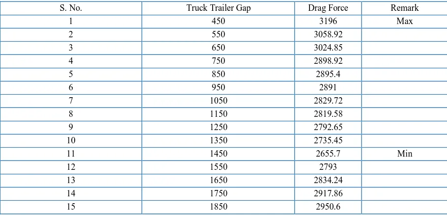
Table 3: Representing analysis results
S. No. Truck Trailer Gap Drag Force Remark
1 450 3196 Max
2 550 3058.92
3 650 3024.85
4 750 2898.92
5 850 2895.4
6 950 2891
7 1050 2829.72
8 1150 2819.58
9 1250 2792.65
10 1350 2735.45
11 1450 2655.7 Min
12 1550 2793
13 1650 2834.24
14 1750 2917.86
[image:5.612.78.533.508.727.2]1167
©IJRASET: All Rights are Reserved
Figure 6: Graph representing the variation of drag force with the increasing gap between truck and trailer
Represents the value of TATA MOTORS
Represents the value of ASHOK LEYLAND
VIII. CONCLUSIONS
A. This project work was to identify the effect of gap between truck & trailer front on the drag force.
B. It has been observed that for a particular gap distance- 1450mm, the drag force exerted on the truck is minimum,with a value of 2655.7 N.
C. Hence, the optimum gap between truck and trailer front has been achieved.
IX.ACKNOWLEDGMENT
We owe our deep gratitude to our project guide, Prof. Mani Kant Paswan, Professor &Head, Mechanical Engineering, who took keen interest on our research work and supervised and guided us all along, till the completion of our research work by providing all the necessary information and encouragement.
REFERENCES
[1] CFD Analysis of Aerodynamic Trailer Devices for Drag Reduction of Heavy Duty Trucks, CHRISTOFFER HÅKANSSON, MALIN J. LENNGREN, master
thesis, Chalmers university.
[2] 2000-01-3500, External Flow Analysis of a Truck for Drag Reduction, Subrata Roy and Pradeep Srinivasan, Kettering University, Flint, MI
[3] CFD analysis for drag force reduction in inter-city buses, Mr. Devesh yadav, Mr. Sumit chauhan, Mr. Shashank karki, Mr. Satya ranjan nayak, Mr. Nitin kumar, Associate Prof. Mr.S.Sudhakar babu.