http://www.scirp.org/journal/ijmpcero ISSN Online: 2168-5444
ISSN Print: 2168-5436
DOI: 10.4236/ijmpcero.2017.64037 Nov. 16, 2017 410 Int. J. Medical Physics, Clinical Engineering and Radiation Oncology
Investigation of Well-Balanced kV X-Ray
Imaging Conditions between Skin Dose and
Image Noise for Dynamic Tumor Tracking
Irradiation
Takahiro Nakai
1, Akira Sawada
2*, Hiroaki Tanabe
3, Masaki Sueoka
3, Sho Taniuchi
3,
Kenji Takayama
4, Takehiro Shiinoki
5, Yoshitomo Ishihara
4, Masaki Kokubo
6,71Department of Radiological Technology, Kobe City Medical Center General Hospital, Kobe, Japan 2Faculty of Medical Science, Kyoto College of Medical Science, Nantan, Japan
3Department of Radiological Technology, Institute of Biomedical Research and Innovation, Kobe, Japan 4Department of Radiation Oncology and Image-Applied Therapy, Kyoto University, Kyoto, Japan 5Department of Radiation Oncology, Yamaguchi University, Ube, Japan
6Division of Radiation Oncology, Institute of Biomedical Research and Innovation, Kobe, Japan 7Department of Radiation Oncology, Kobe City Medical Center General Hospital, Kobe, Japan
Abstract
Purpose: The purposes of this study were to estimate accumulated kV X-ray imaging dose throughout dynamic tumor tracking (DTT) irradiation by Vero 4DRT system and to address an analytical skin dose formula for well-balanced kV X-ray imaging conditions between skin dose and image noise. Method: First, skin dose was measured using kV X-ray tube, chamber, and water-equivalent phan-toms. Next, imaging dose for six patients in DTT treatment was computed us-ing log files. Subsequently, scattered dose ratio was calculated by amount of io-nization in front of flat panel detector (FPD) for fields with size of maximum and the chamber for 0 - 200 mm-thickness phantoms and tube voltage of 60, 80, 100, 120 kV, respectively. Furthermore, image noise was computed from FPD images. Results: The skin dose was greater by a factor of 1.4 - 1.6 than those in Synergy XVI system. The image noise in FPD, N was expressed as
(
)
0.4790.045 1 FPDen ,
N= × Q where QFPDen denotes amount of ionization in front of
FPD. Then, skin dose, D N t v
(
, ,)
was formulated as(
)
(1 0.479)( )
( )
/
0.045N QFPDen mAs t v, ×DmAs v , where QFPDen mAs
( )
t v, and( )
/mAs
D v denote amount of ionization in front of FPD and skin dose per mAs, respectively. Using the formulae, it has been demonstrated that skin dose with 120 kV has become lower than any other tube voltage in this study. Conclusion:
How to cite this paper: Nakai, T., Sawada, A., Tanabe, H., Sueoka, M., Taniuchi, S., Ta-kayama, K., Shiinoki, T., Ishihara, Y. and Ko-kubo, M. (2017) Investigation of Well-Balanced kV X-Ray Imaging Conditions between Skin Dose and Image Noise for Dynamic Tumor Tracking Irradiation. International Journal of Medical Physics, Clinical Engineering and Radiation Oncology, 6, 410-420.
https://doi.org/10.4236/ijmpcero.2017.64037
Received: September 20, 2017 Accepted: November 13, 2017 Published: November 16, 2017
Copyright © 2017 by authors and Scientific Research Publishing Inc. This work is licensed under the Creative Commons Attribution International License (CC BY 4.0).
DOI: 10.4236/ijmpcero.2017.64037 411 Int. J. Medical Physics, Clinical Engineering and Radiation Oncology
Using skin doses for the phantom, the skin dose throughout DTT irradiation was estimated as 0.50 Gy. Furthermore, skin dose by kV X-ray imaging was described as a function of image noise, phantom thickness, and tube voltage, suggesting image noise may be reduced with higher X-ray tube voltage in this phantom study.
Keywords
Dynamic Tumor Tracking Irradiation, Skin Dose, Vero4DRT
1. Introduction
In dynamic tumor tracking (DTT) irradiation using Vero4DRT (Mitsubishi Heavy Industries, Ltd., Japan, and BrainLAB, Germany), four dimensional correlation model (4D model) between positions of 3 - 4 gold markers implanted closely to a tumor and displacement of abdomen is created just before beam delivery. Then, the position of the target is predicted by the 4D model and the displacement of the abdomen measured by the infrared camera system during irradiation [1][2]. 3D positions of gold markers of the diameter of 1.5 mm in the 4D model are calculated by a stereo vision technique using several pairs of 2D positions of each marker in two orthogonal kV X-ray images [3]. Therefore, it is of great importance of quantifying skin dose during acquisition of kV X-ray images.
ICRP publication 85 recommends that skin dose for the heart IVR cases should be recorded and the patient should be followed up when the skin dose is greater than or equal to 3 Gy [4]. AAPM report 75 describes skin dose during acquisition of kV X-ray images using Synergy XVI (Elekta, England) as a reference of kV X-ray skin dose based on the ALARA (as low as reasonably achievable) principle [5].
Image quality of kV X-ray images is greatly dependent on image acquisition condition such as tube voltage and tube current-time product. Then, detectability of gold markers using image processing techniques [6] is varied due to the image quality of kV X-ray images. In addition, detectability of gold markers in lungs is greatly varied due to difference of water-equivalent path in which the gold mark-ers are moving under mediastinum or diaphragm.
The purpose of this study was to estimate the accumulated kV X-ray imaging dose during DTT irradiation by the Vero4DRT using water-equivalent phan-toms [7]. Furthermore, the skin dose was analytically formulated as a function of kV X-ray image noise, tube voltage, and the phantom thickness to investigate well-balanced kV X-ray imaging conditions between skin dose and image noise [8].
2. Materials and Methods
2.1. Measurement of Skin Dose
cy-DOI: 10.4236/ijmpcero.2017.64037 412 Int. J. Medical Physics, Clinical Engineering and Radiation Oncology
lindrical ionization chamber (DC300, IBA Dosimetry, Germany), and water-equivalent phantoms (Tough Water, KYOTO KAGAKU, Japan). Figure 1 represents a pho-tograph of measurement system of exposure dose. The ionization chamber was rigidly attached on the phantom of 200 mm in thickness. Then, the ionization chamber was positioned to 150 mm upper from the isocenter along the beam axis. Subsequently, exposure dose to a fully opened field of 171 × 226 mm2 on
the isocenter plane was measured at a speed of 5 fps with X-ray tube current of 200 mA, and X-ray tube voltage of 60, 80, 100, 120 kV, respectively. The nominal exposure time was set to 5 ms.
Next, half-value layer (HVL) of aluminum was measured using a spherical io-nization chamber (Exradin A4, Standard Imaging Inc., USA) to estimate the effec-tive energy and absorbed dose conversion factor of soft tissue of kV X-ray.
Then, the skin dose was calculated using the following formula:
,
D= ×X F (1)
where D is the skin dose (Gy), X the exposure dose with backscatter (C/kg), and F the absorbed dose conversion factor of soft tissue (Gy∙(C/kg)−1) [10].
2.2. Scattered Dose Ratio in FPD
First, the top surface of the couch was positioned at the isocenter in the vertical direction. Then, the water-equivalent phantoms (Tough Water) of 0, 50, 100, 200 mm in thickness were put on the couch, respectively. Next, the ionization chamber (Exradin A5, Standard Imaging Inc., USA), was rigidly fixed at the midpoint be-tween the FPD and the isocenter, in the air using carton paper. For the irradiation field of 171 × 226 mm2 (fully opened field) and 50 × 50 mm2 which is just
[image:3.595.232.518.526.705.2]involv-ing the ionization chamber, the exposure doses to FPD as the amount of ioniza-tion were measured with X-ray tube voltage of 60, 80, 100, 120 kV, respectively (Figure 2). Then, the ratio of the amount of ionization for the fully opened field subtracted by the amount of ionization for the field involving the ionization chamber to the
DOI: 10.4236/ijmpcero.2017.64037 413 Int. J. Medical Physics, Clinical Engineering and Radiation Oncology
Figure 2. A photograph of measurement system of
scattered dose ratio in FPD.
amount of ionization for the field involving the ionization chamber was computed as the scattered dose ratio in FPD.
2.3. Image Noise in FPD
Under the same condition as described above, amount of ionization in front of FPD was measured with a variety of X-ray tube voltage and thickness of the phantoms of 0, 50, 100, 200 mm for the fully opened field of 171 × 226 mm2.
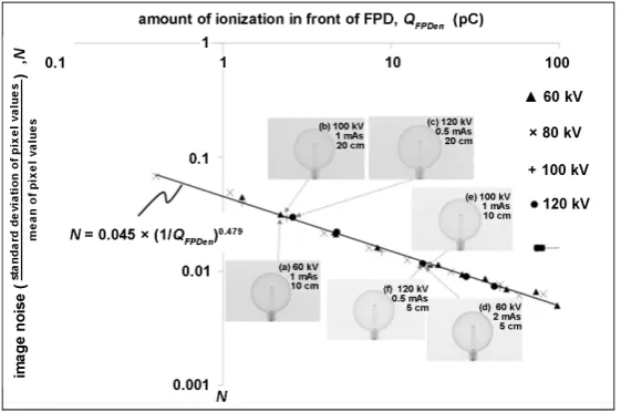
Then, the corresponding FPD images were stored. From the FPD images, the ra-tio of the standard deviara-tion of pixel values within the predetermined region of interest (ROI) with the size of 128 × 128 pixels to the mean within different ROI having little scattered dose from the chamber with the same size was com-puted using Image-J software (National Institutes of Health, USA) as image noise .
3. Results
3.1. Skin Dose
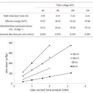
Table 1 represents half-value layer of aluminum, the corresponding effective energy, the absorbed dose conversion factors of soft tissue, and skin doses calcu-lated using Equation (1) for kV X-ray tube voltage of 60, 80, 100, 120 kV, respec-tively.
DOI: 10.4236/ijmpcero.2017.64037 414 Int. J. Medical Physics, Clinical Engineering and Radiation Oncology
Table 1. Skin dose.
Tube voltage (kV)
60 80 100 120
Half-value layer (mm Al) 3.03 4.16 5.26 6.23 Effective energy (keV) 33.57 38.55 43.16 47.04 Absorbed dose conversion factor
(Gy ∙ (C/kg)−1) 35.51 35.43 35.30 35.14
Estimated skin dose per mAs (mGy) 0.034 0.078 0.130 0.205
Figure 3. Skin dose for a single exposure as a function of tube current-time
product.
3.2. Scattered Dose Ratio in FPD
Figure 4 shows variation in the scattered dose ratio in FPD as a function of X-ray tube voltage for the phantoms with 0, 50, 100, 200 mm in thickness, respectively. We have observed that difference in scattered dose ratio in FPD for the phantom with the same thickness was insignificant with respect to the X-ray tube voltage while the scattered dose ratio in FPD became higher for the thicker phantoms. For 60 kV and 80 kV with 200 mm in thickness, the scattered dose ratio could be ignored because of little amount of ionization for the field involving the ioniza-tion chamber. In addiioniza-tion, the above tube voltages were out of the clinical condi-tions.
3.3. Image Noise
Figure 5 shows variations in amount of ionization in front of FPD as a function of the phantom thickness for kV X-ray irradiation of 1 mAs with tube voltage of 60, 80, 100, 120 kV, respectively.
DOI: 10.4236/ijmpcero.2017.64037 415 Int. J. Medical Physics, Clinical Engineering and Radiation Oncology
[image:6.595.235.508.262.446.2]Figure 4. Scattered dose ratio in FPD.
Figure 5. Variations in amount of ionization in front of FPD as a function
of the phantom thickness for kV X-ray irradiation of 1 mAs with tube vol-tage of 60, 80, 100, 120 kV.
Figure 6. Variations of image noise as a function of amount of ionization
[image:6.595.234.515.506.692.2]DOI: 10.4236/ijmpcero.2017.64037 416 Int. J. Medical Physics, Clinical Engineering and Radiation Oncology
From Figure 6, the approximation formula of the image noise in the FPD, N, was expressed as
(
)
0.4790.045 1 FPDen ,
N = × Q (2)
where QFPDen (pC) denotes amount of ionization in front of FPD.
The above approximation formula was not applicable for the patient with thick-ness of 50 mm or less because of greater structure mottle.
4. Discussion
4.1. Comparison of Skin Dose between in the Vero4DRT and in the
Synergy XVI Systems
The kV X-ray source to isocenter distance in the Vero4DRT was very similar to that in the Synergy XVI. The skin dose in the Synergy XVI was 0.08 mGy/mAs for a tube voltage of 100 kV and 0.15 mGy/mAs for a tube voltage of 120 kV, re-spectively [11]. The corresponding skin doses measured in the Vero4DRT were 0.13 and 0.21 mGy/mAs, respectively. The skin doses in the Vero4DRT were greater by a factor of 1.6 and 1.4 than those in the Synergy XVI with the tube voltage of 100 and 120 kV, respectively. It is because the kV X-ray source in the Vero4DRT has no filtration while a 0.1-mm Cu filter is attached to the kV X-ray source in the Synergy XVI [11]. Our previous study [12] has demonstrated that the skin doses in the Vero4DRT with a 0.1-mm Cu filter attached to the kV X-ray source became 1.1 and 0.99 greater than those in Synergy XVI with the tube vol-tage of 100 and 120 kV, respectively. The added filtration to the kV X-ray induces a rise in image noise due to reduction of amount of ionization in front of FPD while reducing skin dose. Therefore, we need to take the amount of image noise as well as skin dose into consideration for determination of an optimal thickness of the added filter.
4.2. Estimation of kV X-Ray Skin Dose in Dynamic Tumor
Tracking Treatment Irradiation for Lung Cancers
Using the Vero4DRT System
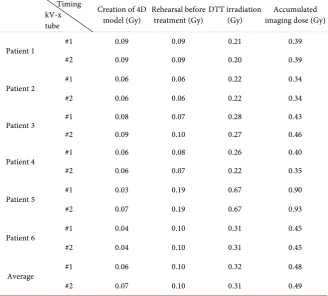
In the protocol of DTT treatment using the Vero4DRT, it is required to create a temporal 4D model between positions of the tumor and those of the abdomen just before the treatment as well as at the rehearsal of the treatment. Then, kV X-ray imaging in two orthogonal directions is performed to acquire the positions of the tumor. Furthermore, another kV X-ray imaging is performed to verify the accuracy of 4D model during the treatment [13].
DOI: 10.4236/ijmpcero.2017.64037 417 Int. J. Medical Physics, Clinical Engineering and Radiation Oncology
Table 2. Estimated imaging dose for dynamic tumor tracking (DTT) irradiation
treat-ment.
Timing kV-x tube
Creation of 4D
model (Gy) Rehearsal before treatment (Gy) DTT irradiation (Gy) imaging dose (Gy) Accumulated
Patient 1 #1 0.09 0.09 0.21 0.39
#2 0.09 0.09 0.20 0.39
Patient 2 #1 0.06 0.06 0.22 0.34
#2 0.06 0.06 0.22 0.34
Patient 3 #1 0.08 0.07 0.28 0.43
#2 0.09 0.10 0.27 0.46
Patient 4 #1 0.06 0.08 0.26 0.40
#2 0.06 0.07 0.22 0.35
Patient 5 #1 0.03 0.19 0.67 0.90
#2 0.07 0.19 0.67 0.93
Patient 6 #1 0.04 0.10 0.31 0.45
#2 0.04 0.10 0.31 0.45
Average #1 0.06 0.10 0.32 0.48
#2 0.07 0.10 0.31 0.49
those should be configured to various angles in clinical situation, leading to de-crease of overlap of the kV X-ray irradiation fields. Therefore, the estimated skin dose throughout the DTT treatment course should be greater than clinical cases. The average accumulated skin dose among kV X-ray tube #1 and #2 was 0.50 Gy while the maximum accumulated skin dose was 0.93 Gy. The above estimated skin doses were less than 3 Gy in case of which the follow-up care is not forced for the heart IVR patients [3], suggesting that DTT irradiation for lung cancers can be performed without special attention about the imaging dose although the summed dose of the skin dose and the treatment dose is required to estimate to-tal dose.
4.3. Scattered Dose Ratio in FPD
Our result has demonstrated that scattered dose to FPD is not increased accord-ing to peak tube voltage; and therefore, the high tube voltage does not decrease image quality.
4.4. Correlation between Image Noise and Skin Dose
From Equation (2), amount of ionization in front of FPD, QFPDen
( )
N (pC) isex-pressed as
( ) (
)
1 0.4790.045 ,
FPDen
DOI: 10.4236/ijmpcero.2017.64037 418 Int. J. Medical Physics, Clinical Engineering and Radiation Oncology
Figure 7. Skin dose computed using Equation (5) for the tube voltage of 60, 80,
100, and 120 (kV), respectively.
Figure 8. Skin dose with the same image noise as with tube voltage of 120 kV.
where N denotes image noise. Then, tube current-exposure time product
(
, ,)
Q N t v is expressed as
(
, ,)
FPDen( )
FPDen mAs( )
, .Q N t v =Q N Q t v (4)
Here, t v Q, , FPDen mAs
( )
t v, denote phantom thickness, tube voltage, amount ofionization in front of FPD per mAs, respectively. Using skin dose per mAs, D/mAs
( )
v , skin dose, D N t v(
, ,)
, is expressed as(
)
(
)
( )
(
)
( )( )
( )
/ 1 0.479 / , , , ,0.045 , .
mAs
FPDen mAs mAs
D N t v Q N t v D v
N Q t v D v
= ×
= × (5)
Next, D/mAs
( )
v was obtained from Figure 3 while QFPDen mAs( )
t v, was obtained0 1 2 3
0 100 200
ski n d o se n or m al iz e d to th e ski n d o se w it h tub e vo lt ag e o f 120 kV
phantom thickness (mm)
60 kV
80 kV
100 kV
[image:9.595.229.518.351.537.2]DOI: 10.4236/ijmpcero.2017.64037 419 Int. J. Medical Physics, Clinical Engineering and Radiation Oncology
from Figure 5. Using Equation (5), skin dose was computed for the tube voltage of 60, 80, 100, 120 (kV), respectively, as shown in Figure 7.
Figure 8 depicts variations in skin dose with the same amount of image noise as a function of phantom thickness for each tube voltage. Each skin dose was normalized to the skin dose with tube voltage of 120 kV. From Figure 8, the skin dose with tube voltage of 120 kV has analytically become lower than that with any other tube voltage in this phantom study, although skin dose during image guided radiation therapy may be taken into account because of lots of imaging number.
5. Conclusion
We have measured skin dose induced by kV X-ray imaging for image guidance using water-equivalent phantoms and the Vero4DRT system. The measured skin dose was comparable with the skin dose using the Synergy XVI system under the similar kV X-ray imaging conditions. Using skin doses for the above phantom, the accumulated skin dose throughout the dynamic tumor tracking irradiation treat-ment course for lung cancers was estimated as 0.50 Gy. Furthermore, the skin dose in kV X-ray imaging in the Vero4DRT system was described as a function of the image noise, the thickness of the phantom, and the X-ray tube voltage, suggest-ing that the image noise will be reduced with higher X-ray tube voltage.
Conflict of Interest
Research sponsored in part by Mitsubishi Heavy Industries, Ltd.
References
[1] Mukumoto, N., Nakamura, M., Sawada, A., Takahashi, K., Mizowaki, T., Kokubo, M. and Hiraoka, M. (2011) Geometric Accuracy of the X-Ray Image-Based Dynam-ic Tracking for a Four-Dimensional Image-Guided Radiotherapy System with Gimbals Mechanism of MHI-TM2000 (Vero). 2011 Joint AAPM/COMP Meeting, Vancouver, 31 July-4 August 2011, 3477. https://doi.org/10.1118/1.3611919
[2] Mukumoto, N., Nakamura, M., Sawada, A., Takahashi, K., Miyabe, Y., Takayama, K., et al. (2010) Verification of the Tracking Accuracy for a Four-Dimensional Im-age-Guided Radiotherapy System with a Gimbaled X-Ray Head, MHI-TM2000.
Proceedings of 10thAsia-Oceania Congress of Medial Physics, Taipei, 15-17 October
2010, 88.
[3] Depuydt, T., Poels, K., Van Gompel, G., Buls, N., Gevaert, T., Duchateau, M., et al.
(2011) Low Dose Based Detection of Implanted Marker Position on the VERO Sys-tem for Real-Time Tumor Tracking. 2011 Joint AAPM/COMP Meeting, Vancouver, 31 July-4 August 2011, 3605.
[4] Cardella, J., Faulkner, K., Hoperwell, J., Nakamura, H., Rehani, M., Rosenstein, M., et al. (2000) Avoidance of Radiation Injuries from Medical Interventional Procedures. ICRP Publication 85, Annals of the ICRP. SAGE Publications Ltd., Thousand Oaks, 30. [5] Murphy, M.J., Balter, J., Balter, S., BenComo, J.A., Das, I.J., Jiang, S.B., et al. (2007)
The Management of Imaging Dose during Image-Guided Radiotherapy: Report of AAPM Task Group 75. Medical Physics, 34, 4041-4063.
DOI: 10.4236/ijmpcero.2017.64037 420 Int. J. Medical Physics, Clinical Engineering and Radiation Oncology
[6] Siedband, M., Baiter, B., Morgan, T., Bratemann, L., Properzio, W., Britt, W., et al. (1977) Basic Quality Control in Diagnostic Radiology. AAPM Report No. 4. https://aapm.org/pubs/reports/rpt_04.pdf
[7] Balter, S., Fletcher, D.W., Kuan, H.M., Miller, D., Richter, D., Seissl, H., et al. (2002) Techniques to Estimate Radiation Dose to Skin during Fluoroscopically Guided Procedures. Skin Dose Measurements AAPM, July 2002.
http://citeseerx.ist.psu.edu/viewdoc/download?doi=10.1.1.483.6023&rep=rep1&type =pdf
[8] Steven, W.S. (1997) The Scientist and Engineer’s Guide to Digital Signal Processing. California Technical Publishing, San Diego.
[9] Kamino, Y., Miura, S., Kokubo, M., Yamashita, I., Hirai, E., Hiraoka, M. and Ishi-kawa, J. (2007) Development of an Ultrasmall C-Band Linear Accelerator Guide for a Four-Dimensional Image-Guided Radiotherapy System with a Gimbaled X-Ray Head. Medical Physics, 34, 1797-1808. https://doi.org/10.1118/1.2723878
[10] Selzer, S.M. and Hubbell, J.H. (1995) Table and Graphs of Photon Mass Attenuation Coefficients and Mass Energy-Absorption Coefficients for Photon Energies 1 keV to 20MeV for Elements Z = 1 to 92 and Some Dosimetric Materials. JSRT Japanese So-ciety of Radiological Technology Press, Kyoto.
[11] Islam, M.K., Purdie, T.G., Norrlinger, B.D., Alasti, H., Moseley, D.J., Sharpe, M.B.,
et al. (2006) Patient Dose from Kilovoltage Cone Beam Computed Tomography Im-aging in Radiation Therapy. Medical Physics, 33, 1573-1582.
https://doi.org/10.1118/1.2198169
[12] Nakai, T., Itou, T., Kubo, K., Sueoka, M., Tanabe, H., Furukawa, H. and Kokubo, M. (2011) Measurement of Imaging Dose toward Pursuit Irradiation; A Preliminary Study. 67th Japanese Society of Radiological Technology, Yokohama, 7-10 April 2011, 257. [13] Hirai, E., Tsukuda, K., Kamino, Y., Miura, S., Takayama, K. and Aoi, T. (2009) MHI’s