OWNER'S MANUAL
Model 2422
-B
Floppy Disk (;ontroller
= = = = ' = = = = = = = = = = = : = = =
MULTIMODE FLOPPY DISK CONTROLLER
REFERENCE MANUAL
89000-02422 Rev B
Copyright 1981
All rights reserved. No part of this publication may be reproduced in any form or by any means without express permission of California Computer Systems.
The information contained in this manual is believed to
be correct at the time of publication. However, CCS
assumes no liability resulting from the use of this manual.
Z-80 is a registered trademark of Zilog, Inc.
CP/M is a registered trademark of Digital Research, Inc.
Publication History:
1 . ~I INTRODUCTION
1.1 General Description . . . 1-1 1.2 The 2422 and System Compatibility . . . 1-2 1.3 Drive Compatibility . . . 1-4 1.4 Diskette Compatibility . . . 1-5 1.5 Specifications . . . 1-7
2.0 USER OPTIONS
2.1 Auto Boot O,ption . . . 2-1 2.2 PerSci Drive Options . . . 2-2 2.3 Options for System/Software Compatibility . . . 2-5
3.~' INSTALLATION AND OPERATION
3.1 3.2 3.3 3.4
System Configuration . . . . Drive Configuration . . . .
Installation . . . .
Operation
4." THE 2422 ROM:-RESIDENT FIRMWARE
3-1 3-2 3-7 3-8
4.1 Cold-start Entry . . . 4-1 4.2 Page 0 RAM Used by Firmware . . . 4-2 4.3 The Firmware Disk Routines . . . 4-2 4.4 The Monitor's I/O Routines . . . 4-4 4.5 The Bootstrap Loader . . . 4-8
4.6 The Monitor' . . . • . . . 4-9
5 .,~ THEORY OF OPERA'rION
5.1 5.2 5.3
The 2422 Registers
The Sys tern Inter face . . . . The Disk Drive Interface . . . ~ . . . .
A.0 PROGRAMMING INFORMATION
A.1 The 2422 Accessible Registers . . . A-I A. 2 Diskette Forma"t . . . A-2
B.0 THE 1793 DATA SHEET
C.o FIRMWARE LISTING
D.0 TECHNICAL INFORMATION
D.1 System Bus Interface . . . 8 • • • • • • • • D-1
D.2 Drive Bus Interface . . . ~ . . . D-3 D.3 User Replaceable Parts . . . D-5 D.4 Assembly Drawing . . . D-7
D.5 Schematic . . . D-9
TABLES AND FIGURES
Table 1-1 Plug-compatible Drives . . . 1-1
Table 1-2 Firmware-compatible Diskette Formats . . . 1-2
Table 4-1 Low RAM Locations Used by Firmware . . . 4-2
Table 4-2 Disk Parameters . . . 4-4
Table 4-3 Physical-to-Logical Device Assignments . . . 4-3
Table 4-4 The Basic I/O Routines . . . 4-6 Table 4-5 Disk Parameters after Boot . . . 4-9 Table 4-6 Assign Command Codes . . . 4-13 Table 4-7 Sectors per Track . . . 4-18 Table 5-1 U16b Outputs . . . 5-7
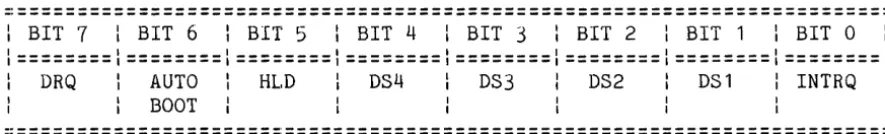
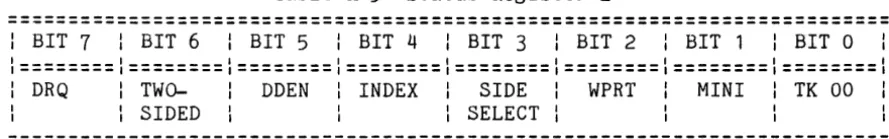
Table A-I 2422 Register Addressing . . . A-I Table A-2 Control Register 1 . . . A-2 Table A-3 Status Register 1 . . . A-3 Table A-4 Control Register 2 . . . A-4 Table A-5 Status Register 2 " . . . A-5 Table A-6 Bank Select Register . . . A-5
Table A-7 Single-density Diskette Format . . . A-7
Table A-8 Double-density Diskette Format . . . A-8
Table D-1 System Bus Signals . . . D-1 Table D-2 Drive Bus Signals . . . D-3
Figure 2-1 Jumper Locations . . . 2-2
Figure 2-2 Jumper Configuration for PerSci Drives . . . 2-3
INTRODUCTION
1.1 A GENERAL DESCRIPTION ON THE 2422
CCS's 2422 Floppy Disk Controller supports single- and
double-density data formats, single- and double-sided 5.25"
and 8" drives, and provides 2K ROM containing software
debugging routines and a bootstrap loader for loading CP/M
(Digital Research's single-user operating system) from
diskette. The 2422 is designed especially for use in CCS's
system 2210, but provides a number of user options for
compatibility with other systems and software.
The 2422 incorportates the following features:
*
Ability to control up to four drives in any combination ofsingle-sided or double-sided 5.25" and 8" drives.
*
Compatibility with the IBM 3740 and System 34 standards forsingle- and double-density diskette formats.
*
ROM-resident monitor program and bootstrap loader.*
Auto Boot option allowing CP/M to be booted in on reset.*
Compatibility with either Shugart or per8ci drive buses*
Compatibilty with IEEE proposed 8-100 bus*
A compatible version of CP/M that supports single- anddouble-density diskette formats in 128, 256, 512, and 1024
1.1.1 ROM-resident Firmware Overview
The ROM-resident firmware consists of the bootstrap
loader and CCS's monitor, the MOSS 2.2 Disk Monitor. The
bootstrap loader is designed to read into memory the system
loader on the first sector of the system diskette and transfer
control to it. The system loader in turn reads in the
operating system and disables the monitor ROM, freeing its 2K
of memory space. The MOSS 2.2 Disk Monitor provides routines
for basic console control and software debugging and is
designed to work with CCS's 2810 Z-80 CPU. Both the bootstrap
loader and the monitor are described more thoroughly in
Chapter 4, "The ROM-resident Firmware."
1.1.2 CCS's Implementation of CP/M
The 2422 is shipped with a compatible version of CP/M.
CP/M is organized so that the device-dependent I/O drivers and
disk routines are located in the portion of the operating
system known as the BIOS (Basic I/O System) • The version of
CP/M on the diskette shipped with the 2422 contains a modified BIOS, called CCBIOS, which is designed to work with the System
2210. The basic principles and operation of CP/M are
described in Digital Research's manual "An Introduction to
CP/M Features and Facilities," while CCS's modifications and
additions to CP/M are described in CCS's manual "CCS's
Controller-unique Software." Both are in your CP/M binder.
1.2 THE 2422 AND SYSTEM COMPATIBILITY
1.2.1 General
The 2422 is compatible with systems conforming to the
IEEE proposed standards for the S-100 bus.
Note that the 2422 does not contain a serial I/O port.
In CCS's System 2210, the serial port for the console is
located on the CPu. If you do not own a 2810 Z-80 CPU, the
1.2.2 Firmware Requirements
The basic system requirements for firmware compatibility
are listed below. Since the monitor firmware is designed to
work with CCS's 2810 CPU, systems with a 2810 CPU configured
as described in Section 3.1 meet reqriirements 2, 3, and 4
bE!low.
1. Both the Monitor and bootstrap loader require that roughly
256 bytes of low RAM (0000h-00FFh) be available on system
reset In addition, memory sharing the ROM's address space
(F000h-F7FFh) should be capable of being disabled or
overlaid when the ROM is being accessed. See Section 3.1
for information on configuring your system memory.
2:. The ROM-resident firmware requires a Z-80 CPU, since the
firmware uses the Z-80 instruction set. The Z-80's
instruction set contains 80 more instructions than the
8080's. Most of the Z-80 special instructions are
condensations of several 8080 instructions into one
instruction; owners of an 8080 CPU could thus expand the
Z-80 instructions into their 8080 equivalents should they
wish to use the ROM firmware. However, some monitor
routines will have to be pared down or eliminated, since
an 8080 version of the firmware will require more space.
Modifying the firmware involves programming a
user-supplied 2716-type ROM with the revised software and
replacing the original ROM with the newly-programmed ROM.
3. In order for the ROM firmware to be accessed automatically
on power-on or reset, you must have a power-on jump
circuit somewhere in your system set to force the CPU to
address F000h on system reset.
4. The console I/O routines in the Monitor firmware are
designed to drive the 2810 CPU's serial port. If you do
not have a 2810 CPU and wish to use the Monitor, you will
have to modify the console driver routines. Section 4.4.3
contains instructions on how to do so. The bootstrap
loader does not use the console I/O routines; thus if you
use the 2422 in the AUTO BOOT mode (Section 2.1) in which
only the bootstrap loader is accessed, the ROM firmware
1.2.3 Operating System Requirements
Your system must meet the following requirements to be
compatible with CCS's controller-unique version of CP/M.
1. CP/M requires 20K of continuous RAM, starting at 0000H.
CCS's distribution version is configured for 20K systems,
but can be reconfigured for systems with larger memory:
see MOVCPM in the Controller-Unique Software manual.
2. The system loader, CCBOOT, contains Z-80 unique
instructions and thus requires a Z-80 CPU. Owners of an
8080 CPU must translate the Z-80 instructions into 8080
instructions. CCBOOT also requires a 4 MHz system clock
to read double-density system diskettes. CCS's customized
BIOS, CCBIOS, is both 8080 and Z-80 compatible.
3. Like the firmware console driver routines, the console
driver routines in CCBIOS drive the 2810 CPU's serial
port. If you are using a different CPU, you must alter
the console I/O routines as described in Application Note
1 of the CCS Controller-Unique Software manual.
1.3 DRIVE COMPATIBILITY
1.3.1 General
The 2422 is designed to control soft-sectored floppy disk
drives and to be plug-compatible with Shugart-type or perSci
drives. As shipped, the 2422 is configured for Shugart-type
drives. The following table lists some of the drives which
are compatible with Shugart drives:
===========================================================
811 5.2511
=========================================================== Shugart SA800 or 850
Memorex 550 or 552 Qume DataTrak 8
Seimans FDD 100-8 or 200-8 Remex 2000 or 4000
Shugart SA400 or SA450 MPI 51 or 52
MPI 91 or 92 Tandon TM 100
===========================================================
Owners of perSci drives will have to make the cut-and-jumps described in Sections 2.2.1 through 2.2.6 before the 2422 is plug-compatible with their drives.
All drives contain user options, some of which support daisy-chaining two more drives together. See Section 3.2 on configuring drives.
1.3.2 Firmware/Operating System Requirements
The bootstrap loader/monitor firmware should work with most of the drives listed above, since the basib disk parameters for any read or write operation (track number, single or double-sided drive, etc.) must be specified by the user before each operation. A few drive models, however, may need a faster step rate than specified in the firmware, thus requiring a modification of the firmware (firmware step rates are 30ms for 5.25" drives and l0ms for 8" drives). Refer to Section 4.4.3 for instructions on altering the step rates.
The basic disk parameters in CCS's BIOS are fixed, limiting the type of drives that can be used with the operating system. The basic disk routines in CCS's BIOS are designed for Shugart-type single- or double-sided 8" drives with 77 tracks per side and Shugart-type single-sided 5.25" drives with 35 tracks per diskette. The number of tracks per side for the 8" drives is currently an industry standard; however, the number of tracks on 5.25" drives may vary. Should you own a drive with a different number of tracks, or wish to implement double-sided 5.25" drives, see the Application Notes in the Controller-unique Software manual.
In addition, the CCS firmware/software also requires that certain drive options be enabled/disabled. Section 3.2 contains general instructions on drive configuration, as well as specific examples.
1.4 DISKETTE COMPATIBILITY
1.4.1 General
2) contain 128, 256, 512, or 1024 bytes per sector. Although
the IBM standards were designed for 8" diskettes only, the
1793 will read 5.25" diskettes whose formats are adapted from
the standards. Some minor variations from these standards are
allowed; if you will be writing your own software for the
2422, review the format specifications in the 1793 data sheet
in Appendix B. please note that the 1793 cannot read
diskettes formatted by the 1771 disk controller chip, although the 1771 can read diskettes formatted by the 1793a
1.4.2 Firmware/Operating System Requirements
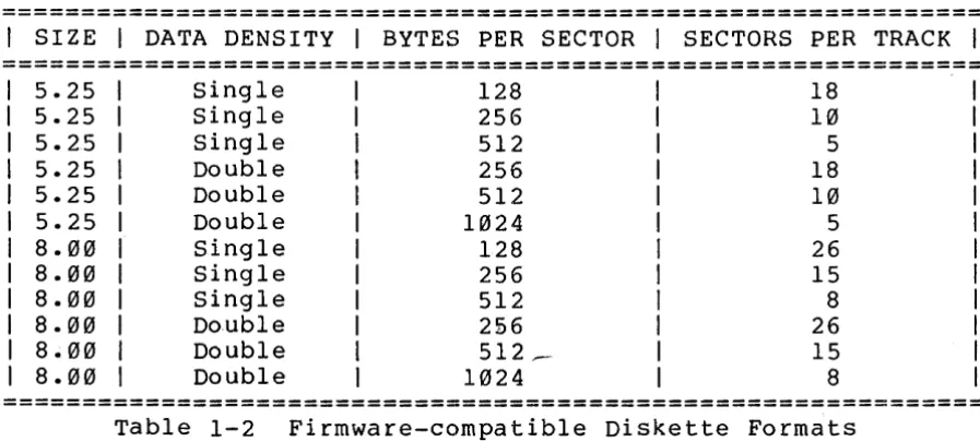
The following table shows the diskette formats supported
by the ROM-resident firmware:
==============================================================
I
SIZEI
DATA DENSITYI
BYTES PER SECTORI
SECTORS PER TRACKI
==============================================================
5.25 Single 128 18
5.25 Single 256 10
5.25 Single 512 5
5.25 Double 256 18
5.25 Double 512 10
5.25 Double 1024 5
8.00 Single 128 26
8.00 Single 256 15
8.00 Single 512 8
8.00 Double 2£6 26
8.00 Double 512 __ - IS
8.00 Double 1024 8
==============================================================
Table 1-2 Firmware-compatible Diskette Formats
CCS's version of CP/M additionally supports single-density
diskettes formatted in 1024-byte sectors and double-density
diskettes formatted in 128-byte sectors. (Refer to Table 2-1
in the manual "CCS's Controller-unique Software.") The first
track (Track 00) of any diskette MUST be formatted in
128-byte, single-density sectors. CCS's utility program
CCSINIT automatically formats the first track of any diskette
in 128-byte single-density sectors. Note that CCSINIT
supports only those formats shown in Table 1-2 above; it does
not support the additional formats supported by the operating
[image:11.615.79.528.311.513.2]1.5 SPECIFICATIONS
DRIVE INTERFACE CHARACTERISTICS
Type Drives:
Number of Drives:
Drive Bus:
Compatible Disks:
Single- or double-sided 5.25" drives Single- or double-sided 8" drives
Four maximum of any type or combination
8"--Shugart SA850-type
Reconfigurable for per Sci 277/299 5.25"--Shugart SA450 type
Single-density, IBM 3740 format
Double-density, IBM System 34 format 128, 256, 512, 1024 bytes per sector
SYSTEM INTERFACE CHARACTERISTICS
System Bus
Firmware
S-100, compatible with proposed standards IEEE Task 696.1
MOSS 2.2 Disk Monitor/Bootstrap Loader
PHYSICAL SPECIFICATIONS
Disk Controller
Memory
Power Requirements
Dissipation
Environmental
Western Digital's FDl793
2316-type 2K ROM
Replaceable with a user-programmed 2716
+8 volts @ .800 amps
+16 volts @ .050 amps
less than 8 watts
o
to 70 degrees CelsiusUSER OPTIONS
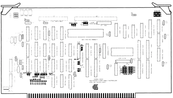
The 2422 is shipped from the factory configured for use in a System 2210 with Shugart-type drives. Those users whose system fits this description need only be concerned with the AUTO BOOT option; once they have configured this option, they may turn to Chapter 3. Owners of a System 2210 with perSci drives will want to read Sections 2.2.1 through 2.2.6 as well.
Sections 2.3.1 through 2.3.7 describe user options designed for compatibility with other systems and software. Figure 2-1 on the following page shows the location of each jumper option and the configuration of the option as shipped from the factory.
2.1 AUTO BOOT OPTION
R6
._... .~.-.-. -... '.:-~ ... -.. o::m
Figure 2-1 Jumper Locations
c::
CIl
tx:l
:::0
o
I"CJ
t-3 H
o
Z
[image:14.797.114.697.132.464.2]If the shorting plug is removed, the monitor will be
entered on power-on and reset. CP/M can then be loaded in
under monitor control by use of the Boot command. Entering
the monitor on reset allows the user to take advantage of the
monitor's console port initialization routines which
initialize the 2810 serial port's baud rate to the baud rate
set by the console device. The console device's baud rate can
be set to any baud rate between 2 and 56K baud. The shorting
plug can be stored on the board by placing one end on either
pin 1 or pin 2 and letting the other end swing free.
2.2 PERSCI DRIVE OPTIONS
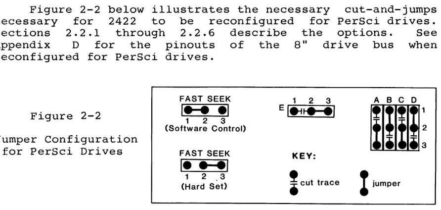
Figure 2-2 below illustrates the necessary cut-and-jumps
necessary for 2422 to be reconfigured for PerSci drives.
Sections 2.2.1 through 2.2.6 describe the options. See
Appendix D for the pinouts of the 8" drive bus when
reconfigured for PerSci drives.
FAST SEEK 1 2 3 ABC 0
Figure 2-2
I .... .1
1 2 3 EI4ti~III
(Software Control>
XiIi:
Jumper Configuration
for PerSci Drives FAST SEEK KEY:
1
... 1
!
cut tracet
jumper1 2 3
(Hard Set)
2.2.1 Fast Seek
The FAST SEEK option is provided for users with voice
coil drives. It allows the user to choose between
software-or hardware-enabling of the fast seek mode. Soldering a wire
connecting pads 1 and 2 allows you to enable the fast seek
mode by writing a 0 to bit 4 of Control Register 2. Soldering
a wire connecting pads 2 and 3 permanently enables the fast
seek mode. If you are planning to use the ROM-resident
fi.rmware or the CCS version of CP/M, the fast seek mode will
be! enabled only if you set the jumper pads 2 and 3, since the
[image:15.612.90.536.298.510.2]2.2.2 Drive Select 3
PerSci drives use pin 18, the Shugart drives' HEAD LOAD
line, for DS3 (Drive Select 3). To enable DS3, cut the trace
between Al and A2 and solder a wire between pads A2 and A3.
2.2.3 Drive Select 4
Shugart drives have DS4 (Drive Select 4) on pin 32 of the
bus: PerSci drives have i t on pin 4. To enable DS4 on pin 4,
cut the wire between pads B2 and B3 and solder a wire between
pads BI and B2.
2.2.4 Side Select
The Shugart double-sided drive uses pin 2 of the bus for
TG43 (Track greater than 43): the PerSci double-sided drives
use i t for SIDE SELECT. To enable the SIDE SELECT line for a
PerSci double-side drive, cut the trace between pads Cl and C2
and solder a wire between traces C2 and C3. This modification
allows the CCS software to support double-sided PerSci drives.
2.2.5 Remote Eject
The Shugart 8" double-sided drive bus uses pin 14 for the
output SIDE SELECT, while PerSci drives use i t for REMOTE
EJECT. To enable REMOTE EJECT for a PerSci drive, cut the
trace between pads 02 and 03 and solder a wire between 01 and
02. Once this feature has been installed, writing a 1 to port
04H will eject the diskette in the selected drive. CCS
software does not support the PerSci remote eject feature.
2.2.6 Seek Complete
Pin 10 of the drive bus is used for the status signal
TWO-SIDED by the Shugart double-sided drive and for the status
signal SEEK COMPLETE by PerSci drives. To enable SEEK
COMPLETE, cut the trace between pads El and E2 and solder a
2.3 OPTIONS FOR SYSTEM/SOFTWARE COMPATIBILITY
2.3.1 Bank Byte Option
Like CCS's RAM cards, the 2422 Disk Controller can be hardware assigned to one of eight banks, or levels, of 64K, allowing up to eight disk controllers can be used in one system. To assign the 2422 to a bank, solder a horizontal jwnper between the BANK BYTE pins which correspond to the bank level to which you want this board assigned. For example, jumpering pads D0 assigns this board to bank 0. Once you have assigned this board to a bank, you can in turn select that bank and enable the board by outputting to port 40 a data byte with a logic 1 in the bit position corresponding to the bank level. For example, the following Z-80 code fragment would activate bank 3 and deactivate all other banks:
LD A,000001000B OUT 40H,A
;load accumulator with bank control byte ;output bank control byte to port 40H
Although the primary purpose of multiple banks is to support multi-users, CCS's single-user system 2210 uses the Bank Select system to simultaneously disable the monitor ROM and enable high RAM (see Section 3.1). To support this function, the BANK BYTE pads should be left open entirely.
2.3.2 Bank Enable option
2.3.3 ROM Enable Option
The ROM Enable option allows you to choose between two
methods of enabling/disabling the bootstrap loader and monitor
firmware. If you leave pads land 2 of the ROM ENABLE jumper
shorted, the bootstrap loader and monitor are enabled cwhen
your system is turned on or reset and disabled when any data
byte is output to port 40h. (Because port 40h is the Bank
Select Port as well, you must make sure that the 2422 is
either permanently bank-enabled or bank-enabled on reset.)
This method of disabling the ROM is used by CCS's CP/M loader,
CCBOOT. When i t is loaded into memory by the boot-strap
loader, CCBOOT outputs a 0lH to port 40H. This will
simultaneously disable the ROM while enabling any RAM assigned to bank 0.
If you cut the trace between pads land 2 and solder a
wire between pads 2 and 3, the ROM can then be
enabled/disabled entirely through software control. Writing a
o
to bit 1 of Control Register 2 enables it: a 1 disables it.2.3.4 Partial ROM Option
This option allows the portion of the ROM containing the
basic I/O and primitive disk routines used by the monitor to
be available after CP/M is loaded in. This portion of the
ROM, located at F600h-F7FFh, contains essentially the same
basic I/O routines as CCS's customized BIOS, CCBIOS, on the
distribution diskette. If you are planning to tailor the
CCBIOS to your system, you may wish to have your customized
BIOS call some of the routines located in the ROM. This will
give you the greater reliability of ROM memory and save some
disk space. To allow the basic I/O portion of the ROM to
remain in memory after CP/M is loaded in, solder a wire
between pads 1 and 2 of the PR EN jumper.
You must leave the basic I/O portion of the ROM disabled
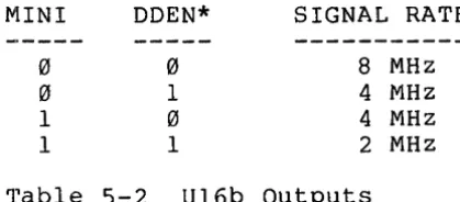
2.3.5 ROM Wait State option
The on-board ROM has the relatively slow memory access
time of 450 nsecs. A CPU running at 4 MHz will not provide
the access time needed by the ROM. The 1793 registers, when
they are memory mapped, also have slow memory access times.
If pads 1 and 2 of the WAIT jumper are left open
(factory-configuration), the ROM Wait circuitry is enabled,
inserting one Wait state per memory cycle in which either the
ROM or the 1793 is selected. If a wire is soldered between
pads 1 and 2, the ROM Wait circuitry is disabled.
2.3.6 Memory Map Option
CCS makes available to its 2422 users a control ROM which
allows the registers on the 2422 to be memory mapped when the
ROM is inserted into the socket for U21. The registers then
occupy memory addresses FFF8H-FFFDH. See Appendix A for a
more detailed description of the 2422 register addressing. If
you plan to use the memory map option, you can enable memory
mapping by installing a wire between pads 1 and 2 of the M MAP
jumper. The CCS firmware/software does not make use of memory
mapping.
2.3.7 Interrupt Options
The interrupt jumpers allow you to tie DRQ and/or INTRQ
to either the Interrupt line (INT) , the Nonmaskable Interrupt
line (NMI) , or any of the 8 vectored Interrupt lines
(VI0-VI7). INTRQ, when active, indicates that a command has
been completed and that the 1793 is awaiting a new command.
DRQ, when active, indicates that the data buffer either has a
byte to be read or requires a new byte to transmit, depending
on the nature of the disk operation in progress. Either or
both of these lines can be used to generate interrupts and
thus request servicing from the processor. To generate VI2 by
the active INTRQ, for example, run a bus wire from the INTRQ
pad to the VI2 pad and solder i t in. CCS firmware/software
INSTALLATION AND OPERATION
3.1 SYSTEM CONFIGURATION
In order for the ROM-resident firmware to work as
described in Chapter 4 or for CP/M to be loaded properly, you
must set up your system as follows:
1. Set your system's power-on jump circuit to force the CPU
to jump to location F000h when you turn your system on or
reset it. If you own a 2810 Z-80 CPU, you must set the
JMP EN jumper t~o ON and set the JUMP ADDRESS SEL jumpers
JA0-JA11 to 0 and JA12-JA15 to 1.
2. Ensure that any RAM sharing the ROM's memory space cannot
be accessed while the firmware is being accessed. You
may use the 2422's PHANTOM output to do so if your RAM
responds to the signal. Or, if your RAM uses the same
bank select system as the 2422, you can configure your RAM
such that the memory block sharing the ROM's memory space
is bank-disabled on power-on or reset. By assigning the
block to bank 0, you can ensure i t will be enabled at the
same time the system loader, CCBOOT, disables the ROM by
outputting 01B to port 40H. On the 2065 this method of
enabling/disabling the RAM can be accomplished by setting
the BLOCK SEL jumper for Block 4 to BE, the BANK PORT
ADDRESS jumpers A7-A0 to 01000000, and selecting D0 of the BANK BYTE SEL :jumpers.
Note that if you wish to keep the basic I/O portion of the
ROM enabled after CP/M is loaded, you have to use the
PHANTOM outpuit to disable the RAM sharing its memory
3. Ensure that at least 256 bytes of low RAM are enabled on reset: since CP/M requires at least 20K of continuous RAM,
i t would be wise to enable all RAM except that which
directly conflicts the ROM. On the 2065 this would
involve setting the BLOCK SEL jumpers for Blocks 1, 2, and 3 to ME (the bank-independent position).
If you own a 2810 Z-80 CPU, you must also do the following:
1. Set the SERIAL ADDRESS SELECT jumpers to 20H and the SER
EN jumper to ON.
2. Disable the CPU's monitor ROM (ROM EN=OFF) when you are
running CP/M in a 60K or greater system.
3.2 DRIVE CONFIGURATION
All drives come with customer-configurable options,
usually realized in the form of Berg jumpers or programmable
shunts on the PC board. If you are planning to use only one
mini drive, i t can usually remain as configured by the
factory. If you are using an 8" drive or more than one of the
same size drive, you'll need to reconfigure your drives. The
following two sections give general rules regarding the
configuration of 8" and mini drives and give explicit
configuration instructions for a few models of each size
drive. Some of the models have gone through several revisions
since they were first introduced: as result the setup
instructions will not always be the same for two drives of the
same model. If you have questions, contact your drive
manufacturer.
3.2.1 8" Drive Configuration
The following general rules apply to all 8" drives:
1. The 2422 firmware/software requires that a drive be able
to perform seeks without its head loaded. To enable a
drive to do so, you must make its stepper circuitry
dependent on DRIVE SELECT and independent of HEAD LOAD.
In some cases DRIVE SELECT is terminated with HEAD LOAD;
since this option separates DRIVE SELECT from the HEAD
LOAD termination, DRIVE SELECT will need to be separately
2. Some drives can be configured for either hard-sectored and
soft-sectored diskettes. Select soft-sectored.
3. Two-sided drives should be optioned out so that the disk
side is selected by the SIDE SELECT signal. This is the
standard drive configuration. In addition, the 2422
software requires the TWO-SIDED status signal be enabled.
If you are daisy-chaining two or more drives:
4. You must make sure that the common active lines are
terminated in the last drive on the cable only. This may
involve shorting traces, or removing jumper plugs or
resistor packs: see your drive manual.
5. You must also enable the appropriate Drive Select line to
each drive, usually accomplished by moving a jumper plug.
These are four Drive Select lines available, allowing each
of four drives to be independently selected. Many drives
also allow the option of chaining up to eight drives
together; the 2422 does not support this option.
6. To avoid electrical noise and improve disk access speed,
we recommend you make the Head Load signal independent of
the Drive Select signal, if your drive gives you the
option. This will cause all the drives to load at the
same time and stay loaded for the duration of a read/write
operation. Since all heads load, you also want to make
the Activity LED on the drivels front panel independent of HEAD LOAD and dependent on DRIVE SELECT only.
Most drives offer additional options to the ones mentioned
above. These should be left in the factory configuration.
3.2.2 Examples of 8" Drive Configuration
Below are specific instructions on configuring selected
drives so that they conform to rules 1 through 6 above.
SHUGART SA800
1. Plug traces DS and C. Remove plug from Band HL.
Terminate DRIVE' SELECT by plugging T2.
2. Close,800; open 801.
For daisy-chaining more two or more drives:
4. PI ug Tl, T3,
interface only. on the bus.
T4, T5, T6 in the last drive on the bus
Leave these pins open on all other drives
5. Plug one of the following Orive Select pins: OSl, OS2,
OS3, or OS4. Pads DOS, 01, 02, and 04 should be left
unnconnected.
6. Close A, X, and
z.
Open Y.SHUGART SA850/85l, REMEX RF02000/200l, REMEX RF04000/400l,
MEMOREX 550/552, QUME OATATRAK 8
1.
2.
3.
Cut traces Band HL on the drive's programmable shunt.
Leave the traces Z, A, X, I, and R on the shunt shorted.
pI ug OS and C.
Plug~~ollowing traces in the following drives: 850
(Shugart) ;--q000 (Remex 4000); 2000 (Remex 2000); SSE
(Memorex). Leave ope""n; 851 (Shugart); 4001 (Remex 4000);
2001 (Remex 2001); HSE and HSI (Memorex). Cut S- on the
Shugart and Remex programmable shunts. The Qume drive
does not have a hard sector option.
In the double-sided drives, short 2S and S2 to enable the
signals TWO-SIOEO and SlOE SELECT. Leave open Sl, S3, 18,
28, 38, and 48 (or alternatively, Bl-84).
For more than one drive:
4. Remove the terminating resistor pack in all drives except
the drive that is electrically last on the cable. (At
location 3H in our Shugart, 7A in our Remex, and 2F in our
Memorex.) The Qume has two resistor packs that need to be
removed: ITM and 2TM.
5. Jumper only one of the following: OSl, OS2, OS3, or OS4
(located by Jl). Leave 00 in the Shugart and Memorex
plugged. On drives that allow up to eight drives in a
daisy chain, pins OOS, 01, 02, and 04 should be left
unconnected.
6. Open Y.
SIEMENS FOO 100-8 and 200-8
1. Remove the vertical jumper between G pads and place a
2. Leave SS shorted and HS open. (Both jumpers are located by 2C.)
3. For the 200-8, make sure that a jumper exists between the
horizontal 7 pads and that the vertical 8 pads are open.
The Side Sel pads 3-0 should remain open.
F~r daisy-chaining two or more drives:
4. Remove terminating resistor on all drives but the last on
the bus interface.
5. plug one of the following RAD SEL (Radial Select) pins: 0,
1, 2, 3. These pins correspond to the DSl, DS2, DS3, DS4
on other drives. Leave the Binary Select pins 0-7 open.
6. Remove the wire jumper between the vestical L pads and
install a wire on the horizontal J pads. For the activity
LED to light on Drive Select, leave U and S of the ACT LED pins plugged and Rand H open.
3.2.3 Configuring 5.25" Drives
5.25" drives tend to be more standardized and simpler to
configure than the 8" drives. If you plan to use only one
5.25" drive, you can plug it in as is. If plan to use more
than one, configure them as follows:
1. Make sure the common lines are terminated in the last
drive only. In most, if not all 5.25" drives, this
involves removing the terminating resistor pack from its
socket in all but the last drive.
2. If given a choice between loading the head on DRIVE SELECT
or MOTOR ON, choose DRIVE SELECT. Most drives come
configured for DRIVE SELECT; however, since in some cases
choosing between the two option involves moving a
programmable shunt up or down one position, ensure the
right option is selected before you make any cuts on the
shunt. . Shugart's double-sided drive gives the option of
having the drive motor activated by MOTOR ON alone or
either MOTOR ON or DRIVE SELECT. Other double-sided
drives may do the same. Select MOTOR ON alone.
3. Select the multiplexing option. In most 5.25" drives this
one of the Select line drives may labeled OSl, OS0-0S3) •
orive Select lines by leaving the chosen orive shorted and opening the others. Some 5.25" have only three Orive Select lines (usually OS2, and OS3); others have four (OSl-OS4 or
3.2.4 Examples of 5.25" Drive Configuration
Below are some specific instructions on configuring selected 5.25" drives so that they conform to rules 1 through 3 above.
SHUGART SA400
1. Remove the terminating resistor pack from all drives but the one electrically last on the cable. Some older drives do not have a socketed resistor pack; on these drives you cut the terminating traces on a shunt in each drive except the last on the cable.)
2. Leave HS (or HL) on the shunt shorted; make sure HM is open. (Some older models do not give the user the option of loading the head on MOTOR ON, and thus do not have these jumper options.)
3. Cut MX on the shunt. (On some older drives, the MX option is not located on the shunt, but is simply a trace to be cut on the board.) Leave one of the OSl, OS2, OS3 traces on the shunt shorted; cut the others.
MPI 51/52 ANO TANOON TM 100
1. Remove the terminating resistor packs on all drives but the last on the bus interface.
2. On the MPI and Tandon drives all configuring is done on a programmable shunt. Leave HS (Head load on Select) shorted; open HM (Head load on Motor On).
SA450
1. Remove resistor pack 3D from all drives but the last on
the interface.
2. Move the programmable shunt over one position in its
socket so that MM is shorted. This causes the motor to
the drive to be turned on only when the signal MOTOR ON
goes low.
3. Cut MX on the programmable shunt; leave only one of the
Drive Select lines (DSl, DS2, DS3, DS4) shorted.
3.3 INSTALLATION
The cable assemblies needed to connect the 2422 with your
drives are not not supplied with the 2422. For the 5.25"
drives and the 8" drives you need 34 and 50 conducter
flat-ribbon cables, respectively. The connectors you need are
as follows:
Mating Connectors for the 2422:
5.25" drives (J1) = Ansley 1609-3430 or equivalent
8" drives (J2) = Ansley 1609-5030 or equivalent
Back Panel Connectors:
5.25" drives = Ansley 1609-3416 or equivalent
8" drives = Ansley 1609-5016 or equivalent
Mating Connectors for Back Panel:
5.25" drives = Ansley 1609-3430 or equivalent
8" drives = Ansley 1609-5030 or equivalent
Mating Connectors to the Drive P. C. Board:
5.25" drives
=
Ansley 1609-5015M or equivalent8" drives = Ansley 1609-3415M or equivalent
If you assemble your own cables, be sure that the pin 1 strip
of the cable (usually marked by an outside colored stripe)
matches pin 1 of all the connectors. When installing the
3.4 OPERATION
3.4.1 Bringing Up the System
The following operation instructions apply only if you
are using the 2422 in its standard configuration with a 2810
Z-80 CPU, the Monitor ROM firmware, and the distribution
version of CP/M.
After properly configuring and installing the 2422, power
on the system. If you have the AUTO BOOT jumper set to ON and
your terminal set for 9600 Kbaud, the CP/M sign-on mess~ge
should appear on your screen, followed by the CP/M prompt.
You may then use the operating system as described in the CP/M manual, "An Introduction to CP/M Features and Facilities."
If you have the Auto Boot jumper set to OFF, hit the
return key three times. The system should respond with the
MOSS 2.2 Monitor sign-on message
MOSS VERS 2.2
followed by the monitor prompt, a dash.
You may then use the monitor commands as described in
Chapter 4 or you may boot in CP/M by typing in a liB II next to
the monitor prompt.
3.4.2 Tips on Diskette Use
1 . Do not touch or clean the recording surface
diskette. Return the diskette to its protective
when i t is not in use.
of the jacket
2. Do not expose diskettes to magnetic fields, heat, or
direct sunlight. Write on the jacket cover with
felt-tipped pen only. Pencil or ball-point pen can ruin
the diskette.
3. Power on your system BEFORE inserting a diskette; power i t
down AFTER removing all diskettes. You risk damaging a
diskette if you turn system power on and off while the
4. Keep backup diskettes of ALL important data. Use backup diskettes cautiously; if the original diskette appears to be bad, don't assume the problem will disappear when you
use the backup diskette. If the hardware is
malfunctioning, you may lose your backup diskette as well. Test your system with diagnostic software or a scratch diskette before you use the backup diskette.
5. Many diskettes have a write-protect notch. To
write-protect an 8" diskette (i.e., to allow the diskette to be read but not written to), leave the notch uncovered. To allow writing to the diskette, fold the tab provided with the diskette over the notch so that i t completely the notch. For 5.25" diskettes, the instructions are exactly the opposite.
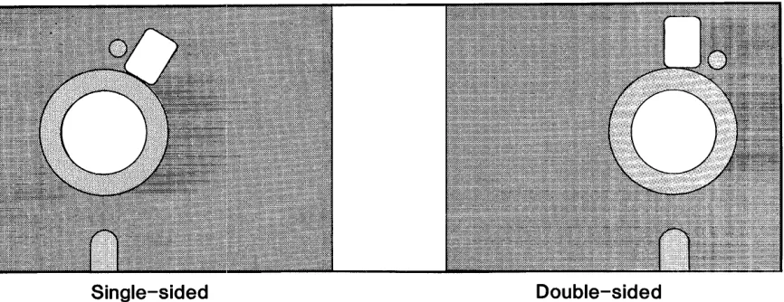
6. Some double-sided diskettes have two holes in their
jackets near the center hole and opposite the
write-protect notch. The drive senses whether the diskette is being used as a one-sided diskette or a double-sided diskette by which hole is covered. Use a write-protect tab to cover the outside hole when using the diskette as a single-sided diskette; cover the inside hole when using i t as a doubled-sided diskette. See Figure 3-1 below.
Single-sided Double-sided
Figure 3-1 Two-holed Double-sided Diskettes
Note: Some models of the Shugart 850 may require both holes of a double-sided diskette to be uncovered when i t
[image:28.612.104.537.411.578.2]THE 2422 ROM RESIDENT FIRMWARE
This chapter contains a description of the bootstrap
loader and the MOSS 2.2 Disk Monitor. It serves two
purposes: 1) to give the background information needed by a
user who wishes to modify the firmwarei 2) to describe how to
use the monitor. Those users who will not be modifying the
firmware may wish to skip the first several sections and begin with Section 4.6.
4.1 COLD-START ENTRY
The cold-start entry point is F000h. If you set a
power-on jump circuit to this address, the CPU will jump to
the cold-start ent.ry point when your system is turned on or
reset. The cold-start initialization routine loads the low
RAM locations called to by the Z-80 restart commands with jump
vectors to the restart error message. It then finds the
highest active RAM address and locates the monitor stack and
work space below it. Next i t checks the state of the Auto
Boot bit (determined by the configuration of the AUTO BOOT
option) in Status Register Ii if the Auto boot bit is 0 the
initialization routine passes control to the bootstrap loader,
which then loads in CP/M as described in section 4.4 below.
The monitor work space is overwritten as CP/M is loaded in.
If the Auto Boot bit is 1, the initialization routine
continues, waiting for a series of carriage returns from the
console device. It uses the carriage returns to synchronize
the baud rate of the 2810 CPU's serial port to the baud rate
of the console device. When i t has done so, i t turns control
4.2 PAGE 0 RAM USED BY FIRMWARE
The following locations in page 0 memory are used by the disk controller firmware. Except where noted, these locations should be reserved exclusively for the firmware's use.
==============================================================
ADDRESS CONTENTS
==============================================================
0000h-0002h
0003h
0008h-000Ah 00l0h-00l2h 00l8h-001Ah 0020h-0022h 0028h-002Ah 0030h-0032h 0038h-003Ah
0040h-0053h
0080h-0l7Fh
These locations contain the warm start vector for the monitor. When CP/M is loaded, they are overwritten by CP/M's warm start vector.
This location contains the Intel Standard IOBYTE loaded during cold start initialization and used by the monitor's basic I/O routines
(see Section 4.4 .. 2).
Called by the Z-80 restart commands, these locations are loaded with jump vectors to the restart error routine (Section 4.6.4) during cold-start initialization. They can be over-written by valid restart routines. Locations 0008h - 000Ah are also used for breakpoint processing by the monitor GO command.
Containing disk parameters used by the monitor and bootstrap loader disk routines, these locations are described in m~re detail in Section 4.3 .. 3.
These locations form a temporary buffer for the Loader program, CCBOOT, read in from disk.
==============================================================
Table 4-1 Low RAM Locations used by Firmware
4.3 THE FIRMWARE DISK ROUTINES
4.3.1 Diskette Format
Track numbering on a diskette begins at its circumference with Track 00 and proceeds toward the center; thus the innermost track on an S" diskette with the standard 77 tracks is Track 76. Each track on side 0 of a double-sided diskette has an associated .track on side 1; these track-pairs are often called cylinders. Unlike track numbering, sector numbering starts with 1, the number given to the first sector immediately following the index pulse. The number of sectors on a track is dependent on disk size, data density, and number of bytes per sector~
The IBM 3740 standard for single-density diskettes allows sector sizes of 12S, 256, and 512 bytes; the System 34 standard for double-density diskettes allow sectors sizes of 256, 512, and 1024 bytes. (The 1793 can format single-density diskettes in 1024-byte sectors and double-density diskettes in 12S-byte sectors as well, but those additional sector sizes have no practical advantage.) Before each sector is an unique address or ID field identifying the track number, diskette side, sector number, and sector size. In addition, the ID fields and data fields must be separated by gaps and sync fields of a minimum length per sector. Figure A-I of Appendix A illustrates the IBM 3740 format standard for single-density
a"
diskettes. The 1793 adds an additional constraint in diskette format: i t expects gaps to consist of minimum number of FFh bytes, followed by several bytes of 00h. Diskettes formatted by a 1771 disk controller chip do not meet the 1793's requirements. Thus the 1793 cannot read such diskettes. (The 1771 can, however, read disks formatted by the 1793.)4.3.2 Description of the Disk Routines
4.3.3 Disk Parameters for Disk Operations
DREAD and DWRITE use locations 0040h-0053h to store the
disk parameters they need. Below are the definitions and
addresses of some of the more important disk parameters:
==============================================================
Address Name Description
==============================================================
0040h
0041h 0042h
0043h
0045h
004Ah
004Ch
004Eh-0053h
DISKNO
TRACK SECTOR
SIDE
TWOSID
CUNIT
HSTBUF
IDSV
Stores the number of the
currently-selected drive: 0, 1, 2, or 3.
Stores the number of the current track.
Stores the number of the current
sector.
Stores the byte written to Control
Register 2 to select disk side. (D0h
=
side 0~ 90h
=
side 1)Stores 0 if the disk in the
currently-selected drive is one-sided~ 1 if i t is
two-sided.
Stores the byte last written to Control
Register 1, giving information on the
currently-selected drive unit.
Stores the starting address in memory
for disk transfers to and from memory.
Stores the ID field information from
the diskette in the current drive.
==============================================================
Table 4-2 Disk Parameters
4.4 THE MONITOR'S I/O ROUTINES
The monitor's basic I/O routines are essentially the same
as those used by CCBIOS, CCS's customized BIOS. They are
designed for a system using CCS's 2810 Z-80 CPU, configured as
described in Section 3.1. As with the primitive disk
routines, they reside in the last 1/2K of the ROM, allowing
them to be available after CP/M is loaded, should you choose
the PR EN (Partion ROM Enable) option. Section 4.4.3 below
contains information on tailoring this portion of the ROM if
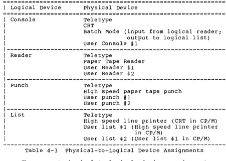
The basic I/O routines in this portion of the ROM implement the IOBYTE function, as developed in the Intel MDS system and as used by CP/M. The IOBYTE function divides peripherals into four categories according to type: Console, typically a teletype or a CRT; Reader, a paper tape reading device; punch, a paper tape punching device; and List, a hard-copy printing device. At any given time, one of four physical devices can be assigned to each of the logical device categories. Table 4-3 below lists the allowable physical devices in each logical device category.
==============================================================
I
Logical Device physical Device==============================================================
Console
Reader
Punch
List
Teletype CRT
Batch Mode (input from logical reader; output to logical list) User Console #1
Teletype
paper Tape Reader User Reader #1 User Reader #2
Teletype
High speed paper tape punch User punch #1
User punch #2
Teletype
High speed line printer (CRT in CP/M) User list #1 (High speed line printer
in CP/M)
User list #2 (user list #1 in CP/M)
Table 4-3 Physical-to-Logical Device Assignments
[image:33.618.86.538.281.604.2]which is the default assignment. These routines are designed
to drive the serial port on the 2810 CPU. Please note that
the physical assignment names do not have to accurately
describe the actual peripheral used; the actual physical
device driven by the teletype assignment routines could easily
be a CRT. The driver routines associated with the remaining
physical device assignments are set equal to the I/O error
routine. Thus if an unsupported physical device is assigned
to a logical device, the I/O error message will be displayed
and control returned to the monitor whenever an I/O operation
involving the logical device is attempted.
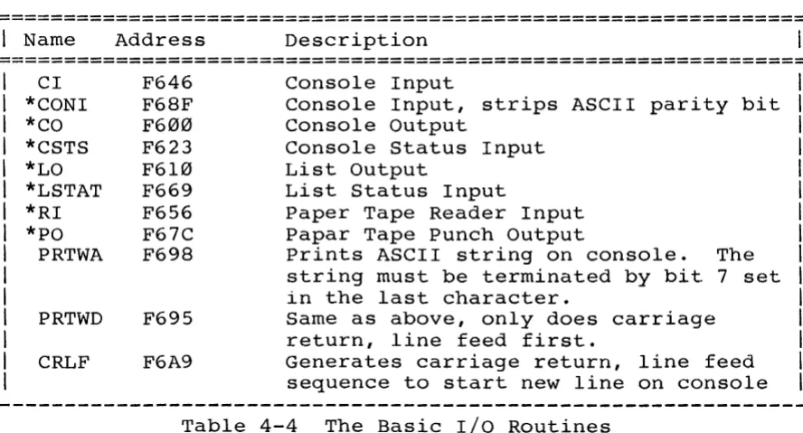
4.4.2 The Basic I/O Routines
The user may call the following basic I/O routines from
his own programs while in the monitor or from his own
customized BIOS if the PR EN option is enabled.
==============================================================
I
Name Address Description==============================================================
CI *CONI *CO *CSTS *LO *LSTAT *RI *PO
PRTWA
PRTWD
CRLF
F646 F68F F600 F623 F610 F669 F656 F67C F698
F695
F6A9
Console Input
Console Input, strips ASCII parity bit Console Output
Console Status Input List Output
List Status Input
Paper Tape Reader Input Papar Tape Punch Output
Prints ASCII string on console. The
string must be terminated by bit 7 set in the last character.
Same as above, only does carriage return, line feed first.
Generates carriage return, line feed sequence to start new line on console
Table 4-4 The Basic I/O Routines
The starred routines are CP/M compatible routines, basically
the the same as the following routines used in CCBIOS: CONIN,
CONOUT, CONST, LIST, LISTST, READER, and PUNCH. They perform
the basic IOBYTE handling as described above. Again, actual
driver routines exist only for the teletype assignment for
each logical category. These driver routines conform to the
CP/M calling conventions, passing the data in the C register
for any output and in the A register for any input. PRTWA,
[image:34.613.95.539.343.582.2]routines which are available as long as the of the ROM is accessible. CI is an input routine which does not strip the they are useful
Basic I/O portion alternative console parity bit.
4.4.3 Customizing the Basic I/O Routines
As mentioned before, only the teletype physical device assignment is supported by the firmware. The teletype drivers are designed to drive the console port on the 2810 2-80 CPU. Should you wish modify the console drivers to work with another console port, you will thus have to modify the teletype driver routines (TTST, TTYIN, TTOST, and TTYOUT) routines in the source code. Since the teletype device is the default console device, you need also to change the console initialization code.
To add a peripheral device, you generally need only to replace the equate to IOER in the physical device drivers with valid driver code. The equates for additional peripheral devices are on page C-24 of the firmware listing in Appendix
c.
Should you wish to add a printer, for example, that is selected by the high speed line printer assignment, you would change the equatesLPRT: EQU LPRST: EQU
IOER IOER
iUNASSIGNED LINE PRINTER
iUNASSIGNED LINE PRINTER STATUS
to driver code while preserving the routines' names. Only if you wish your printer to be selected by the default teletype assignment is it necessary to alter the basic I/O routines themselves. In that case, the basic I/O routines LO and LSTAT should be modified so that the jumps to TTYOUT and TTOST which are made when the teletype device is selected are replaced with jumps to user-named and user-written printer output and status routines. Note that in the case of the Punch and Reader devices, there are no basic I/O status routines. The necessary status routines must be called by the input or output drivers.
The firmware may also be modified for different drive step rates. Currently, the step rates are 30ms for 5.25" drives and 10ms for 8" drives. To change the step rates, modify the following fragment of code (page C-27 the firmware
SET1: RAL
LXI MVI
MOV MVI
D,STPRAT A,3
M,A A,2
;SET THE INITIAL STEP RATE ;TO SLOWEST POSSIBLE
(replace 3 with
o
for 6ms step rate 1 for l2ms step rate 2 for 20ms step rate);SET MAXI STEP RATE (replace 2 with
o
for 3ms step rate 1 for 6ms step rate 3 for ISms step rate)The method of modifying the firmware so far described involves programming a user-supplied 2716 EPROM with the modified code and replacing the CCS ROM with it. It is also possible, however, to modify the firmware using memory overlay techniques. Since the 2422 generates, but does not receive, the PHANTOM signal, its ROM has to be moved to the CPU board. There the selected portions of the firmware can be overlaid by a peripheral board generating the PHANTOM signal. For example, instead of replacing the equates LPRT and LPRST with drive code, the jump instructions to LPRT and LPRST routines in the basic I/O routines LO and LSTAT can be overlaid with jump instructions to printer driver routines in the peripheral board's ROM.
4.5 THE BOOTSTRAP LOADER
on system power-on or reset (AUTO BOOT shorting plug in
place), your system will "hang." When i t is finished reading
in the Loader program, the bootstrap loader leaves some disk
parameters in memory:
---I
NAME VALUE=======================================================
DISKNO 0
SIDE 0
TRACK 00
SECTOR 3
CUNIT 21 for a single-density mini diskette
31 for a single-density 8" diskette 61 for a double-density mini diskette
IDSV + 3 00 if diskette sector size is 128
01 if diskette sector size is 256 02 if diskette sector size is 512 03 if diskette sector size is 1024
=======================================================
Table 4-5 Disk Parameters after Boot
After i t is loaded, the CCBOOT outputs hex 01 to port 40h. If
pins 2 and 3 of the ROM ENABLE jumper have been shorted, this
simultaneously disables the bootstrap and monitor firmware and enables any RAM assigned to bank 0 and with a bank select port of 40h.
4.6 THE MONITOR
CCS's MOSS 2.2 Disk Monitor is designed to allow you to
control a system using a 2810 Z-80 CPU from the console
keyboard. It allows you to display a block of memory in hex
and ASCII, to move, change, and verify memory, and to transfer
control to a program in memory with breakpoints set. You can
also input or output a data byte to or from any I/O port and
command the monitor to read and write floppy disks.
For the MOSS 2.2 Monitor to work exactly as described
below, your 2422 Disk Controller board and 2810 Z-80 CPU must
4.6.1 The Monitor's Memory Space
In addition to the memory the ROM occupies (F000h-F800h)
and the page 0 addresses specified in Section 4.2, the monitor
requires some high RAM locations for the system stack and
temporary storage area. The monitor scans the available
memory until i t finds the highest active RAM address and then
counts down 56 bytes to store the breakpoints, registers, and
register restoring routine. It locates the system stack below
that: you should reserve at least 88 bytes of high RAM memory
for the monitor's use.
4.6.2 Bringing up the Monitor
To enter the monitor, turn your system on or reset it.
If the AUTO BOOT shorting plug has been removed, this results
automatically in a cold-start entry into the monitor. Set
your terminal to the baud rate at which you wish to operate.
You have a choice of any baud rate between 2 and 56K baud.
Hit the carriage return key until the monitor responds with
MOSS VERS 2.2
The maximum number of carriage returns needed before the
monitor responds is three. This series of carriage returns
allows the baud rate of the 2810's serial port to be
initialized to your console baud rate. \ihen the monitor
prompt appears, you may start entering commands.
4.6.3 Monitor Command Format
The MOSS Monitor commands must conform to a specific
format. The general form is
-Cel e2 e3
where - is the prompt, C is the command
are the address and data entries, if any. of a command are as follows:
character and el-e3
THE COMMAND CHARACTER: The monitor is controlled by
one-character commands entered from the keyboard in
response to the monitor prompt, a dash (-). No space is
allowed between the prompt and the command character.
ADDRESS AND DATA ENTRIES: The general form for an
address is a four digit hex number; for a data byte, a
two digit hex number. Leading zeros need not be
entered; the monitor will supply them. No space is
allowed between the command character and the first
address or data entry. Subsequent entries must be
separated by a delimiter. The monitor looks at only the
last four address characters or last two data characters
before a delimiter. So if you make a mistake while
typing an entry, keep typing until the last two or four
characters are correct, depending on whether i t is an
address or data entry.
DELIMITERS: The MOSS Monitor recognizes three
delimiters: a carriage return [CR], a space, or a
comma. A carriage return indicates to the monitor that
the current comnland is complete and should be executed.
Either a space or a comma can mark the end of an address
or data entry. In our command examples we will
generally use a space as a delimiter, unless a comma
makes the command form clearer. Please note, however,
that you can use the space and the comma
interchangeably. In certain commands a space or a comma
can also be interchanged with a carriage return. These
are commands for which the Monitor expects a fixed
number of entries (and hence delimiters) following the
command character.
SAMPLE COMMAND
The following commands to display the block of memory
0FFBh to 100Ah are all equivalent. Although the spacing is
not free-form, some variety in the command form is allowed.
Note that the display command requires two and only two
address parameters, so that the last delimiter can be a comma
or a space as well as a carriage return.
-D0FFB 100A[CR] -DFFB,100A, -DFFB,100A[CR] -DFFB 100A[space]
4.6.4 Error Messages
The MOSS monitor detects four types of error conditions
and responds with a different error message for each. They
are as follows:
COMMAND ERROR: Should you make an invalid entry, the
command will be aborted, a warm boot of the system will
occur, and the error message
1?11
will be printed, followed by the monitor prompt.
I/O ASSIGNMENT ERROR: As described in Section 4.605.1,
the Assign command allows you to assign a physical
device to a logical peripheral category. When an I/O
routine involving the logical category is called, the
CPU will jump to the driver routine indicated by the
physical assignment. If there is no driver routine, i t
will jump instead to the I/O Assignment Error routine.
This routine sets the IOBYTE to its default value,
outputs the error message
I/O ERR
and does a warm boot of the system.
RESTART ERROR: During cold-start initialization,
jump-vectors to a restart error mes~age are loaded in
the memory locations called by the Z-80 restart
instructions. This prevents a jump to a restart address
without code. A restart error causes the display of the
message
RST ERR
and a warm boot of the system.
DISK ERROR: The monitor, when executing the Read,
Write, or Boot commands, will output the following error
message and status information if i t is unable to
execute the command:
The first three hex bytes identify which physical record
the monitor was unable to read or write. U gives the
unit or drive number (0-3), T the track number, and S
the sector number of the record where the error occured.
C and E give the operation status a~ the time of the
error. They reflect the contents of two of the 1793's
internal registers: C shows the last command loaded in
the Command register; E gives the contents of the Status
register. See the 1793 data sheet for a description of
these registers' contents.
4.6.5 The Monitor Commands
4.6.5.1 Assign (A)
The Assign command supports the IOBYTE function described
in Section 4.4.1. It allows you to change the
physical-to-logical device assignments and thus choose the
peripherals you wish to work with while in the monitor. To
assign a physical device to a logical device category, enter
-Ax
~1here x equals either C,R,P, or L, the logical device codes.
If you enter a character other than these four, the computer
~1ill return with 1111 and another prompt. If you enter a
valid logical device code, the computer will return
immediately with the prompt. Enter the physical device code
following the prompt. Should you enter a delimiter only or a
nonvalid device code, the device assignment will default to
t.he previous assignment. Table 4-6 below summarizes the
physical and logical device codes. Refer to Table 4-3 for the
allowable physical device assignments for each logical device.
======================================================
I
LOGICAL DEVICE PHYSICAL DEVICE======================================================
I
I
I
I
I
I
I
I
Console=C Reader=R Punch=P List=L
Teletype=T CRT=C·
Batch Mode=B
Paper Tape.Reader=P Paper Tape Punch=P
High Speed Line Printer=L User Device #1=1
User Device #2=2
======================================================