VIBRATION ANALYSIS USING EXPERIMENTAL DATA A N D APPROXIMATE METHODS W I T H CONSIDERATION OF P O W E R
FLOW FROM MACHINERY INTO BUILT-UP STRUCTURES
b y
Hugh George David Goyder
Institute of Sound and Vibration Research Faculty of Engineering and Applied Science
University of Southampton
Thesis submitted for the Degree of
Doctor of Philosophy
A p r i l , 1978.
University of Southampton
Abstract
Faculty of Engineering and Applied Science
Doctor of Philosophy
VIBRATION ANALYSIS USING EXPERIMENTAL DATA A N D APPROXIMATE METHODS WITH CONSIDERATION OF POWER
FLOW FROM MACHINERY INTO BUILT-UP STRUCTURES by Hugh George David Goyder
Typical built-up structures consist of beams, plates and beam-stiffened plates. Due to strong coupling with other parts of the structure the vibrational characteristics of these components are too complicated to be analysed exactly. However, the vibration may be approximated by the response of structures with a similar cross section and of infinite length. The wave propagation and power flow due to force and torque
(moment) excitation has been studied at the driving point and in the far field for infinite beams, plates and beam stiffened plates.
An infinite, beam-stiffened plate excited by forces or torques applied to the beam behaves like an uncoupled beam at the driving point. In the far field, power transmitted by flexural waves in the beam is radiated into the plate whilst power transmitted by torsional waves in the beam is not radiated. The plate carries a cylindrical wave with a strong
directivity.
The power flowing through the isolators and into the supporting founda-tion of a machine has been examined by approximating the driving point frequency response function of the foundation. One and two stage isolation of machines with internal force or velocity sources has been considered. Two stage isolation is superior to single stage isolation in reducing power flow, in those circumstances where the excitation spectra do not cover the two resonances of the system.
A structure with a number of resonances is difficult to analyse theoreti-cally but may be investigated from measured data. By exciting a structure at one point and measuring the frequency response at a number of positions it is possible to construct a mathematical model of the structure. The model is valuable because it enables unmeasured frequency response
functions to be predicted. Also, by modelling two separate components of a structure from measured data it is possible to obtain an estimate of
ACKNOWLEDGEMENTS
CONTENTS
LIST OF SYllBOLS
CHAPTER 1 INTRODUCTION Introduction
The Principal Methods of Vibration Analysis Objectives of this Work
Conventions and Definitions PART ONE
CHAPTER 2 WAVE PROPAGATION AND POWER FLOW IN INFINITE BEAMS
1.1
1 . 2
1.3 1.4
2 . 1
2 . 2
2.3 2.4 2.5
2 . 6
2.72 . 8
Introduction
Torsional and Longitudinal Wave Motion in Beams Power Flow in Torsional Wave Motion
Flexural Wave Motion in Beams Force Excitation of a Uniform Beam
Power Flow in a Uniform Beam with Force Excitation Torque Excitation of a Uniform Beam
Power Flow in a Uniform Beam with Torque Excitation
Page
1
1
2 4 4 8 9 911
13 14 1416
1920
CHAPTER 3 FLEXURAL W A V E PROPAGATION AND POi'JER FLOW IN PLATES 3.1 Introduction
3.2 Flexural Vibration of an Infinite Uniform Plate Driven by a Transverse Driving Force
3.3 The Response at the Driving Point of a Plate with Force Excitation
3.4 The Response in the Far Field of a Plate with Force Excitation
3.5 Power Flow Intensity Due to Cylindrical Waves in a Plate
3.6 Power Flow in a Plate with Force Excitation
3.7 Flexural Vibrations of an Infinite Uniform Plate Due to Torque Excitation
3.8 The Response in the Far Field of a Plate with Torque Excitation
3.9 Power Flow in a Plate with Torque Excitation
3.10 A Comparison Between Finite and Infinite Structures
Page CHAPTER 4
4.1 4.2 4.3 4.4 4.5 4.6 4.7 4.8 4.9
WAVE PROPAGATION AND POWER FLOW IN BEAM-STIFFENED PLATES
Introduction
Formulation of the Equations for the Response of an Infinite Plate Stiffened by an Infinite Beam
Force Excitation of an Infinite Beam-stiffened Plate Power Flow in Beam-stiffened Plates with Force
Excitation
Torque Excitation of an Infinite Beamstiffened Plate -Symmetrical Motion
Power Flow in Beam-stiffened Plates with Symmetrical Torque Excitation
Torque Excitation of an Infinite Beamstiffened Plate -Asjnimietrical Motion
The Response in the Far-field of a Beam-stiffened Plate with Asymmetrical Torque Excitation
Power Flow in a Beam-stiffened Plate with Asymmetrical Torque Isolation
40 40 41 44 50 52 56 57 64
66
CHAPTER 5 POWER FLOW THROUGH ISOLATORS 5.1 5.2 5.3 5.4 5.5 5.6 5.7 5.8 Introduction
Power Flow into the Structure
Single Stage Isolation of a Rigid Machine with a Force Source
Two Stage Isolation of a Rigid Machine with a Force Source by means of a Blocking Mass
Single Stage Isolation of a Machine with a Velocity Source
Two Stage Isolation of a Machine with a Velocity Source Power Flow Due to a Band Limited Excitation Spectrum Selection of Foundations and Isolators
68
68
69 71 74 76 77 7882
PART TWO
CHAPTER 6 STRUCTURAL MODELLING BY THE CURVE FITTING OF MEASURED FREQUENCY RESPONSE DATA
6.1 Introduction
6.2 Formulation of the Equations for the Frequency Response of a Structure
6.3 The Measurement of a Complete Frequency Response Matrix
86
86
Page
6.4 Methods of Mathematical Modelling 92
6.5 Curve Fitting to Measured Frequency Response Data 94
6.6 Examples of Curve Fitting 99
6.7 Methods of Modelling when Some of the Properties of
the Structure are Known 102
CHAPTER 7 APPLICATIONS OF MATHEMATICAL MODELLING 105
7.1 Introduction 105
7.2 The Distribution of Mass Stiffness and Damping
within a Structure 105
7.3 The Response of a Structure Predicted from its
Constituent Components 107
7.4 Errors in System Coupling Methods 108
7.5 Measurement of Power Flow between Connected Components 110
PART THREE
112
CHAPTER 8 CONCLUSIONS REFERENCES
113
TABLE I. Properties of infinite system.
TABLE II. Power flow into foundations from machinery sources on isolators.
TABLE III. Velocities of components of isolation systems. FIGURES
APPENDIX I The equations of motion for torsional waves including an excitation function
APPENDIX II The equation of motion of flexural waves in beams including excitation functions
APPENDIX III The equation of motion for flexural waves in plates including excitation functions
APPENDIX IV Details of the contour integration of equation (4.34) APPENDIX V The frequency response of a damped structure
[image:6.595.67.550.60.754.2]LIST OF SYMBOLS
A Cross sectional area of beam; B
= 7;^ ratio of plate bending stiffness to beam torsional yv
stiffness (Chapters 2-4); Constant (Chapter 5) B Bending stiffness
D Damping matrix
E Young's modulus
F Force or pressure
G Shear modulus
H Frequency response matrix I Second moment of area
; Ig Integrals
J Polar mass moment of inertia per unit length K Stiffness matrix (Chapter 6)
Stiffness of isolator
L Parameter from reference [12]
M Bending moment
Mass of machine (Chapter 5) Mass matrix (Chapter 6)
P Power
P Power flow at station a a
Pg Power supplied by source P ^ Power associated with shear P ^ power associated with bending Q Torsion constant
Qg Power flow transmission spectrum for a force source Power flow transmission spectrum for a velocity source
T Torque
Tp Total power flow
a Radius of disc over which torque applied to plate acts e 2.718 ... Base of natural logarithm
f (subscript) flexural wave motion i Imaginary operator ( / ^ ) ;
k Uavenumber
£ (subscript) longitudinal wave motion n number of resonance frequencies
p Pole position
r, d) Polar coordinates
s Ratio of beam to plate wave numbers ( = — ) (Chapter 4) Exponent of frequency dependence (Chapter ^ 5)
Number of response stations (Chapter 6)
t Time
(subscript) torsional wave motion
u shear force
V Velocity
X, y, z Coordinates in Cartesian space
a Coordinate in wavenumber space g Mobility of subsystem
Y, (5 Normalised real and imaginary parts of mobility r Integration path
6 Dirac delta function o
n Loss factor
8 Angular displacement
V Poisson's ratio
g Displacement
^ Imaginary component of flexural wavenumber K(1 + ig)
TT 3.1415...
p Density
(}) Phase angle
\j) Eigenvector
CHAPTER 1 INTRODUCTION
1.1 Introduction
Typical built-up structures such as buildings or ships are an assembly of many different components all of which interact strongly when set into vibration. Certain components such as beams or plates are relatively easy to analyse individually when there is no coupling with other elements. However, when built into a structure the vibration of a component is strongly dependent on the other elements to which it is attached and the calculation of the motion becomes very complicated or even impossible. In order to obtain some widely applicable formulae, methods of vibration analysis based on approximate or measurement methods are developed in this thesis.
In a built-up structure a common source of vibration is a machinery installation which, due to some internal excitation, injects vibrational energy into its supporting foundations. This energy is carried by w a v e motion within the foundation until some boundary or discontinuity is encountered. Here some of the energy in the wave w i l l be reflected back into the foundation the remainder being transmitted through the boundaries to other parts of the structure. If a significant amount of energy is reflected to and fro w i t h i n the foundation then resonances will occur at those frequencies for w h i c h the w a v e motion interferes construc-tively. The power w h i c h is transmitted through the boundaries of the foundation is available for radiation or as unwanted vibration in the remaining portion of the structure and this is a significant problem. A direct approach for controlling the unwanted power is to minimise the net vibratory power flow into the foundation at the source. The use of power flow in calculations is very valuable because it combines both
forces and velocities in a single concept. An attempt to decrease the radiation or vibration in a structure b y reducing only the force or velocity may not necessarily be successful. However, an improvement may be ensured by decreasing the net vibrational power applied to a
The foundation of a machine is a crucial component since it is responsible for the conversion of the machinery excitation into propa-gating wave motion. Therefore the first part of this thesis is a study of w a v e motion and power flow in a range of common foundations such as beams, plates and beam-stiffened plates. The existence of damping and of a large n u m b e r of resonances enables foundations to be approximated by components of infinite extent. This is equivalent to assuming that at the boundaries of the foundation there are no reflections and all power is propagated away. This approach greatly assists the analysis and, in particular, enables the power flow into the structure due to different types of excitation to be derived. Having established the behaviour of the foundation the reduction in power flow resulting from
the isolation of machinery may be estimated. W h e n there are significant reflections from boundaries and individual resonances are apparent, the theoretical approach described above becomes less accurate. Consequently the second part of this thesis is concerned w i t h those frequency ranges w h e r e there is resonant behaviour of the structure. Starting with measured data computer based procedures are formulated w h i c h enable mathematical models of the structure to be formed. The models may be used to predict unmeasured responses thus greatly reducing the experi-mental testing time required. Other applications of the mathematical model are also considered. In particular, the possibility of modelling
two components and then predicting their behaviour w h e n joined is examined critically.
1.2 The Principal Methods of Vibration Analysis
An exact solution for the vibration of a structure may be obtained by forming the differential equations for the motion and solving them
for the appropriate boundary conditions. It is useful to obtein the harmonic response since, if the structure is linear, then the response due to transient or periodic excitation may then be determined exactly by means of a Fourier transform. The calculations involved in a
structure; this procedure is usually described as modal analysis.
The complexity of a practical structure unfortunately prevents this type of detailed analysis because it is not possible to formulate and solve all the differential equations. Even relatively simple components are difficult to analyse if they are built into a structure in such a manner that the boundary conditions cannot be determined. However when a structure has several components the response of the entire structure may be calculated from the response of the individual components. If many components are involved, procedures of this type (often known as mobility or receptance methods) become unwieldy. Consequently only relatively simple structures may be analysed exactly to obtain the res-ponse of a prescribed excitation.
Various approximate methods, each appropriate to different circum-stances, enable a w i d e range of vibration problems to be solved. If the effect of the boundaries is considered to be unimportant then the
structure may be approximated by considering it to be of infinite length. This type of analysis is usually formulated in terms of wave motion. If a structure has w e l l defined mass and stiffness elements then an
approximate mathematical model can be formulated and solved in which there are pure mass elements and pure stiffness elements. Both these types of approximate analysis are used in Part One of this thesis.
An approximate method which is capable of great accuracy in the finite element method. In this procedure the structure is divided into a number of elements each element having a certain deformation pattern. By considering the strain and kinetic energies of the structure the resonance frequencies and modes of vibration may be calculated. The deformation is built-up out of the deformation of the individual elements; consequently the emphasis in the analysis is centred on determinir^ the deformation of elements rather than the deformation of the entire structure, A finite element analysis may onxy be applied to particular problems and will only produce numerical results. Because of the complexity of a
practical built-up structure detailed representation of individual compo-nents is not generally possible but an overall response may be determined.
finite element method is not suitable for h i g h frequencies w h e n there are many resonances. In this regime statistical energy analysis is m o r e appropriate. This is an approximate method used for analysing the interaction between two components. W h e n there are many resonances present in the components of a system then averaged properties may be used to predict an averaged response of the coupled system. The average modal energies of each system must be known together with the nature of
the coupling. This type of analysis is generally only appropriate w h e n both the components being considered have a high modal density and the coupling can be calculated or estimated.
By combining measured data w i t h theoretical data it is possible to obtain information about a complicated structure. This type of analysis is considered in Part Two of this thesis.
1.3 Objectives of This Work
The aim of this study is to formulate and evaluate methods for the vibration analysis of complicated practical built-up structures. To
this end a theoretical study of commonly occurring components of struc-tures is commenced with the aim of determining simple widely applicable general formulae w h i c h indicate trends of behaviour and give approximate solutions. In particular this approach is to be applied to the problem of machinery isolation where it is considered that the use of power flow should provide a unifying concept.
A further intention is to establish procedures b y which the fundamental n a t u r e of an existing structure may be determined from measured data.
1.4 Conventions and Definitions
There a r e two conventions for describing a harmonic w a v e propagating in the positive x-direction. These conventions are either
^i(kK - »t) (1.1)
or
The first convention (1.1) gives a positive w a v e n u m b e r for motion in the positive x-direction but negative frequency dependence. This convention w i l l b e used w h e n considering the spatial response of a
structure. The second convention (1.2) gives a positive frequency dependence w i t h negative w a v e numbers and is more suitable for describ-ing the frequency response of a structure. Care w i l l be taken to state which convention is b e i n g employed in any problem and in particular all tables w i l l use the second convention. To convert from one convention to the other it is merely necessary to replace every i (= in an equation by - i .
Power is the rate at which w o r k is done and is given by the relationship
P. = F.V. (1-3)
X
11
w h e r e and are the instantaneous values of force and velocity at a point. (Instantaneous values w i l l b e indicated b y the subscript i.) W h e n power flows through an area it is necessary to consider it as an
intensity and therefore w i t h the force determined as a stress. With a vibrating structure the net flow of power is more important than
the instantaneous value and w h e n force and velocity are harmonic this is given by
2n/w
. f = 2¥
f V l
(1-*)
O
where to is the frequency of vibration. If the force and velocity are written
as:-F. . V. .
then:-p = ||v|
|F|
COS <})or P = ^Re{FV*} = ^Re{F*V} ( 1 . 5 )
= i[Re{F}Re{V} + Im{F}lm{V}]
w h e r e <J) is the phase angle and * denotes the complex conjugate. The ratio of the complex harmonic velocity to the complex harmonic force is the mobility and this quantity is a property of the structure alone.
One may substitute therefore for either the force or the velocity to give;
P - - !|v|^ M M (1.6,
where g = ^ .
These formulae hold for both conventions of e"^^^ and
It is convenient to represent damping in a structure b y means of a c o m p l e x Young's modulus [l] , The relationship between stress and strain may b e w r i t t e n
as;-Stress
E ( 1 + in) for e^^^ frequency dependence Strain
E (1 - in) for e frequency dependence
w h e r e E is the Young's modulus and n is the loss factor for the material. This representation of damping leads to a complex resonance frequency and a complex w a v e n u m b e r . If a structure has an undamped resonance at % then the introduction of damping leads to a resonance frequency
of:-* ~2^ frequency dependence (1.7)
2^ e frequency dependence (1.8)
-~ 2^ ® frequency dependence (1.9)
k ( l + — j ) for e frequency dependence (1.10)
Similarly for flexural waves, the wavenumber is proportional to (—)^;
therefore it may be w r i t t e n as:- ^
~ ® frequency dependence (1.11)
C H A P T E R 2
W A V E PROPAGATION A N D P O W E R FLOW IN BEAMS A N D PLATES
2.1 Introduction
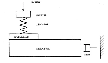
Problems in vibration isolation may be considerably simplified b y considering the vibrational power flow in a structure. A typical problem is idealized by figure 2.1. Power is injected into a structure such as a b u i l d i n g or ship b y a machine w i t h an internal vibration source, w h i c h is mounted on an isolator. Due to the isolator foundation b e i n g flexible, power is transmitted through the structure to the sink where it appears as unwanted vibration or radiation.
The aim of vibration isolation procedures is to reduce the velocity amplitudes at the sink b y m a k i n g appropriate modifications to the isolator and isolator foundation. A direct approach w o u l d therefore be to
calculate the response at the sink due to an excitation at the source and to design the isolator, foundation and structure to minimise the unwanted vibration. Because of the variety of possible structures and because of their often complicated nature, direct calculations of this type are extremely difficult. In addition, an exact description of the unwanted vibration cannot always be formulated, especially in the case of radiation for w h i c h the velocity distribution over the surface of the structure must be e s t a b l i s h e d .
Standard methods of vibration isolation (for example [l,2,3,4] ) therefore simplify the p r o b l e m b y only analysing the reduction of force or velocity at the foundation.
An approach to vibration isolation may be formulated by considering the power flowing into the structure at the m o u n t i n g point of the isolator. If the isolator and foundation are designed to minimise this power flow then all unwanted vibration w i l l b e minimised.
The power that enters a structure is a function of the characteristics of the source, isolator and foundation. The isolator and source are
simplified according to the method developed by Skudrzyk £5j . This method allows a finite damped structure to be approximated b y an e q u i v a
-lent structure of infinite extent w i t h no reflecting devices. Thus it is assumed that waves propagating away from the source are attenuated b y damping or radiation and are not reflected b a c k to the source to form
standing w a v e s . Alternatively, this is equivalent to assuming that there are many modes of vibration contributing to the motion at any one
frequency without one mode being dominant.
A n u m b e r of typical foundations such as b e a m s , plates and b e a m
-stiffened plates h a v e therefore been analysed as if they w e r e of infinite extent. W a v e propagation in these types of structure has b e e n studied previously by many authors; h o w e v e r , except for H e c k l [6] , Cremer, Heckl and Ungar , N o i s e u x and Pavic [9] there has b e e n little detailed consideration of power flow. In the following chapters the power flowing into each infinite foundation due to a point source and the subsequent flow of power throughout the structure are given. As foundations may be excited b y forces or torques, both these types of source have b e e n considered. The results are summarised for the simpler foundations in Table I.
A unified approach has been adopted for analysing the various infinite structures. In each case a w a v e equation has been derived in a right handed coordinate system w i t h a source applied as a spatial
delta function (written 6^). Harmonic time dependence of the form e ^ ^ is assumed giving a linear differential equation in one or two dimensions. By applying a spatial Fourier transform the differential equation is
transformed into an algebraic equation in wavenuniber space. The solution is obtained by taking the inverse Fourier transform, the integral b e i n g evaluated by contour integration. These procedures are described in references [lO,l]Q . The definition of the Fourier transform used
is:-5(a) = I g(y)e ^"•''dy (2.1)
and the inversion integral
A over a function represents the transform of that function and the coordinate in w a v e n u m b e r space w i l l be denoted by a . In the twodimensional case the Fourier transform w i l l be w r i t t e n a s :
-OO 00 .
/ f
-lO-X
-lOyY
° y ) = [c(x, y)e e dxdy (2.3)
and the inversion integral
as:-~ id X ia y CO 00
2 f f % la X la y
» y) =-JJT J J
V ®
* ^ ^
(2.4)
S(x
4Tr
2.2 Torsional and Longitudinal Wave M o t i o n in Beams
Since torsional and longitudinal w a v e s both obey the same second order differential equation, results obtained b y examining torsional w a v e s are also applicable to longitudinal w a v e s . Torsional w a v e s w i l l b e considered here because of the two this type of w a v e motion is
generally more important.
Figure 2.2 shows an infinite b e a m w i t h shear modulus G, torsion constant Q and mass moment of inertia per unit length J. The b e a m lies along the y axis w i t h a torque of amplitude Te applied at y = 0. T h e angular displacement at any point is given by 8(y). The equation of motion is derived in A p p e n d i x I and
is:-3^8. 9^8.
J
i = GQ
1 + Te'iwCg
(2.5)
9t 9y °
This equation assumes that the torsional wavelengths are greater tb£in the cross section dimensions of the b e a m .
A s s u m i n g h a r m o n i c time dependence of the form e this equation may b e w r i t t e n
as:-• ^ 2 " • - i p 'o (2.6)
2 co^J
angular displacement. The equivalent equation for longitudinal waves
is:-- % E (2.7)
2 2
w h e r e and S(y) is the displacement, A the cross sectional area, E the Young's modulus and F the applied force. Only torsional waves will be considered below but to convert the results for longitudinal waves the equivalent terms in equations (2.7) and (2.6) may be interchanged.
The Fourier transform (equation (2.1)) in the y-direction
gives:-k / - .2
( 2 . 8 )
The solution is given b y the inverse Fourier transform o f equation (2.8) and is:^
8(y) - T
2irGQ ~ 2 2
kf - *
da. (2.9)
This integral has two poles at ot = 2 which are shown together with the integration contour in figure 2.3. The contour is deformed to pass beneath the pole at c*. = +k^ since with the inclusion of damping this pole w o u l d lie above the real axis. The pole at a = - k is not included in the contour since this pole with damping would lie beneath the real axis.
ik^y
The residue of the integral is — and the solution is therefore: —
• # % ik^y
or in terms of mobility with e
-iw8
't -icjt
we ik^y
(2.10)
2GQk^
frequency dependence:-ik^y
2 / ^ 7
(2.11)
2 . 3 Power Flow in Torsional Wave Motion
Using equation (1.6) for the power supplied to a structure
gives;-fx I ^
where denotes the power supplied b y a source.
The power flow at any station along the b e a m is given b y equation (1.5). The angular velocity is
„ i(k V - oit)
internal twisting moment is given b y ! ~
^®i T i(k^r-wt) 3y'
*i - - G Q a ; - - 2 *
denoting the power at any station b y P^ gives
IT
a
, 2
Pg IS h a l f the power supplied by the source, the remaining power going in the negative y-direction. If damping is included then both and G become c o m p l e x and so therefore do L and M ^ . Writing G as G(1 - in), as k^(l + i ^ ) and only including terms in n to first order gives
T 2 - k ^ n y
The power is therefore seen to decay exponentially with distance from the source.
2.4 Flexural Wave Motion in Beams
Iftilike other wave types, flexural waves cause two internal forces to act in a beam. As will be shown these two forces (one associated with bending, the other with shear) are both important since they carry equal amounts of power in the far field. In the near field, in addition
to propagating waves, non propagating waves couple the two forces accord-ing to the particular boundary conditions imposed. In addition, flexural waves are dispersive being represented by a fourth order differential equation in which the wave speed is proportional to the square root of frequency. The differential equation for a beam including sources due to force and torque excitation is given in Appendix II.
In deriving the equation of motion no account has been taken of the effects of rotary inertia and shear deformation. It is assumed that the wavelengths of the propagating flexural waves are always greater than
the cross—sectional dimensions of the beam in the frequency range of interest.
2.5 Force Excitation of a Iftiiform Beam
Figure 2.4 shows an infinite uniform beam of density p, cross-sectional area A, second moment of area I and Young's modulus E, laying along the y-axis. A harmonic force of amplitude Fe~^'^^6 i applied at the origin y = 0. The differential equation representing the motion is derived in Appendix II and for harmonic time dependence of the form e
is:-.4p ^
7 4 - ^ ^ = 1 1 ^ 0 (2.15)
dy 2 4 _ 0) pA
where k = g j and 5(y) is the displacement in the z-direction. Taking the spatial Fourier transform in the y—direction
gives:-- I t 4 \ 4 (2.16)
a - k
namely:-F
f
Iriil J " 4 7 5 " ^ " (2.17) •' a - k
This equation has four poles (a = jfk and a = H k ) w h i c h are shown on figure 2.5 together with the contour of integration. The contour has once again been indented to include only those poles which correspond to sources. The residue due to the pole at a = +k is e^^^/4k^ and the residue at a = +ik is e ^^/-4ik^. The solution for x ^ 0 is therefore:
6(y) -
-? Le ^ + ie 'J (2.18)AEIk
The instantaneous values of the transverse velocity and angular velocity for frequency dependence of the form e"^^^
are:-k A y } . _ - j % L + le-ky] (2.19)
4EIk and
e.(y) . - I I H [elk? _ e-ky] e - i " : (2.20) 4EIk
where 9^ is the instantaneous angular velocity. The point mobility at the origin between the driving force and the transverse velocity is
therefore:-B = 3 (1 + i) = (2.21)
4EIk^ 4 p A v C
This mobility decreases with increasing frequency and behaves at any frequency like a dashpot and mass in parallel.
The transfer mobility between the driving force and angular velocity may be found from equation (2.20). This mobility is clearly zero at the origin as w o u l d be expected from symmetry.
wavelength it may be seen that at a distance of one wavelength from the source it has decreased to less than 0.2% of its value at the origin. Therefore for large values of k y the real exponential terms may be
ignored in equations (2.19) and (2.20) leaving only the complex exponentials,
2.6 Power Flow in a Uniform Beam with Force Excitation
The power supplied b y the source is given by the time average of the transverse velocity and the driving force. Using equation (1.6) gives
Pg = (gf)^ = (2.22)
8 p A v ^ 8EIk
The power supplied by a driving force n o r m a l to a b e a m therefore decreases w i t h increasing frequency.
A t any point along the b e a m there is an internal shear force and an internal b e n d i n g m o m e n t . Both of these forces transmit power. The instantaneous value of the shear force is given b y :
-u. . E I ^ = f Di'ky 4. (2.23)
9y
and the instantaneous value of the bending moment by
M. = - E I . ^ [ i e ^ ^ y + e'^yje (2.24)
The power flow associated with shear may be found from equation (1.5) by substituting the values for the shear force and transverse velocity from equations (2.23) and (2.19) to
give:-= |Re{uiwg*}
^ Ql + e ^^(sin ky + cos ky)J (2.25) 32EIk^
substituting the values of b e n d i n g moment (equation (2.24)) and angular velocity (equation (2.20)) into equation (1.5) to
give:-= &Re{Miw8*}
fI^o) r n
3 U- - e (cos ky + sin ky)J (2.26) 32EIk
The total power flowing at any station is the sum of these two powers and
is:-l i f e •
The total power flowing in the positive y-direction is therefore independ-ent of distance and equal to h a l f the power supplied by the source.
Both the power associated with the shear force (P ) and the power associated with bending (P^) have real exponential terms which are important in the n e a r field. In the far field the exponential term may be ignored (at distances greater than one wavelength e'^f^ is less than 0.00 2 and P ^ and P ^ are seen to be equal. In the near field the power is influenced b y the nature of the source. At the origin all the power of the transverse driving force is transferred to the shear c o m p o -nent P^. As the distance from the source increases P ^ decreases and the power is transferred to the moment component P . This trans-ference of power proceeds with increasing distance from the source until b o t h P ^ and P ^ are equal. The near field is therefore seen to
couple the two components of the power flow enabling w o r k to be done by one component on the other.
The effect of internal damping may be analysed by allowing the Young's modulus and w a v e n u m b e r to have an imaginary part. Substituting E(1 - in) for the Young's modulus and k(l + i?) for the wavenumber, where it may b e seen from equation (1.12) that 4 ; = q, enables the transverse velocity and angular velocity to be written
e. = Fw(l + 2i;) ^ 4EIk
(2.29)
Both velocities therefore decrease exponentially with distance from the source. Substitution of the complex values of the Young's modulus and wavenuniber into equations (2.23) and (2.24) give the shear force and bending moment for damped vibrations. By using equation (1.5) the power
flow associated with each component may again be found. A f t e r some algebra it may be shown that the power flow associated with shear
is:-P = u
32EIk^ L
_ se-2yk + e-yk(l+C)[sin(yk(i+c))
+ cos(yk(l +C))](1 - C)J (2.30)
and the power associated with b e n d i n g
is:-P = m
32EIk-+ 3ce-2yk - e - y k ( l 32EIk-+ 0 [ c o s ( k y ( i 32EIk-+;) 32EIk-+
+ sin(ky(l + ?))](! + 3c) (2.31)
while the total power flow
is;-= P + P u m
16EIk^
^-2kyc ^ ^^-2ky . [cos(ky(l + ;))
+ sin(ky(l + G))]
(2.32)
The power supplied b y the source (2Pa evaluated at y = 0) is less than that in the undamped case because of the additional phase difference between the driving force and transverse velocity at the origin. For
light damping the second and third terms in equation (2.32) may be
ignored in the far field and the power flow is seen to decay exponentially with distance from the source.
2.7 Torque Excitation of a Uniform Beam
A simple means of applying a torque to a beam is to use a lever and apply an harmonic force parallel to the b e a m at the end of the lever-arm. This arrangement is commonly seen w h e r e a machine is supported b y a cantilever attached to a vertical wall, or more generally where a floor slab is attached to its vertical supports.
The power supplied to a b e a m by a torque source is proportional to the square root of frequency. A torque source, unlike a force source, will therefore be important at high frequencies. Within the b e a m the
two components of power flow are, once again, equal in the far field, but in the near field the power is initially associated with the b e n d i n g moment alone.
Consider a uniform infinite b e a m laying along the y axis of cross-sectional area A, second moment of area I, Young's modulus E and density p. Let a torque of the form Te per unit length b e applied at the origin in which 6^ is a spatial delta function. The
differential equation for harmonic frequency dependence of the form _-iwt
e IS
- - E Y (z-s*)
dy
Taking the Fourier transform in the y direction gives
= " I f T (2.35)
where k ^ = .
The solution is given b y the inverse Fourier transform of equation (2.35) which may be written
as;-•' a - k
This equation has poles in the same position as in the case of a beam with force excitation and the same contour (fig. 2.5) may be used for
-5(y) - [ e " " ' - (2.37)
4EIK
The solution consists of a propagating w a v e and a non propagating n e a r field.
A t the origin, the near field is out of phase with the propagating w a v e and, as w o u l d be expected from symmetry, there is no transverse motion.
The instantaneous values of the transverse velocity and angular velocity for frequency dependence of the form e
are:-L (y) = - e-"''" iPTV L
and
^ AEIk'
- ie-ky
e (2.38)
(2.39)
The point mobility at the origin between the driving torque and the angular velocity may be found by substituting y = 0 in equation (2.39) to
give:-This mobility increases with frequency, behaving at any frequency like that of a damper and spring in parallel.
2.8 Power Flow in a Uniform Beam w i t h Torque Excitation
The power supplied by a torque source may be found by substituting the point mobility into equation (1.6) to
give:-^ ^ O ' •
The two components of power flow w i t h i n the b e a m may be calculated in the same manner as that used for a force source. The power associated with the shear force is calculated b y substituting the values of
trans-verse velocity and shear force into equation (1.5) to
givet-u
iTl'o)
32Elk |l - e ^^[cos k y - sin ky]
(2.42)
Similarly, the power associated with the b e n d i n g moment
is:-ItI^w
m 32EIk 1 + e ^^[cos k y - sin kyjJ (2.43)
and the total power flowing is given by the sum of these two components and
is:-= Pu + Pm
16EIk ' Tl^w (2.44)The power supplied by the torque source is therefore initially (y = 0) associated w i t h P^, the bending moment contribution, while there is no power flow in the shear component. The bending moment contri-bution decays in the n e a r field transferring power to the shear component P . In the far field both P and P carry equal amounts of power
u m u
in a similar manner to that found in a b e a m with a force source. The effect of damping on the power flow may once again be found by introducing a complex Young's modulus and a complex w a v e n u m b e r . By w r i t i n g the w a v e -n u m b e r as k(l + i?) w h e r e , to first order, 4? = n, the displacement of
the b e a m may be w r i t t e n
ast-G(y)
.
f O [e-kyc^u^y . e-kyg-lkyS]
(2.45)
4EIkThe motion of the b e a m therefore decays exponentially w i t h distance from the torque source. Calculating the two components of the power flow for the damped case gives, after some algebra
2 r T w u 32EIk
r21<yS - ;e-2ky _ * ())
- sin(ky(l + ^))] (1 - c) (2.46)
for the component associated with shear, and
? = i l L a
m 32EIk ^ + ® [ c o s ( k y ( l +())
- slti(ky (1 + c))](l + 3 5) 1 (2.47)
for the component associated with bending. The total power flow is
thus;-= P + P u m
J l i ^ o 16EIk
r Z k y ; + ^^-2ky + + ;)[,^g(ky(l + ;))
- sin(ky(l + G)j (2.48)
The power supplied by the torque (2P^ evaluated at y = 0) is thus greater w h e n there is damping compared to the undamped case. If the damping is small then only the first term in equation (2.48) is
important and this is an exponential decay with distance from the source.
CHAPTER 3
FLEXURAL W A V E PROPAGATION A N D POWER FLOW IN PLATES
3.1 Introduction
There are three components of power flow w i t h i n a plate carrying flexural w a v e s . As in a beam, any element of the plate is acted upon by a shear force and a bending moment both of which transmit power. However, in a plate there is an additional b e n d i n g moment, due to twist-ing, which may also transmit power. The shear force and bending moments must be considered as stresses, because of the two dimensional nature of a plate and therefore the power expressed as an intensity.
A transverse force source or a torque source acting on an infinite plate create a cylindrical propagating wave, which carries energy, and a nonpropagating near field. These two types of sources, the power they
supply and the power propagated w i l l be considered in the following
sections. Exact solutions for an infinite plate excited by a transverse force are available in terms of Hankel functions [7]. However, these solutions w i l l not be used but instead approximate solutions will be employed. These approximate solutions are more easily manipulated and will be directly comparable to the more complex structures studied later. A particular problem is encountered with torque sources where it is
found that the classical plate equation is not applicable; an approximate solution is however given.
3.2 Flexural Vibrations of an Infinite Uniform Plate D r i v e n by a Transverse Driving Force
The wave equation for a plate acted on by forces and torques is given in A p p e n d i x III. For a transverse point force applied at the origin and for harmonic time dependence of the form e ^ ^ the plate equation may be writ
ten:-y) -
5(x, y) = f '^o
(3.1)where V is the Laplace operator squared, h the plate thickness, p the volume density and B the bending stiffness w h i c h is given by
B = h^E 12(1 - v ^ )
(3.2)
where v is Poisson's ratio. The force is of magnitude F and 6^ is the two dimensional Dirac delta function.
It has b e e n assumed that the plate is thin and therefore that shear and rotation w i t h i n the plate can be neglected.
The Laplace operator in equation (3.1) may be written in either Cartesian or polar coordinates . Using Cartesian coordinates and taking a two dimensional Fourier transform (defined in equation (2.3)) of the
plate equation
gives:-[a ^ + 2a X
2* 2 + . 4]%
-X y y2 , -v 0) ph y
B ^
F
B (3.3)
for an infinite plate where a and a are the two coordinates in
X y
w a v e n u m b e r space. This may be rewritten as
%
5 =
2Bk a 2 + « 2
X y a 2 + a ^ + k ^ X y
(3.4)
where k is the free plate wavenumber defined
as:-, 4 w ph 2
The inversion integral (equation (2.4)) is a double integral^ integration respect to a will be considered first. This integral has poles
/ 2 2 ^
^ . / 2 ^at vk ~ "
y
and ivic + a and therefore a contour integration_ y
may be performed directly to
give:-00 iot y ix/^^-a ^ ' ia y -x*^^+a Fi
f e
ye
ye
ye
'
2!^
- a ' ' ' ' %^ y (3.6)
Integration with respect to is difficult due to the multivalued n a t u r e of A + A contour integration could be performed but the contour w o u l d have to be indented to exclude the branch points at k and ik and therefore does not lead to a simple method for solving the
integral. Two special solutions of the integral will be considered -the response at -the driving point and -the response in -the far field.
^•3 The Response at the Driving Point of a Plate with Force Excitation For this case x = y = 0 in equation (3.6) and the inversion integral simplifies
to:-G(0, 0) = - l i — ^ 8Bk TT
1 1
da (3.7)
- a i>4^ + a y
y y
In order to perform this integration it is necessary to give meaning to the square root function 4 ^ - a This may be done b y enforcing the condition that an outgoing wave decays towards infinity giving the square root function the values
= I I for
- a ^ = ily&2 _ a 2| for a 2 > k . ?
T h e value of the integral for may be found by defining a Cauchy principal value at this point.
The response at the driving point is eventually given b y ;
-5(0, 0 ) . ^ (3.8)
8Bk
The mobility at the driving point is therefore
6 = = — i _ (3 9)
8Bk^ 8 / W I ' '
This mobility is purely real and is independent of frequency. The point response of an infinite plate excited by a transverse force therefore behaves like that of a viscous damper at all frequencies. F r o m symmetry It IS immediately seen that there is no rotation at the driving point.
The Response in the Far Field of a Plate with Force Excitation
A w a y from the source for large values of x and y the exponential terms in equation (3.6) dominate. An approximate solution based on the method of steepest descent [lO, ll] is therefore highly applicable. Considering the two terms of equation (3.6) separately and b y making the substitutions
X = r cos ip y = r sin 4) Oy = k sin q
(3.10)
to convert to polar coordinates r and (t> the first term in equation (3.6) may be written
as:-- 100
^ 1 = [ e i " ' (3.11)
IT ^ . - J + 1«>
The path of integration to this substitution is shown in the complex q plane in fig. 3.1.
A saddle point of the exponent occurs at q = <1>; deforming the path of integration to pass through this point according to the method of steepest descent enables a first order solution to be obtained. The new path
is:-cos(Re{q} - ({>)cosh(Im{q}) = 1 (3.12)
which is sketched on fig. 3.1. The approximate solution to equation (3.10) is
therefore;-/ F
The second term in equation (3.6) is solved in a similar manner. Making the substitution
X = r cos (f)
y = r sin $ (3.14)
a = k sinh q
y
^
enables the second term to be written a s :
-I , ^ r k ^ - c o s d , + (3.15)
The saddle point for this integral is at q = 0 + i*; the path of inte-gration deformed to pass through this point is shown in figure 3.2. The approximate solution of this integral is
thus:-l2 =
/ #
(3.16)
The complete solution in the far field in polar coordinates may now be written
as;-j )
e + le (3.17)
cylindrical w a v e . The amplitude of the cylindrical w a v e decreases with distance being inversely proportional to the square root of the distance from the driving force.
3.5 Power Flow Intensity Due to Cylindrical Waves in a Plate
As will be shown, point sources on plates or b e a m stiffened plates create cylindrical wavefields. Since these types of structures are con-sidered later general equations for the power flow associated with a cylindrical wave will now be derived. Consider a polar coordinate system coordinates r, (|) with a source at r = 0. A cylindrical w a v e in the far field of an infinite plate may be represented to first order b y ;
i(rk
-G(r, (!>) = : f(40 (3.18)
where f($) is a function representing the angular distribution amplitude of the wave around the source. If f(^) is a constant then the cylindri-cal w a v e w i l l have the same amplitude for all points of equal radius from the source. If the source has directional properties the variation of amplitude for different angles is given by f($). A section of the
plate normal to the radial or circumferential direction has a shear force, a bending moment and a twisting moment acting on it.
The twisting moment is a bending moment w h i c h does not occur in
beams but occurs in plates because of the Poisson effect. The two bending moments act at right angles to each other, the complete set of forces on a plate element being shown in figure A . 3 . Since only plates of uniform thickness are considered here the shear force and the two b e n d i n g moments may be expressed as force or moment per unit length. The power flow intensity is therefore also derived as a power per unit length.
There are thus six components of power flow intensity at a point in a plate (three in the radial direction and three in the circumferential direction) each given by the time average of force (or moment) with velocity (or angular velocity) according to equation (1.5).
The equations for the shear force and bending moments in the radial and circumferential direction are given in A p p e n d i x III. In developing equations for the power flow intensity only first order terms in kr have b e e n retained. The subscripts u, m and T w i l l be used to indi-cate power flow intensity components associated with shear bending and twisting and an additional subscript r or # w i l l be used to indicate the radial or circumferential directions.
The components of the power flow intensity in the radial direction
are:-ur
mr
*Re{Up2G*} (3.19)
(3.20)
Tr
If)*}
(3.21)The asterisk denotes the c o m p l e x conjugate. The shear force and the b e n d i n g moments and (each per unit length) may be found in terms of the displacement of the plate b y employing relations
(A.16)-(A.21). The components of the radial power flow intensity are thus found to b e :
-ur
B|f(*)|2 wk^
2 rk (3.22)
m r
B|f(*)|2 oik^
2 rk (3.23)
rr
B(1 - x?) 3f(*) (rk)3
wk' (rk)
(3.24)
where only terms of first order in rk have been retained. b e a m the shear component and the b e n d i n g component P ^
As in a are equal, The power flow intensity associated with each component decreases with increasing distance from the source. The twisting component P
. 3
3f(*) ^ 9 (j) be of no importance in the far field unless the value of
is particularly large (as, for example, at a discontinuity]
The power flow intensity in the circumferential direction is calculated in a similar manner. The components of power flow per unit length are
thus
(3.25)
|f>*>
(3-27)
Assuming the cylindrical w a v e form of equation (3.18) the internal shear forces and bending moments may once again be calculated by using relations (A.16)-(A.21). The components of power flow intensity are
therefore:-%
• I ^ ^ " 6
^
( 3 . 2 , )
I I
These three equations are strongly dependent upon f(<j)) - the amplitude distribution of the wave around the source. For waves whose amplitude is independent of (j) these three components of power flow intensity are zero.
3.6 Power Flow in a Plate with Force Excitation
The power flowing into the plate at the driving point may be calculated b y substituting the mobility into equation (1.6) to
I F| ^
The total power supplied b y the force source is independent of
frequency and inversely proportional to the square of the plate thickness. Using the results developed in the last section, an equation for the power flowing in a plate driven by a transverse driving force is readily obtained. In this case the cylindrical w a v e propagates equally in all directions away from the source and f(*) (equation (3.18)) is independent of angle. From equations (3.17) and (3.18) f((j)) is given b y :
-= ^ 2 ^ ^ (3.32)
Bk
Because the wave has no angular dependence, power is only carried b y the shear and b e n d i n g components in the radial direction. The radial twist-ing components and the three components in the circumferential direction are all zero. The power flow per unit length transmitted b y the shear component in the radial direction may b e calculated from equation (3.22) and is
V = = - ^ - 7 (3.33)
64nBrk 64Tr/phB
This formula is b a s e d on the assumption that far field conditions are b e i n g considered and for this case the moment component of power flow intensity, w i l l equal the shear component. The total power flow intensity in the radial direction is given by the sum of the two compo-nents and may be w r i t t e n