Bulk defects in graphite observed with a scanning
tunneling microscope
J. Osing 1
and I.V. Shvets
Physics Department, Trinity College, Dublin 2, Ireland
Scanning tunneling microscopy (STM) has been used to observe a misorientation of a graphite layer that is buried several layers below the surface. A nanoscale periodic pattern superimposed on the atomic graphite lattice has been observed. The appearance of the superperiodic features in the STM image is shown to be clearly tip-sample distance dependent. We suggest that a subsurface mis-orientation, several layers deep, causes a nanoscale moire pattern, which can propagate to the surface and contributes to the STM-image. This result is rather surprising as STM is thought to be unable to image bulk defects.
Key words: Scanning tunneling microscopy (STM), highly oriented pyrolytic graphite (HOPG), layered materials, moire pattern
Introduction
Highly oriented pyrolytic graphite (HOPG) is commonly used as a test and cal-ibration standard in scanning tunneling microscopy (STM) due to its unique properties: it is atomically at, easy to clean and relatively inert, even in air. These characteristics derive from the layered structure with van der Waals forces between the graphite layers and the honeycomb arrangement of the carbon atoms with strong covalent bonds within the plane. The stacking se-quence is ABAB:::, which is of signicance for the interpretation of STM images of this material. Atoms on hollow sites (b-sites), but not the ones that have an atom directly underneath (a-sites), contribute to the STM image due to their higher density of states around the Fermi level. Therefore the atomic lattice seen with STM is a centered hexagon with a lattice constant of 2.46
1 Corresponding author. Fax:(+)353 1 6711759, E-mail: [email protected]
A. This concept was rst discussed by Tomanek and Louie 1]. Superperiodic structures (SPS) of the graphite surface under dierent conditions and a wide range of periodicities have also been reported. Near defects in the surface layer or adatoms a p
3 p
3 structure was found, caused by a perturbation of the charge density in the vicinity of these defects (Friedel oscillations) 2{4]. There is another study of superstructures near grain boundaries which are caused by multiple tips scanning on dierent grains 5]. This results in an interfer-ence pattern of the signals from the multiple tip. Many groups have reported the observation of nanoscale size superperiodic features which are not caused by defects or tip eects 6{12]. They are not topographic either but they are mostly explained by a rotation of a graphite layer with respect to the un-derlying crystal, resulting in a moire pattern. The angle of this rotation should determine the periodicityS of the patterns following the suggestion of Kuwabara et al 7]: S = d
2 sin 2
, where d is the lattice constant. By resolving the orientation of the atomic graphite lattice of the top layer and the one underneath and measuring the angle of rotation between the two this theory has been shown to be valid by Rong et al 6]. Other reports indicate that superperiodic features were observed without any misorientation between the two topmost layers 13,14], but an explanation was not given. Several authors state that the superperiodic structure is superimposed on the atomic lattice 6,7,11] and explain this with the theory of a misorientation of the topmost layer of graphite. In this paper we will discuss this theory and demonstrate that a rotation of the top layer only can not result in a superperiodic structure superimposed on the atomic lattice.
Other authors suggest that the appearance of the moire patterns is due to intercalation 9], a rotation of the two top graphite layers or a subsurface ro-tation 10,12] but no clear evidence is given. STM images of moire patterns which have their origin in the subsurface region have been seen also on epilay-ers of transition metal dichalgonides of several layepilay-ers thickness with a lattice mismatch of the lm with respect to the substrate 15]. Due to electronic ef-fects these 2D{periodic lattice distortions are prominently imaged using STM even for an epilayer of 10 layer thickness.
In this paper we provide experimental proof that STM is capable of imaging defects in the stacking sequence of graphite which are buried several layers un-der the surface. Unlike previous reports a clear dependence of the tip-sample distance on the appearance of the resulting moire pattern is shown, as pre-dicted in numerical calculations by Kobayashi 16]. This is an unexpected result and highly signicant for the interpretation of topograghic STM data.
Results and discussion
The HOPG sample 17] was cleaved with adhesive tape in air and introduced to the vacuum system immediately. All experiments where carried out using a homebuilt ultra high vacuum STM system, that is described in more detail elsewhere 18]. All images were taken at room temperature in constant current mode using a mechanically cut Pt80/Ir20{tip.
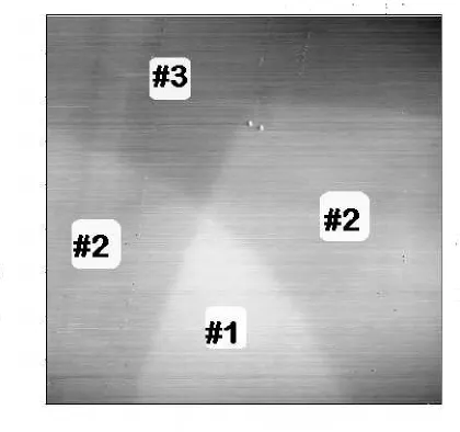
The rst image (Fig. 1) shows a 0:9m 0:9m area of the HOPG-surface, taken with a tunnel current of IT = 0.1 nA and a bias voltage of VBias =
100 mV. Three areas of distinct height dierence become visible: area # 1, of wedge like shape is the brightest, ie highest to the left and right one can see area # 2 and the dark top part corresponds to area # 3. The three areas are separated by average heights of s 3.2{3.3 A. This indicates that the steps
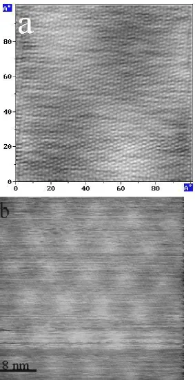
are of monatomic heights (s = 3.35 A), but they are not atomically sharp. The reason for that will be discussed later. Figs. 2a and 2b (4000 A 4000 A) are taken at around the same region as Fig. 1. For Fig. 2a a tunnel current of
IT = 0.1 nA was used, for Fig. 2b it was set to IT = 2 nA and the dierence
in the two images is striking. With a low current the surface topography only is observed. With a higher one additional features become visible. They are of centered hexagonal symmetry and propagate over the terraces without any change. Clearly these superperiodic features can not be explained by a rotation of the topmost layer, as this would result in a limitation of the superperiodic structure to one of the terraces only. Even a tip change in the lower third of Fig. 2b does not inuence the quality of this observation. The periodicity of the structures can clearly be seen in Fig. 3b and was determined to be S
82 A with a rotation of 30
with respect to the atomic lattice. The SPS
has an amplitude of z = 0:850:15 A. A closer zoom{in (Fig. 3a) reveals
that these features, visible as three brighter areas, are superimposed on the hexagonal atomic graphite lattice, which is generated by the b-sites of the
AB-stacked graphite lattice. The atomic graphite lattice has a corrugation of z 1.2 A and does not change in any regions of this image.
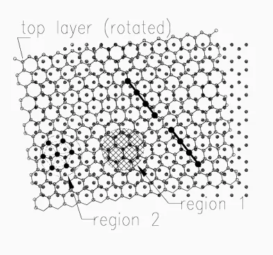
What kind of image can be expected if we assume a rotation of the top-most graphite layer with respect to the one underneath? Fig. 4 shows two graphite layers rotated with repect to one another. This changes the stacking sequence and therefore modies locally the density of states. Basically, two dierent phases of the atomic lattice can be dened. In some regions, noted 1, the honeycombs of both layers are on top of each other, giving rise to an
AA-stacking sequence there, whereas in other regions, noted 2, the usualAB -stack is maintained. Here the usual atomic graphite lattice, as imaged using STM, is highlighted as a centered hexagon. In type 1 regions the STM images will exhibit a much smaller corrugation since all carbon atoms are in a-site positions, which would distort the atomic lattice. Also, for type 2 regions with higher corrugation an `odd{even' transition along the atomic rows appears, as demonstrated by Saadaoui et al 19] and Nysten et al 20]. This yields a wavy
appearance of the atomic rows. This eect is demonstrated in the schematics (Fig. 4) by the shift of the two thick rows with respect to one another. There-fore, in general, a moire pattern which is superimposed on the atomic graphite lattice can not be due to a misorientation of thesingletopmost layer. At least two layers inAB-stacking sequence are required on the surface to get an STM image of the hexagonal graphite lattice withd= 2:46 A.
Recent numerical calculations on the appearance of moire patterns in STM by Kobayashi 16] have shown that nanoscale waves propagate through many layers without decay. This report asserts that these nanoscale features can be imaged with STM and appear superimposed on atomic scale structures. The appearance of these subsurface features in the image was calculated to become more distinct with increasing tip-sample distance, assuming a d-wave tip. Another interesting result of these calculations is that the amplitude or corrugation of the superstructure oscillates with the number of overlayers. For layered materials like graphite this amplitude does not decay with the over-layer thickness 16].
Experimental evidence of STM's capability to image features which originate well under the surface has been given by Parkinson et al 15] for epitaxially grown lms of transition metal dichalcogenides. Nanoscale moire patterns, due to a lattice mismatch between substrate and lm, are reported to propagate through a 10-layer thick epilayer.
How do these ndings compare to the presented data? The images shown here reveal that the appearance of the superperiodic structures in the images is very much dependent on the tip-sample distance. The features are observed with high tunnel currents of 2 nA but not with 0.1 nA. Kobayashi predicts just the opposite behaviour for the case of a metal (copper) sample and a d-wave tip. We do not know much about the properties of the Pt/Ir-tip and graphite is a layered material, which has a few states only at the Fermi energy. But this indicates that the variation of the electron density of states associated with the nanoscale features decays much faster in the direction from the surface to the vacuum than the variation of the density associated with the atomic periodicity.
No oscillatory behaviour of the SPS was found on the dierent terraces in the presented data. Therefore it is reasonable to assume that the thickness of the overlayer which is covering the defect is constant. The other interesting observation is that the SPS appears superimposed on the atomic graphite lat-tice. No `odd{even' transition along the lattice with the periodicity of the SPS occurs, associated with a wavy appearance of the rows of carbon atoms, like suggested by Saadaoui et al 19] for the case of a single top layer rotation and demonstrated by Nysten et al 20]. In fact, this wavy behaviour of the atomic rows can also be seen in other publications, like Rong et al 6] and Xhie et al 11]. This strongly indicates that in these cases a rotation of the top layer with respect to the underlying crystal is a valid explanation. In the results presented here no wavy pattern is observed on the atomic resolution images, the atomic graphite lattice is maintained in all areas without these `odd{even'
transitions. Taking this into account we come to the conclusion that a num-ber n of layers with n 2 covers the three terraces which are separated by
monatomic steps since the atomic graphite lattice is observed without `odd{ even' transitions of the atomic rows. We further suggest that this overlayer is rotated by an angle with respect to the underlying bulk, resulting in a tunnel{ current{dependent appearance of a superperiodic structure superimposed on the graphite lattice. The smoothness of the steps separating the terraces is not surprising in this model. The overlayer rolls over the steps in a carpet{like fashion which smears out sharp features. Therefore atomic steps buried under this carpet do not appear sharp anymore.
There are some possibilities as to how a rotation of several graphite layers can be induced, of which we are not able to favour any. It has been shown by other groups that this can happen during the process of cleaving with adhesive tape and successive folding back of layers 21,22]. A defect in the stacking sequence can also be introduced during the graphitization of the sample and therefore be an intrinsic property, as reported by Saadaoui et al 19].
Summary
To conclude, we have shown for this particular case and in general that moire patterns which appear superimposed on the usual atomic graphite lattice are not caused by a rotation of the single topmost layer. A superperiodic struc-ture superimposed on the atomic graphite lattice and propagating over at least three terraces of monatomic height has been observed. Its appearance is clearly tip{sample distance dependent, similar to calculations by Kobayashi 16], which indicates that STM is capable of imaging defects in the stacking sequence of the HOPG crystallite from several layers (n 2) under the
sur-face. This nding is highly relevant for the interpretation of STM studies of layered structures.
Acknowledgement
We would like to thank Aidan Quinn for his help and many stimulating dis-cussions and David Grouse and Cyriaque Kempf for their technical support. Financial support from the Irish Science and Technology Agency Forbairt (grant SC /97/ 729) is gratefully acknowledged.
References
1] D. Tomanek and S. G. Louie, Phys. Rev. B 37(14): 8327{8336, 1988. 2] H. A. Mizes and J. S. Foster, Science, 244: 559{562, 1989.
3] F. J. Cadete Santos Aires, P. Sautet, J. L. Rousset, G. Fuchs and P. Melinon, J. Vac. Sci. Technol. B12(3): 1776{1779, 1994.
4] J. Xhie, K. Sattler, U. Muller, N. Verkateswaran and G. Rhaina, J. Vac. Sci. Technol. B9(2): 833{836, 1991.
5] T. R. Albrecht, H. A. Mizes, J. Nogami, Sang il Park and C. F. Quate, Appl. Phys. Lett.52(5): 362{364, 1988.
6] Z. Y. Rong and P. Kuiper, Phys. Rev. B 48(23): 17427{17431, 1993.
7] M. Kuwabara, D. R. Clarke and D. A. Smith, Appl. Phys. Lett. 56(24): 2396{ 2398, 1990.
8] P. I. Oden, T. Thundat, L. A. Nagahara, S. M. Lindsay, G. B. Adams and O. F. Stanley, Surf. Sci. Let. 254: L454{L459, 1991.
9] T. Hashizume, I. Kamiya, Y. Hasegawa, N. Sano, T. Sakurai and H. W. Pickering, Journal of Microscopy 152(2): 347{354, 1988.
10] X. Yang, Ch. Bromm, U. Geyer and G. von Minnigerode, Ann. Physik 1: 3{10, 1992.
11] J. Xhie, K. Sattler, M. Ge and N. Nenkateswaran, Phys. Rev. B 47(23): 15835{ 15841, 1993.
12] C. Y. Liu, H. C. and A. J. Bard, Langmuir 7: 1138{1142, 1991.
13] V. J. Cee, D. L. Patrick and T. P. Beebe Jr, Surf. Sci. 329: 141{148, 1995. 14] D. L. Patrick and T. P. Beebe Jr, Surf. Sci. Let. 297: L119{L121, 1993. 15] B. A. Parkinson, K. Ueno, F.S. Ohuchi and A. Koma, Appl. Phys. Lett. 58(5):
472, 1991.
16] Katsuyoshi Kobayashi, Phys. Rev. B 53(16): 11091{11099, 1996.
17] Atomgraph Corp., 222 Sherwood Ave., Farmingdale, NY 11735-1718 USA . 18] Aidan Quinn, PhD thesis 1996, Trinity College Dublin.
19] H. Saadaoui, J. C. Roux, S. Flandrois and B. Nysten, Carbon 31(3): 481{486, 1993.
20] B. Nysten, J. C. Roux, S. Flandrois, C. Daulan and H. Saadaoui, Phys. Rev. B48(17): 12527{12538, 1993.
21] H. Chang and A. J. Bard, Langmuir 7: 1143{1153, 1991.
22] M. Muller, H. Beyer and T. Schimmel, DPG-conference, Muenster (Germany), 1997.
Figure 1: STM image of the HOPG–surface (0.9µm×0.9µm), taken withIT= 0.1 nA,VBias
= 100 mV, showing three terraces numbered1,2and3which are separated by smooth steps of monatomic height.
Figure 2: (a)IT = 0.1 nA and an offset of x = -1000˚A with respect to Fig. 1, (b) the same area withIT= 2nA where additional superperiodic features become visible in the STM image. The features propagate over the three terraces, a tip change does not influence the appearance of the superperiodic structure
[image:8.612.157.449.76.648.2]Figure 3: STM-images showing the superperiodic features: (a) with high magnification (100˚A×100˚A) resolving the individual graphite atoms and the superperiodic structure
super-imposed (bright areas). Note that the atomic rows of the graphite lattice do not show any phase shifts or ‘odd–even’ transitions. The periodicity of the hexagonal SPS isS≈82 ˚A(b)
with an amplitude of ∆z= 0.85±0.15 ˚A. Both images are taken withIT = 2nA.
[image:9.612.136.419.77.628.2]Figure 4: Schematic representation of two graphite layers rotated with respect to one another, resulting in a moir´e pattern. Two regions are defined: region 1, where locally the stacking sequence isAA...which gives rise toa-site character and region 2 with the usualAB...stack and alternatinga-sites andb-sites producing the usual atomic graphite STM image. Between two adjacent regions of type 2 there is a shift of the atomic rows (‘odd–even’ transition) as indicated in the schematic.