Published by CFS Documentation cell
Division of Centre for Electronics Design and Technology of India A Scientific Society of Department of Electronics,
Govt. of India, New Delhi.
First Edition: 1999
TRADE MARKS: All brand name and product names mentioned in this book are trade marks or registered trade mark of their respective companies.
Every effort has been made to supply complete and accurate information. However, CEDTI assumes no responsibility for its use, nor for any infringement of the intellectual property rights of third parties which would result from such use.
No part of this publication may be stored in a retrieval system, transmitted or reproduced in any forms or by any means, electronic, photocopy, photograph, magnetic or otherwise, without written permission of CEDTI.
FOREWORD
The Information Technology and Telecom sectors have suddenly opened up avenues, which require a very large specially trained manpower. These sectors are highly dynamic and need training and re-training of manpower at a rapid rate. The growing gap of requirement of the industry and its fulfilment has created a challenging situation before manpower training institutes of the country. To meet this challenge most effectively, Centre for Electronics Design and Technology of India (CEDTI) has launched its nation-wide franchising scheme.
Centre for Electronics Design and Technology of India (CEDTI) is an Autonomous Scientific Society under the Govt. of India, Department of Electronics with its Headquarters at New Delhi. It operates seven centres located at Aurangabad, Calicut, Gorakhpur, Imphal, Mohali, Jammu and Tezpur. The scheme will be implemented and coordinated by these centres.
The scheme endeavours to promote high quality computer and information technology education in the country at an affordable cost while ensuring uniform standards in order to build a national resource of trained manpower. Low course fees will make this education available to people in relatively small, semi urban and rural areas. State-of-the-art training will be provided keeping in view the existing and emerging needs of the industrial and Govt. sectors. The examinations will be conducted by CEDTI and certificates will also be awarded by CEDTI. The scheme will be operated through all the seven centres of CEDTI.
The CEDTI functions under the overall control and guidance of the Governing Council with Secretary, Department of Electronics as its Chairman. The members of the council are drawn from scientific, government and industrial sectors. The Centres have separate executive committees headed by Director General, CEDTI. The members of these committees are from academic/professional institutes, state governments, industry and department of electronics.
CEDTI is a quality conscious organisation and has taken steps to formally get recognition of the quality and standards in various activities. CEDTI, Mohali was granted the prestigious ISO 9002 certificate in 1997. The other centres have taken steps to obtain the certification as early as possible. This quality consciousness will assist CEDTI in globalizing some of its activities. In keeping with its philosophy of ‘Quality in every Activity’, CEDTI will endeavour to impart state of the art – computer and IT training through its franchising scheme.
The thrust of the Software Courses is to train the students at various levels to carry out the Management Information System functions of a medium sized esTablishment, manufacture Software for domestic and export use, make multimedia presentations for management and effectively produce various manufacturing and architectural designs.
An Advisory Committee comprising eminent and expert personalities from the Information Technology field have been constituted to advise CEDTI on introduction of new courses and revising the syllabus of existing courses to meet the changing IT needs of the trade, industry and service sectors. The ultimate objective is to provide industry-specific quality education in modular form to supplement the formal education.
The study material has been prepared by the CEDTI, document centre. It is based on the vast and rich instructional experience of all the CEDTI centres. Any suggestions on the improvement of the study material will be most welcome.
HISTORY & OVERVIEW OF AutoCAD
CAD been known around 1964, however it wasn’t widely used until around 1982, when CAD system such as AutoCAD became available on microcomputer.
FEATURES OF CAD
(1) Ease of Use
1.It is a clean & comfortable approach to drawing.
2. CAD is a valuable tool because it makes the tedious and inevitable task of revising drawings more pleasant.
(2) CAD as an Editor
1. When you edit a drawing, you can “ cut and paste “ objects to other parts of the drawing or to an entirely different drawing.
2. When you use CAD for a drawing containing the same object in several places, you can draw the object once, then insert it wherever it is needed.
(3) Creating Visual Models
1. CAD can be used to create a visual model of an imagined object.
2. You can quickly see whether an idea will work by using CAD to construct a graphic model, then checking in detail the design’s critical elements. Exp.- gears & cams.
(4) Accuracy
CAD allows greater accuracy than drawing by hand. Rather than
Depending on a graphic scale and the clarity of your sight to determine dimensions, you can use CAD’s built-in measuring capabilities to check the dimensions of the drawings you create.
(5) Intelligence
Another CAD feature is the ability to attach information to an object or
An entire drawing. Such a piece of information is called an attribute, and the ability to attach attributes to a drawing is often referred to as intelligence. An attribute can be visible or invisible. It can be a part number attached to a gear, the no. of phone lines attached to a desk, etc. These attributes can be extracted and manipulated in a data-base-management or spreadsheet program.
(6) Customization
A customization feature enables you to automate repetitive tasks. Exp.
GETTING STARTED
As we know AutoCADR13 is a window based package, so to start AutoCAD you have to open Windows95 or higher version.
In Windows95, you have to click on the START button at the status bar and move on the Program and then AutoCAD13. The options available in AutoCAD13 are
AutoCAD13
AutoCAD Readme
Online Help
Quick Tour
What’s New
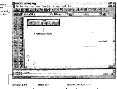
[image:6.612.95.480.290.584.2]Click on AutoCAD13 and soon you will get a screen as shown in fig.
Fig. Courtesy From Autodesk Release-14 Manual
At the bottom of the drawing area, the status bar gives you information at a glance about the drawing. The status bar gives you the information like coordinates, snap, ortho, model, tile & time.
In the lower-left corner of the drawing area, you see a thick, L-shaped arrow outline. This is the User Coordinate System (UCS) icon, which tells you your orientation in the drawing. This icon becomes helpful while drawing complex 2D & 3D drawings.
At the bottom of the screen, just above the status bar, is a small horizontal window, which is the command window.
Command: tells you that AutoCAD is waiting for your instructions.
At the top of the screen, the message written like AutoCAD UNNAMMED on blue line is known as title bar. Below that is the main menu bar, also known as Pull-Down Menus. The pull-down menus available on the menu bar offer an easy-to-understand way to access the general controls and settings for AutoCAD.
The pull-down menu options perform for basic functions:
Display additional menu choices
Display a dialog box that contains settings you can change Issue a command that requires keyboard or drawing input Offer an expanded set of the same tools found in the Draw
and Modify toolbars.
There is a second set of options and is called Cascading menu. Whenever you see a pull
down item with the triangular pointer, this item opens a cascading menu offering a more detailed set of options.
Flyouts:
Some tools will display a set of additional tools that are related to the too you have selected. This is shown in fig. This set of additional tools is called a toolbar flyout.
Fig. Courtesy From Autodesk Release-14 Manual
The various toolbars available in tools menu are: 1. draw
2. modify 3. dimension 4. solids 5. surfaces 6. preferences 7. render
8. external database 9. select objects 10. object snap 11. UCS
12. Object properties 13. Standard toolbar 14. Inquiry
15. Insert 16. Viewpoint 17. Zoom
There is a screen menu option from where various commands can be assessed. This screen menu will be displayed on the right side of your screen. You may or may not be seeing screen menu. If you are not, it can be displayed by going through the following steps.
1. Go to OPTIONS in main menu.
2. Select PREFERENCES. A dialog box will be seen on your screen. On AUTOCAD GRAPHICS WINDOWS click on the SCREEN MENU check button.
3. Then click OK.
HOW TO GIVE COMMANDS TO AutoCAD
There are three ways to give commands
1. Through TOOLBARS
2. Through SCREEN MENU
3. Through COMMAND: PROMPT
HOW TO DRAW A LINE ON SCREEN
To draw a LINE, you, first of all, understand the various COORDINATE SYSTEMS used to generate a line in AutoCAD.
(1) CARTESIAN COORDINATE
To specify a point a plane, we take two perpendicular lines. The horizontal line represents the X-axis and vertical line represents Y-axis. The meeting point of these lines is called as Origin. The X coordinate is positive if measured to the right of the origin & negative if measured to the left of the origin. The y coordinate is positive if measured above the origin & negative if measured below the origin as shown in fig . This method of specifying points in plane is called Cartesian coordinates.
AutoCAD uses following coordinate systems to locate a point in X-Y plane. a. Absolute coordinate system
b. Relative coordinate system c. Polar coordinate system
ABSOLUTE COORDINATE SYSTEM
RELATIVE COORDINATE SYSTEM
In relative coordinate system the displacement along X & Y axes are measured with reference to the previous point rather than the origin. The relative coordinate system is designated by the symbol @. Exp. = @4,0 here Distance in X-axis is 4 units & distance in Y-axes is 0. Now we will give another point @0,3 this displacement will be from point (4,0) and X=0 &Y=3 units.
POLAR COORDINATE SYSTEM
In the polar coordinate system a point can be located by defining the distance of the point from the current point, and the angle that the line between the two points makes with the positive X-axis. Exp. = @5<30. In this @5 gives the 5 units distance & <30 gives the angle or direction in which 5 units will be drawn.
Now we will draw a rectangle using all the three above-mentioned coordinate systems.
Type LINE at the command prompt & the computer will ask you FROM POINT: here you have to specify the point from where you have to start your line to make rectangle. Then computer asks you TO POINT: means the destination point. The computer continues to ask TO POINT: unless press enter or clicked right button of your mouse to terminate the command.
Command: line From point: 1,1 To point: 4,1 To point: 4,3 To point: 1,3
You will see a rectangle on your screen. This is drawn with the use of Absolute coordinate system.
Command: line From point: 1,1 To point: @4,0 To point: @0,3 To point: @-4,0 To point: @0,-3
Command: line From point: 1,1 To point: @4<0 To point: @3<90 To point: @4<180 To point: @3<270
This will draw a rectangle using Polar coordinate system.
The line command has three following options:
continue
close
undo
* Continue: - After exiting from the LINE command you may want to draw another line starting from the point where the previous line ended. In this case you may use Continue option. Perform the following steps.
Command: line From point: 2,2 To point: 6,2 To point: Enter
Command: line
From point: Either Enter here to continue or type @ to continue from point 6,2 To point: 6,5
To point: Enter
* Close: - The close option can be used to join the current point with the initial point of the first line when two or more lines are drawn in continuation. Type C at the last TO POINT: and see the result on your screen.
SAVING YOUR WORK
In AutoCAD you must save your work before you exit from the drawing editor or turn the system off. There are three options available in AutoCAD to save your work on Hard disk or on floppy diskette:
SAVE
SAVEAS
QSAVE
SAVE :- The SAVE command allows you to save your drawing by writing it to a permanent storage device, such as hard disk, or derive A or B.
Command: save
In the save dialog box as shown in fig., type the name in the FILE NAME edit box in which the drawing will be saved
SAVEAS :- The SAVEAS works in the same way as SAVE command.
You can choose the above options from the MAIN MENU. FILE--- SAVE or SAVEAS
QSAVE:- The QSAVE command saves the current named drawing without asking you to enter a filename, thus allowing you to do a quick save.
OPENING AN EXISTING FILE
FILE----OPEN
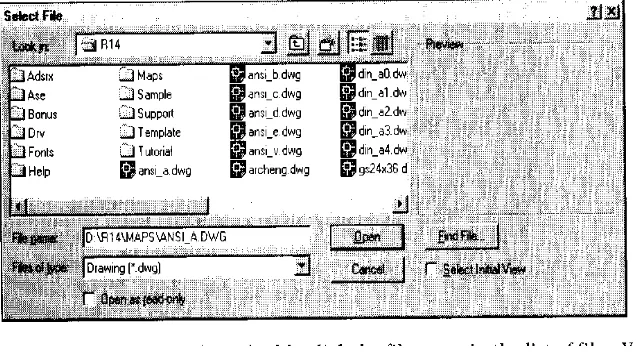
[image:13.612.166.484.216.394.2]To open an existing file either type OPEN at the command prompt or use MAIN MENU. The dialog box will be seen on your screen as shown in fig. You can either enter the name at the FILE NAME edit box or choose file name by using scroll bars. The individual files will be highlighted on by one.
Fig. Courtesy From Autodesk Release-14 Manual
STARTING A NEW FILE
FILE---NEW
When you are running an AutoCAD, you are already in drawing editor and the default name is UNNAMMED. The NEW command can be invoked from the Standard toolbar by selecting the NEW icon, the pull-down menu (select FILE, NEW…..), or the screen menu, or by entering NEW at the Command: prompt.
QUITTING A DRAWING
FILE---EXIT
You have successfully created your first drawing. Now we will move further towards other features of AutoCAD drawing various other important drawing functions. First we will learn how to draw a circle.
DRAWING A CIRCLE
DRAW---CIRCLE
Command: circle or C
The following is the prompt sequence for the CIRCLE command 3P/2P/TTR/<Center Point>:
1. Center & Radius Option
In this option you draw a circle by defining the center and the radius of the circle.
Command: C
3P/2P/TTR/<Center Point>: 3,2
Diameter/<Radius>: 1 (or @1<0, or @1,0)
2. Center & Diameter Option
In this option you can draw a circle by defining the center & diameter of the circle.
Command: C
3P/2P/TTR/<Center Point>: 4,2 Diameter/<Radius>: D
Diameter<current>: 3
3. Two-Point Option
You can draw a circle using the two-point option.
Command: C
3P/2P/TTR/<Center Point>: 2P First point on Diameter: 2,2 Second point on Diameter: 3,2
4. Three-point option
For drawing a circle, you can use the Three-point option by defining three points on the circumference of the circle.
Command: C
3P/2P/TTR/<Center Point>: 3P First point : 4,4
5. Tangent Tangent Radius option
A tangent is an object (line, circle, or arc) that contacts the circumference of a circle at only one point. In this option you specify two objects that are to be tangent to the circle, and the radius of the circle as shown in fig.
Command: C
3P/2P/TTR/<Center Point>: TTR
Enter Tangent Spec: select first line, circle, or arc
Enter second Tangent Spec: select second line, circle, or arc Radius<current>0.75
While editing you may find that at many times and at many places you want to erase lines or circles or you may observe + objects on your screen and you want to have a clear screen or want to see a part of your drawing in large, the following session will discuss the above mentioned topics.
ERASING OBJECTS
Modify --- Erase
To erase the object use ERASE command. You can invoke the ERASE command by entering Erase at the command prompt. A small box will be seen on your screen instead of the screen cursor. This box is known as PICK BOX. To erase an object move the pick box so that it touches the object.
Command: E
Select objects: select first object
CANCELLING A COMMAND
If you are in a command and you want to cancel or get out of that command, press the ECS (escape) key on the keyboard.
REDRAW COMMAND
This command redraws the screen, thereby removing the cross marks that appears when a point is picked on the screen. These marks are known as BLIPS.
Command: REDRAW or R
ZOOM COMMAND
Creating drawings on the screen would not be of much use if you could not get a magnified view of your drawing to work on minute details. You can zoom in and zoom out by using ZOOM command.
Command: ZOOM or Z
All/Center/Dynamic/Extents/Left/Previous/Vmax/Window/<scale(X/XP)>:
Window Option
It lets you specify the area you want to zoom in by letting you pick two opposite corners of a rectangular window.
Command: ZOOM or Z
All/Center/Dynamic/Extents/Left/Previous/Vmax/Window/<scale(X/XP)>: W First corner: pick first point
Second corner: pick second point.
Previous Option
When you have completed the editing you may want to return to the previous view. This can be done by using the PREVIOUS option of the zoom command.
Command: ZOOM or Z
All/Center/Dynamic/Extents/Left/Previous/Vmax/Window/<scale(X/XP)>: P
All Option
This option of the ZOOM command displays the drawing limits or extents, whichever is greater. Even if the objects are not within the limits, they are still included in the display. With the help of the ALL option, you can view the entire drawing in the current viewport .
Extents Option
HOW TO USE DRAW COMMANDS
So far we have use LINE & CIRCLE commands which comes under DRAW commands. In this session we will cover various other draw commands like ARC, ELLIPSE, POLYGON, POLYLINE,POINT &TEXT.
DRAWING ARC
Draw---ARC
An ARC can be drawn in 11 distinct ways using the options listed under the ARC command as shown in fig.
1. Three-point option:- The three points option requires the Start point, second point, & end point.
2. Start, Center, End option: - In this option, instead of entering the second point, you enter the center point of the arc.
3. Start, Center, and Angle option: - This option is best suited if you know the included angle of the arc. The INCLUDED ANGLE is the angle formed by the start point and the end point of the arc with the center.
4. Start, Center, Length of Chord option:- In this option you are required to specify the start point, center point, and length of the chord. A CHORD is defined as the straight line connecting the start point and the end point of an arc.
5. Start, End, Angle option:- You can draw an arc by specifying the start point of the arc, the end point, and the included angle.
6. Start, End, Starting Direction:- You can draw an arc by specifying the start point, end point, and the starting direction of the arc in degrees.
7. Start, End, Radius:-You can draw the arc by specifying the start point, end point, & the radius of the arc.
8. Center, Start, End option;- This is a modification of the start, center, end option. 9. Center, Start, Angle option:- This is a modification of the start, center, angle option
10. Center, Start, length of Cord option:- This is a modification of the start, center, length option
DRAWING RECTANGLES
Draw----Polygon (Rectangle)
Command: Rectangle
First corner: 4,3 ( lower left corner )
Other corner: 7,5 ( upper right corner location )
DRAWING ELLIPSES
Draw---Ellipses
Command: ellipse
Arc/Center/<Axis endpoint 1>: 5,4 (Exp. Of drawing an Ellipse using axis & Eccentricity option)
Axis endpoint 2: 8,3
<Other axis distance>/Rotation: 2
Drawing Ellipse Using the Center & Two Axes option
In this option you can construct an ellipse by specifying its center point, end point of one axis, and length of the other axis.
Command: ellipse
Arc/Center/<Axis endpoint 1>: C Center of ellipse: 5,4
Axis endpoint: 7,4
<Other axis distance>/Rotation: 2
Drawing Elliptical Arcs
AutoCAD will prompts you to enter information about the geometry of the ellipse and the arc limits. You can define the arc limits by using the following options:
1. Start & End angle of the arc; 2. Start and Included angle of the arc; 3. Specifying Start & End parameters.
DRAWING REGULAR POLYGONS
Draw----polygons
Command: Polygon Number of sides <4>: 8 Edge/<Center of polygon>: 4,4
Inscribed in circle/Circumscribed about circle (I/C) <I>: I Radius of circle: 1.5
DRAWING POLYLINES
Draw (POLYLINE)
A POLYLINE is defined as a line that can have different characteristics.
Command: PL
From Point: Pick the starting point or enter its coordinates. Current line width is 0.000
Arc/Close/Half width/Length/Undo/Width/<Endpoint of line>:
End Point of
Line:-This Option is maintained as the default, and is used to specify the end point of the current polyline segment.
Command: PL
From Point: Pick the starting point or enter its coordinates.
Current line width is 0.000
Arc/Close/Half width/Length/Undo/Width/<Endpoint of line>: Specify the end point of 1st polyline
Arc/Close/Half width/Length/Undo/Width/<Endpoint of line>: Specify the end point of 2st polyline
Width
Arc/Close/Half width/Length/Undo/Width/<Endpoint of line>: W Starting Width<0.0000>: specify the starting width (3).
Ending Width<starting width>: specify the ending width (0).
Close
This option closes the polyline by drawing a polyline segment from the most recent end point to the initial start point, and on doing so exits from the PLINE command.
Arc/Close/Half width/Length/Undo/Width/<Endpoint of line>: C
Halfwidth
With this option specify the starting & ending halfwidth of a polyline. This halfwidth distance is equal to half of the actual width of the polyline.
Arc/Close/Half width/Length/Undo/Width/<Endpoint of line>: H Starting halfwidth<0.0000>: specify the starting halfwidth. Ending halfwidth<starting width>: specify the ending halfwidth
Length
This option prompts you to enter the length of a new polyline segment. It will be drawn at the same angle as that polyline segment or tangent to the previous polyarc segment.
Arc/Close/Half width/Length/Undo/Width/<Endpoint of line>: L Length of line: specify the desired length of the Pline.
Undo
This option erase the most recently drawn polyline segment
Arc/Close/Half width/Length/Undo/Width/<Endpoint of line>: U
Arc
This option is used to switch from drawing polyline to drawing polyarc. Arc/Close/Half width/Length/Undo/Width/<Endpoint of line>: A
Angle/CEnter/Close/Direction/Halfwidth/Line/Radius/Second pt/Undo/Width/<Endpoint of arc>:
Angle: This option prompts you to enter the Included Angle for the arc.
Included angle: specify the included angle. Center/Radius/<Endpoint>:
Center: This option prompts you to specify the center of the arc to be drawn.
Angle/Length/<Endpoint>:
Angle refers to the included angle, Length refers the length of the chord, and Endpoint refers to the end point of the arc.
Close: This option closes the polyline by drawing a polyarc segment from the previous end point to the initial start point, and on doing so exits from the PLINE command.
Direction: The Direction option allows you to specify Tangent Direction of your choice for the arc segment to be drawn. The prompt will be:
Direction from start point:
End point: specify the end point of arc.
Halfwidth: This option is the same for the Line option and prompts you to specify the starting and ending halfwidth of the arc segment.
Line: This option takes you back to the Line Mode.
Radius: This option prompts you to specify the Radius of the arc segment. Radius: specify the radius of the arc segment.
Angle/<Endpoint>
Second pt: This option selects the second point of the arc in the three-point arc option. Second point: specify the second point on the arc.
End point: specify the third point on the arc.
Undo: This option reserves the changes made in the previously drawn segment.
Width: This option prompts you to enter the width of the arc segment. The prompt sequence is identical to that of the polyline.
DRAWING DOUGHNUTS
Draw---Circle (DONUT)
The DONUT command is issued to draw an object that looks like a filled circle ring called a doughnut.
Command: DONUT
DRAWING POINTS
The point is the basic drawing object. Command: POINT
Point: specify the location where you want to plot the point.
When a point is drawn a mark appears on the screen. This mark is known as a Blip.
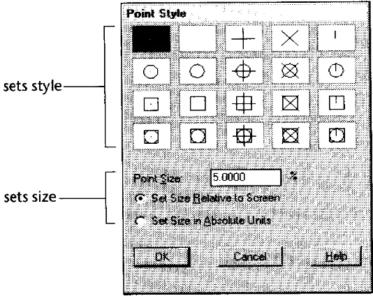
Changing the Point Type
Format---Point style
[image:23.612.145.412.284.496.2]The point style Dialog box will seen on the screen as shown in fig. You can select a point style in this box by clicking your pointing device on the point style of your choice. A box is formed around that particular point style to acknowledge the selection made. Next, click on the OK Button.
Exercise No.2-Draw the following drawing by giving the specifications as given
Drawing Limits: (1,1) & (10,7) Draw option used: Line, Circle
The various editing commands are: 1. Move
2. Copy 3. Offset 4. Rotate 5. Scale 6. Fillet 7. Chamfer 8. Trim 9. Extend 10. Stretch 11. Lengthen 12. Array 13. Mirror 14. Break
All these commands are available in single Toolbar known as MODIFY Toolbar.
MODIFY
1. Move:- Sometimes the objects may not be located where they should be. In such situation use the MOVE command.
Command: Move
Select objects: Choose objects individually or use the selection set. Base point or displacement: Specify any point on or near the object.
Second point of displacement: Select the new location by specifying a point on the screen.
2. Copy:- This command is used to copy an existing objects. This command is similar to the MOVE command in the sense that it makes copies of the object and places them at specified location, but the originals are left intact.
Command: Copy
Select objects: Choose objects to copy.
The option of the COPY command is used to make MULTIPLE copies of the same object.
Command: Copy
Select objects: Choose objects to copy. <Base point or displacement>/Multiple: M
Second point of displacement: Specify new location on the screen. Second point of displacement: Specify new location on the screen. Second point of displacement: Specify new location on the screen.
3. Offset:- If you want to draw parallel lines, polylines, concentric circles, arcs, curves, etc., use the OFFSET command as shown in fig.
Command: Offset
Offset distance or through<current>: Enter a value
Select object to offset: Pick the object offset. Side to offset? Specify the side for offsetting.
4. Rotate:- Sometimes when making drawings you may need to rotate an object or a group of objects. It can be accomplished by using ROTATE command.
Command: Rotate
Select objects: Choose objects to rotate.
Base point : Specify a base point on or near the object.
<Rotation angle>/Reference: Enter a positive or negative rotation angle, or pick a point.
5. Scale:- Many times you will need to change the size of a drawing and this can be done by the SCALE command. This command enlarges or shrinks the entire object or a part of it in the same ratio for the X & Y dimensions.
Command: Scale
Select objects: Choose objects to scale. Base point : Specify a base point on. <Scale factor>/Reference: Enter any value
6. Fillet:- This command is used to create smooth round arcs to connect two objects.
Command; Fillet
Polyline/Radius/Trim/<Select first object>:
7. Chamfer:- In drawing, chamfer is defined as the taper provided on a surface. Sometimes the chamfer is used to avoid a sharp corner.
Command: Chamfer
Polyline/Distance/Angle/Trim/method/<Select first object>:
8. Trim:- The TRIM command trims objects that extend beyond a required point of intersection. With this command you must select the cutting edge or boundary first. There can be more than one cutting edge. After the cutting edge or edges are selected you must select the object to be trimmed.
Command: Trim Select cutting edges: Select objects:
<select object to trim>/Project/Edge/Undo:
9. Extend:- This command may be considered the opposite of the TRIM command. In the EXTENT command you can lengthen or extend lines or arcs to meet other lines, arcs, polylines, circles, and rays.
Command: Extend Select boundary edges: Select objects:
10. Stretch:- The term stretching an object means changing only one of its dimensions; i.e., changing its length, width, or height .
Command: Stretch
11. Lengthen: -Like the TRIM & EXTEND commands, the LENGTHEN command can be used to extend or shorten lines. The LENGTHEN command has several options that allow you to change the length of objects by dynamically dragging the object end point, entering the delta value, entering percentage value, or entering total length of the object.
Command: Lengthen
Delta/Percent/Total/Dynamic/<Select object>:
12. Array: - In some drawings you may need to specify an object multiple times in rectangular or circular arrangement.
a. Rectangular array b. Polar array
a. Rectangular array: A rectangular array is formed by making copies of the selected objects along the X and Y-axes. The command allows you to choose the number of rows and columns. The rows & columns must be whole numbers as shown in fig.
Command: Array Select object:
Rectangular or Polar array(R/P)<current>: R Number of rows(---)<1>:
Number of columns(|||)<1>:
Unit cell or distance between rows(---): Distance between columns(|||):
b. Polar array: A polar array is an arrangement of objects around a point in a circular pattern as shown in fig.
Command: Array Select object:
Rectangular or Polar array(R/P)<current>: P Center point of array:
Number of items:
13. Mirror:- The MIRROR command creates a mirror copy of the selected objects; the objects can be mirrored at any angle. This command is helpful in drawing symmetrical figures.
Command: Mirror
Select objects: Pick the objects to be mirrored. First point of mirror line: Specify the first point. Second point: specify the second end point. Delete old objects?<N>: Enter Y for deletion.
14. Break:- This command cuts existing objects into two or erases portions of the object. a. 1 Point Option:- Using this option, you can break the object into two parts.
b. 1 Point Select Option: An object can be broken into two parts. c. 2 Point Option:- Object can be broken down into two selected points.
d. 2 Point Select Option:- This option is similar to 2 point option; the only difference is that instead of making the selection point as the first break point, you are allowed to pick a new first point.
Command: Break
DRAWING UNITS
Format ----UNITS
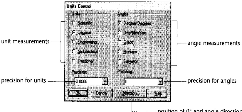
The UNITS command is used to choose a format for the units of distance and angle measurement. From the UNITS CONTROL dialogue box select a desired format of units or angles by selecting the button to the left of the item. The precision of units and angles can also be selected by selecting the arrow in the Precision as shown in fig.
Specifying Units Format 1. Scientific:- 1.75E+1,3.5E+1 2. Decimal:- 1.75,0.72
[image:31.612.95.507.333.524.2]3. Fractional:- 10-3/8,8-3/4 4. Engineering:- 0’10.375,0’8.75 5. Architectural:- 1’1-3/4”,3-1/4
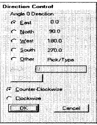
Fig. Courtesy from Autodesk Release-14 Manual Specifying Angle Format
1. Decimal Degrees:- 45.5
2. Degrees/minutes/seconds:- 90d30’45” 3. Grades:- 75g
4. Surveyor’s units:- N45d30’E
Grads are generally used in land surveying. There are 400 grads or 360 degrees in a circle. A 90-degree angle is equal to 100 grads.
Fig. Courtesy from Autodesk Release-14 Manual
DRAWING LIMITS
FORMAT----DRAWING LIMITS
The use of LIMITS command is to set up new limits. The default limits are 12.00,9.00 when AutoCAD is started. Limits are needed to size up a drawing area. The limits of the drawing are usually determined by the following factors:
1. The actual size of the drawing.
2. Space needed for putting down the dimensions, notes, bill of materials, etc. 3. Space between different views so that the drawing does not look cluttered. 4. Space for the border and a title block, if any.
Command: limits
ON/OFF/<Lower left corner><current>:0,0
Upper right corner<current>: 30,18 ( you can specify values according to your drawing)
Standard Sheet Sizes
Sheet sizes Metric system
Letter size Sheet size
A4 210 x 297
A3 297 x 420
A2 420 x 594
A1 595 x 841
A0 841 x 1189
LAYERS
Format---Layers
Object Properties----Layers
In manual drafting, different details of the drawing can be drawn on different sheets of paper, or overlays. In AutoCAD, instead of using overlays use layers. Each layer is assigned a name. Colour & linetype can also be assigned to these layers.
Advantages of Layers
1. Each layer can be assigned a different colour. 2. The layers are useful foe some editing operations.
3. Layer can be off or freeze that is not desirable in plotting.
4. Layer can be locked to prevent the user from accidentally editing the objects that layer. 5. The colour is also helpful in distinguishing different groups of objects.
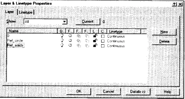
[image:33.612.116.489.431.630.2]The Layer Control Dialogue Box is seen on your screen as shown in fig.
Creating New Layers
The rectangular box just below the New, Current, Rename buttons is called the Layer edit box. Type the name of the layer, then pick the New button. The layer names will be displayed in the Layer Name list box.
Assigning a Linetype Or a Colour to a Layer
To assign a linetype or a colour to a layer, select the layer or layers that to assign a linetype or colour. Pick the SET LTYPE button from the dialogue box for selection.
To assign a colour, select the layer and then pick the SET COLOUR button from the dialogue box.
Controlling Display of Layers
Display of the layers can be controlled by selecting the layers and then picking the On, Off, Thaw, Freeze, Unlock, or Lock button.
With the ON and OFF option you can turn the layer on or off. The layers that are turned on are displayed on the screen and can be plotted. The layers that are turned off are not displayed on the screen and cannot be plotted.
While working on a drawing, if you do not want to see certain layers you can use the FREEZE option to freeze the layers. The frozen layers are invisible and cannot be plotted. The difference between the OFF and the FREEZE option is that the frozen layers are not calculated by computer while regenerating the drawing.
While working on a drawing, if you do not want to accidentally edit some objects on a particular layer but you still need to have them visible, you can use LOCK option to lock the layers.
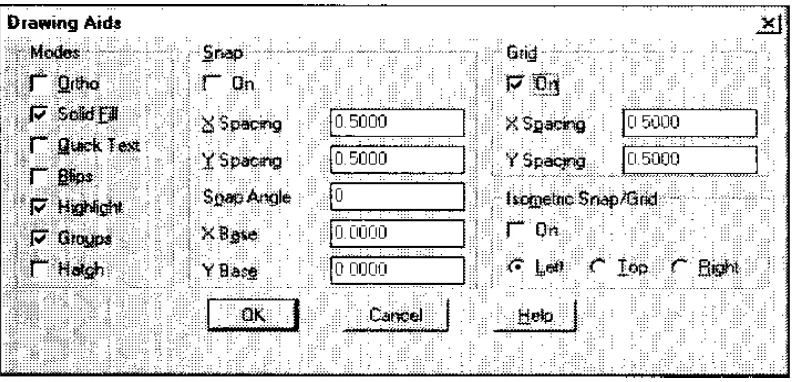
DRAWING AID DIALOGUE BOX
Tools---DRAWING AIDS
Fig. Courtesy from Autodesk Release-14 Manual
Grid Command
The GRID command can be used to display dotted lines on the screen at predefined spacing. These dotted lines act as a graph that can be used as reference lines in a drawing. Distance between the grid lines can be changed according to the requirements. The grids can be turned ON & OFF by pressing the F7 function key.
Snap Command
The snap is used to set increment for cursor movement. The SNAP command allows to set up an invisible grid that allows the cursor to move in fixed increments from one snap point to another. SNAP command can be turned ON & OFF by using the function key F9.
Ortho Command
Exercise No.5- Draw the following drawing using layers & limits.
OBJECT SNAPS
TOOLS---OBJECT SNAP
Object Snap is one of the most powerful features of AutoCAD. It improves performance & accuracy of drawing and make drafting much simpler than it normally would.
These snaps can be selected from the Object Snap toolbar, from the Standard Toolbar by selecting the desired icon from the Object Snap flyout.
[image:37.612.122.533.241.337.2]The following are the object snap modes available in AutoCAD:
Fig. Courtesy from Autodesk Release-14 Manual
NEArest:- The NEArest object snap mode selects a point on an object ( line, arc, circle) that is visually closet to the graphics cursor.
Command: line From point: NEA
to select a point near an existing object. To point: Enter
ENDpoint:- The ENDpoint object snap mode snaps to the closest end point of a line or an arc.
MIDpoint:- The MIDpoint object snap mode snaps to the midpoint of a line or an arc.
TANgent:- The TANgent object snap allows you to draw a tangent to or from an existing circle or arc.
CENter:- The CENter object snap mode allows you to snap to the center point of an arc or circle.
INTersect:- The INTersection object snap mode is used if you need to snap to a point where two or more lines or arcs intersect
PERpendicular:- The PERpendicular object snap mode is used to draw a perpendicular on a line. When you use this mode and select an object, AutoCAD calculates the point on the selected object so that the previously selected point is perpendicular to the line.
QUIck:- IF you are using an object snap when several objects cross the target box, AutoCAD normally searches all objects for the specified object snap mode and select the closest point. Depending on the hardware setup, this will cause delay in searching the specified point. The QUIck option stops searching as soon as AutoCAD finds a point on the object with the specified object snap.
NODe:- The NODe object snap can be used to snap to a point object. Command: line
From point: NOD Of select point P1 To point: NOD Of select point P2 To point: NOD Of select point P3
INSert:- The INSert object snap mode is used to snap to the insertion point of a text, shape, block, attribute, or attribute definition.
NONE:- The NONE object snap mode turns off any object snap and returns to the normal command prompt.
Command: line From point: MID To NONE Invalid point. From point:
APParent Intersection:- The APParent Intersection object snap mode is similar to the INTersection snap mode, except that this mode selects the visual intersection. The visual
GIVING TEXT TO YOUR DRAWING
DRAW---TEXT
The TEXT command lets you writ text on a drawing. AutoCAD provides a number of different character patterns, known as FONTS.
Text Alignment
[image:39.612.116.523.227.358.2]Alignment refers to the layout of the text. The main text alignment modes are left, center, & right.
Fig. Courtesy from Autodesk Release-14 Manual
Command: Text
Justify/Style/<Start point>:
Start point option:- By specifying a start point, the text is left-justified along its baseline starting from the location of the starting point. AutoCAD must know the text height, the rotation angle for the baseline, and the text string to be drawn.
Height<default>: Rotation angle:
Text: Enter a text string
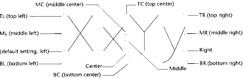
Justify option:- When the Justify option is invoked, the user can place text in one of the 14 various alignment types by selecting the desired alignment option as shown in fig..
Command: text
Justify/Style/<Start point>: J
Align/Fit/Center/Middle/Right/TL/TC/TR/ML/MC/MR/BL/BC/BR: select any of these
option.
Align: The text string is written between two points.
Center: You can use this option to select the midpoint of the baseline for the text.
Middle: Using this option you can enter a text not only horizontally, as in the previous case, but also vertically.
Right: This option is similar to the start point option. The only difference is that the text string is aligned with the lower right-corner i.e. the text is right justified.
TL option: In this option the text string is justified from the Top left.
TC option: Justify the text at the Top Center.
TR option: Justify the text at the Top Right.
Style option
With this option you can load another text style from already existing ones. Different text styles have different text fonts, height, obliquing angles, and other features.
Command: text
Justify/Style/<Start point>: S Style name ( or ? ) <current>:
If you want to activate another text style, enter the name of the style at the last prompt. You can also choose from a list of variable text style, which can be displayed by entering ?. Next prompt will be
Text style(s) to list <*>:
Press the enter key to display the available text styles.
Dtext Command
Dtext stands for dynamic text. This command performs all the functions that the TEXT command does, and in addition, you can see the text on the screen as you type it. It also lets you enter multiple lines in one command.
Drawing Special Characters
In all drafting applications, special symbols or characters are required like DEGREE symbol or the DIAMETER symbol. For each symbol the control sequence starts with a percent sign written twice (%%). The control sequences for some of the symbols are:
Control sequence Special character
%%c Diameter symbol ( )
%%d Degree symbol ( )
%%p Plus/minus tolerance symbol ( )
%%o Toggle for overscore mode on/off ( )
%%u Toggle for underscore mode on/off ( )
DIMENSIONING TECHNIQUES
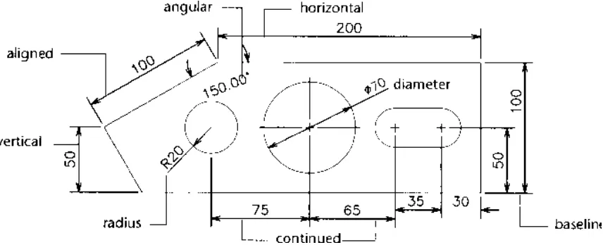
To make design more informative and practical, the drawing must convey more than just the graphic picture of the product. To manufacture an object, the drawing must contain size descriptions such as the length, width, height, angle, radius, diameter, and location of features. All this information is added to the drawing with the help of dimensioning.
FUNDAMENTAL DIMENSIONING TERMS
[image:41.612.95.523.272.446.2] [image:41.612.125.387.540.655.2]It is important to know and understand various dimensioning terms that are common to linear, angular, radial, diameter, and ordinate dimensioning as shown in fig.
Fig. Courtesy from Autodesk Release-14 Manual
Dimension Line
The dimension line indicates which distance or Angle is being measured.
Dimension Text
Dimension Text is a text string that reflects the actual measurement between selected points as calculated by AutoCAD.
Arrows
An arrow is a symbol used at the end of a dimension line. Arrows are also called terminator because they signify the end of the dimension line.
Extension line
Extension lines are drawn from the object measured to the dimension line. These lines are also called witness line.
Leader
A leader is a line that stretches from the dimension text to the object being dimensioned.
Sometimes the text for dimensioning and other annotations do not adjust properly near the object. In such cases use a leader and place the text at the end of the leader line.
Center Mark & Center Lines
The center mark is defined as a cross mark that identifies the center point of a circle or an arc. Center lines are mutually perpendicular lines passing through the center of the circle/arc and intersecting the circumference of the circle/arc.
Alternate units
With the help of alternate units you can generate dimensions for two systems of measurement at the same time. For exp., if the dimensions are in inches, you can use the alternate units
dimensioning facility to append metric dimensions to the dimensions.
Tolerances
Tolerance is defined as the amount by which the actual dimension can vary. AutoCAD can attach the plus/minus tolerances to the dimension text. This is also known as variance-style tolerance.
You can give tolerance symbols, material condition, tolerance value, datum value. In material condition the symbol (M) stands for Maximum Material Condition, (L) stands for Least Material Condition & (S) stands for Regardless of Feature Size.
Datum is a reference points, axis, or plane to make measurements and to verify dimensions.
Limits
Instead of appending the tolerances to the dimension text, you can apply the tolerance to the measurement itself. AutoCAD will automatically calculate the upper and lower limits of the dimension.
Associative Dimensions
Associative dimensioning is defined as a method of dimensioning in which the dimension is associated with the object that is dimensioned. The dimension is influenced by the changes in the size of the object. If the associative dimension is disabled, the dimension lines, arrows, leaders, extension lines, and the dimension text are drawn as separate objects. You can edit the dimension lines, extension lines, text, arrowheads as individual objects.
Linear Dimensioning
Linear dimensioning applies to those dimensioning commands that measure the distance between two points. The points can be any two points in the space, the end points of an arc or line, or any set of points that can be identified. Linear dimensions include Horizontal & Vertical
dimensioning.
Aligned Dimensioning
If an object is inclined at an angle, not parallel to the X axis or Y axis, in such situation use aligned dimensioning. You can measure true distance between the two points as shown in fig.
Baseline Dimensioning
Sometimes in manufacturing you may want to locate different points and features of a part with reference to a fixed point. This can be accomplished by using Baseline dimensioning. With this command you can continue a linear dimension from the first extension line origin of the first dimension. There must already be a linear, ordinate, or angular associative dimension to use the
Baseline or Continue dimensions.
Continue Dimensioning
[image:43.612.106.351.375.539.2]With the continue command you can continue a linear dimension from the second extension line of the previous dimension. This is also referred to as chained incremental dimensioning. The Continue & Baseline commands are used in a similar manner as shown in fig.
Fig. Courtesy from Autodesk Release-14 Manual
Angular Dimensioning
Angular dimensioning is used when you want to dimension an angle. This command generates a dimension arc to indicate the angle between two non-parallel lines .
Radial Dimensioning
Diameter dimensioning is used to dimension a circle, it can also be used to dimension an arc .
Generating Center Marks And Center Lines
When circles or arcs are dimensioned with the Radius or Diameter command, a small mark may be drawn in the center of the circle/arc. This mark is known as the center mark. This can be achieved by selecting the center mark icon from dimensioning toolbar.
Ordinate Dimensioning
Ordinate dimensioning is also known as arrowless dimensioning because no arrowheads are drawn in this type of dimensioning. Ordinate dimensioning is also known as Datum dimensioning because all dimensions are related to a common base point. The current UCS origin becomes the reference or the base point for Ordinate dimensioning. With ordinate dimensioning you can determine the X or Y displacement of a selected point from the current UCS origin.
[image:44.612.183.443.321.530.2]In Ordinate dimensioning, AutoCAD automatically places the dimension text ( X or Y coordinate value ) and the leader line along the X or Y axis. Since the ordinate dimensioning pertains to either the X coordinate or the Y coordinate, you should keep ORTHO on. When ORTHO is off, the leader line is automatically given bend when you pick the second leader line point that is offset from the first point as shown in fig.
Fig. Courtesy from Autodesk Release-14 Manual
The leader line for an X coordinate value will be drawn perpendicular to the X
axis and the leader line for a Y coordinate value will be drawn perpendicular to the Y axis.
Leader
The LEADER command draws a line that extends from the object being dimensioned to the dimension text. The leader line is used to attach annotations to an object or when the user wants to show a dimension without using another dimensioning command .
Changing Dimension Settings
The GEOMETRY dialogue box is shown in fig. We will each part of it brief.
Fig. Courtesy from Autodesk Release-14 Manual
Dimension Line
Suppress:- The suppress check boxes control the drawing of the first and second dimension line. By default both dimension lines will be drawn. You can suppress one or both dimension lines by selecting their corresponding check boxes.
Extension:- The EXTENSION edit box is used to specify the distance by which the dimension line will extend beyond the extension line. The Extension edit box can be used only when you have selected the oblique arrowhead in the Arrowhead pop-up list.
Spacing:- The Spacing ( Baseline Increment ) edit box is used to control the dimension line increment ( gap between successive dimension lines ) for the continuation of a linear dimension drawn with the BASELINE command.
Extension Line
Suppress:- You can suppress one or both extension lines by selecting the corresponding check boxes.
Extension:- Extension is the distance the extension line should extend past the dimension line. You can change the extension line offset by entering the desired distance value in the Extension edit box.
Arrowheads
1st: and 2nd: pop-up boxes:- AutoCAD has provided seven standard termination
[image:46.612.101.447.181.361.2]( arrowheads ) symbols that you can apply at each end of the dimension line. In addition to these, you can create your own arrows at each end of the dimension line. If you select first arrowhead it is automatically applied to the second by default.
Fig. Courtesy from Autodesk Release-14 Manual
Scale
Overall scale:- The current general scaling factor that pertains to all of the size-related dimension variable, like text size, center mark size, arrow size etc., is displayed in the Overall Scale edit box. You can alter the scaling factor of your requirement by entering the scaling factor of your choice in this box.
Center
There are three options in center 1. Mark:- if you want to have + mark on your circle or arc. 2. Line:- If you want to draw center lines for a circle or arc, pick LINE button.
3. None:- If you select none button, the center marks are not drawn.
Controlling Dimension Format
Fig. Courtesy from Autodesk Release-14 Manual
User Defined:- AutoCAD places the dimension text in the middle of the dimension line. By picking the User Defined, the dimension text can be place anywhere along the dimension line.
Force Lines Inside:- If the dimension text and the dimension lines are outside the extension lines and you want the dimension lines to be placed between the extension lines, Pick the Force Lines Inside check box.
Fit:- In the pop-up list, AutoCAD displays the available options for fitting the arrows and dimension text between the extension lines. The Fit options are:
1. Text and Arrows:- AutoCAD will place the arrow and dimension text between the extension lines if there is enough space available to fit both. 2. Text Only:- If space is not available for both arrows and text, the text is
placed inside the extension lines and the arrows are placed outside the extension lines.
3. Arrows Only:- AutoCAD will place the arrow and dimension text between the extension lines if there is enough space available to fit both. If there is enough space to fit the arrows, the arrows will be placed inside the extension lines and the dimension text outside the extension lines.
4. Best Fit:- This is the default option. In this AutoCAD places the dimension where it fits best between the extension lines.
5. Leader:- AutoCAD creates leader lines if there is not enough space available to fit the dimension text between the extension lines. The horizontal justification determines whether the text is placed to the right or the left of the leader.
Horizontal Justification
Options Description
Centered Places text between extension lines 1st extension line Places text next to first extension line 2nd extension line Places text next to second extension line
Over 1st extension Places text aligned with and above the 1st extension line Over 2nd extension Places text aligned with and above the 2nd extension line
Text
Use Text option to specify the alignment of the dimension text with the dimension line. These options can be used to control alignment of the dimension text for linear, radius, and diameter dimensions.
Inside Horizontal:- If you turn this check box off, the dimension text is aligned with the dimension line only when the dimension text is between the extension line.
Outside Horizontal:- If you turn this check box off, the dimension text is aligned with the dimension line only when the dimension text is outside the extension lines.
Vertical Justification
The Vertical pop-up list controls the vertical placement of the dimension text. The current setting will be highlighted.
Centered:- The dimension text gets centered on the dimension line in such a way that the dimension line is split to allow for placement of the text.
Above:- The dimension text is placed above the dimension line, except when the dimension line is not horizontal and the dimension text inside the extension lines is horizontal.
Outside:- This option places the dimension text on the side of the dimension line.
JIS: This option lets you place the dimension text to conform to JIS representation.
Annotation Dialogue Box
Use the Annotation dialogue box to control the dimension text format as shown in fig. AutoCAD lets you attach a user-defined prefix or suffix to the dimension text.
Primary Units
Fig. Courtesy from Autodesk Release-14 Manual
Zero Suppression
If you want to suppress the leading Zeros in all of the distance measured in decimals, check the Leading check box. For exp., by picking this box, 0.0750 becomes .0750. If you want to suppress the trailing zeros in all the distances measured in decimals, check the Trailing check box. As in the above exp., 0.0750 becomes 0.075.
Tolerance
The Tolerance area of the Annotation dialogue box lets you specify the tolerance method, tolerance value, justification of tolerance text, and the height of the tolerance text.
Method:- This allows you to select the tolerance method. The tolerance methods supported by AutoCAD are Symmetrical, Limits, Deviation, and Basic
Symmetrical:- In this the value specified in the Upper Value edit box is applied to both plus and minus tolerance. For exp., if the value specified in the upper value edit box is 0.005, the tolerance appended to the dimension is 0.005.
Deviation:- The value in the Upper Value and Lower Value edit boxes will be displayed as plus and minus dimension tolerance. For exp., if the upper value of the tolerance is 0.005 and the lower value of the tolerance is 0.002, the resulting dimension text generated will have a positive tolerance of 0.005 and a negative tolerance of 0.002.
Basic:- a basic dimension text is dimension text with a box drawn around it. Reference dimensions are used primarily in geometric dimensioning and tolerances. The basic dimension can be realized by picking the basic tolerance method. The Basic dimension is also called a Reference dimension.
Justification:- Justification lets you justify the dimension tolerance text. Three justifications are possible Bottom, Middle, and Top.
Text
Exercise No.8 Draw the following drawing and use proper dimensioning.
HATCHING
In many drawings, the area must be filled with some pattern. Different filling patterns make it possible to distinguish between parts or components of an object. Also, the material the object is made of can be indicated by the filling pattern. Filling the objects with a pattern is known as hatching.
The BHATCH Command
The BHATCH or the boundary hatch command allows you to hatch a region enclosed within a boundary by picking a point inside the boundary or by selecting the object to be hatched. This command automatically designates a boundary and ignores any other objects that may not be a part of this boundary. The Boundary Hatch box can be called out from the DRAW Toolbar.
Boundary Hatch Options
The Boundary Hatch dialogue box has several options that let you control various aspects of hatching, like pattern type, scale, boundary parameters, and associatively.
Pattern Type
This area lets you choose the type of hatch pattern you want. The default hatch pattern is predefined. AutoCAD displays a list of the available options, like User-defined, custom, and Predefined.
User-Defined Hatch Pattern
If you want to define a simple pattern, you can pick the User-Defined pattern in the pattern type list box. The boxes: the Spacing and the Double Hatch Check box will be enabled.
Custom Pattern
The second way to select a predefined hatch pattern is by selecting the custom pattern type, then entering the name of the stored hatch pattern in the Custom Pattern edit box. The custom pattern type can be selected by choosing the down arrow in the Pattern Type list box. You can do this if you know the name of the hatch pattern. For exp., you can enter Plastic or Steel as a hatch pattern. In AutoCAD all hatch patterns are stored in the file named ACAD.PAT. If AutoCAD doesn’t locate the entered pattern in the ACAD.PAT file, it searches for it in a file with the same name as the pattern.
Boundary Area
Pick Points<
This option makes AutoCAD automatically construct a boundary. To select this option, choose the Pick Points< button in the Boundary Hatch Dialogue box. The following prompts appears:
Select internal point: Pick a point inside the object. Selecting everything…
Selecting everything visible… Analyzing the selected data.
Select internal point: Pick a point or press the Enter key to end selection. 1. Pick point by clicking Pick button
2. Pick point inside the object (Square in this case)
3. Pick another point inside the other object (Triangle in this case) 4. Then Apply.
Select objects<
This option in the Boundary Hatch Dialogue box lets you select objects that form the boundary for hatching. AutoCAD prompts you to select objects. This option can also be used after a boundary has been defined. This way you can select any object that may be present within the boundary so that it is no hatched .
Remove Islands
This option is used to remove any islands from the hatching area. For exp., if you have a rectangle and a circle and you use the Pick Points option to pick a point inside a rectangle, AutoCAD will select both circles and rectangle. To remove the circle you can use the Remove Islands option. When you select this option, AutoCAD will prompts you to select the islands to remove.
Inherit Properties<
If you want to have the same hatching pattern and style as that of an existing hatch on the screen, pick the Inherit Properties button. The dialogue box is cleared from the screen and the following prompts appear:
Select hatch object: select a hatch pattern. Select hatch object:
Advanced options
Defining a boundary by specifying an internal point is quite simple in the case of small and less-complicated drawings. It may take more time in the case of large, less-complicated drawings because AutoCAD examines everything that is visible in the current viewport, so the larger and more complicated the drawing, the more time it takes to locate the boundary edged. When you select the Advanced button the Advanced Option dialogue box is displayed on the screen.
Object Type
The Object Type option controls the type of object AutoCAD will create when you define a boundary. It has two options: Polyline and Region.
Define Boundary Set
The boundary set comprises the objects that the BHATCH command uses when constructing the boundary. A boundary can be produced faster by specifying a boundary set because in this case AutoCAD does not have to examine everything on the screen.
Make New Boundary Set
This option is used to create a new boundary set. All the dialogue boxes are cleared from the screen to allow selection of objects to be included in the new boundary set. While constructing the boundary set, AutoCAD uses only those objects that you select and are hatchable.
Style
The hatching style can be specified by selecting a style from the style list box as shown in fig.s. There are three styles from which you can choose: Normal, Outer, and Ignore.
Normal:- This style hatches inward starting at the area boundary, at each end of the hatch line. In this alternate areas of the selected object are hatched starting with the outermost area.
Outer:- This particular option also lets you hatch inward from an area boundary but the hatching is turned off if an internal intersection is encountered. The hatching process in this case starts from both ends of each hatch line, so only the outermost level of the structure is hatched, hence the name Outer.
Ignore:- In this option all areas bounded by the outermost boundary are hatched, ignoring any hatch boundaries that are within the outer boundary.
BLOCKS
Draw---Blocks
The ability to store parts of a drawing, or the entire drawing, so that they need not be redrawn when needed again in the same drawing or another drawing, is extremely beneficial to the user. These parts of a drawing, entire drawings, or symbols (also known as blocks) can be placed (inserted) in a drawing at the location of your choice, in the desired orientation, with the desired scale factor.
Converting the Objects into a Block (BLOCK command)
Draw---Block
You can use BLOCK command to save any object as a block.
Command: BLOCK
Block name(or ?): specify the block name. Insertion Base point: Pick a point.
Select objects: Select all the objects comprising the block.
Once you have selected the objects defining the block, AutoCAD acknowledges creation of the block by removing the objects defining the block from the screen. You can get back the objects at the same position by entering OOPS.
Within the BLOCK command, you can list all the blocks defined in that drawing.
Command: BLOCK Block name (or ?): ? Block(s) to list<*>:
The lists of blocks of that particular drawing will be seen on your screen.
Inserting Blocks
Insertion of a pre-defined block is possible with the INSERT command.
Command: INSERT
Block name (or ?): Enter the name of the block to be inserted.
Insertion Point: Pick the point where you want the insertion base point for the blocks X scale factor<1>/Corner/XYZ: Pick a point, enter a number, or press the Enter key Y scale factor (default = X): Pick a point, enter a number, or press the Enter key Rotation angle<0>: Pick a point or enter an angle.
Inserting Blocks Using the Insert Dialogue Box
[image:57.612.166.431.212.505.2]Another method of inserting blocks is by specifying the different parameters of the block to be inserted in the Insert dialogue box., which can be invoked from the Insert Block flyout in DRAW toolbar.
Fig. Courtesy From Autodesk Release-14 Manual
Block… edit
box:-This edit box is used to specify the name of the block to be inserted. Pick the block.. button to generate the Defined Blocks dialogue box. Pick the desired block to be inserted.
File… edit
Inserting Multiple Blocks (MINSERT command)
Insert--- Insert Multiple Blocks
The MINSERT command is used for multiple insertion of a block. This command comprises features of the INSERT and ARRAY commands.
Command: MINSERT
Block name (or ?): Enter block name. Insertion point: Specify the insertion point. X scale factor<1>/Corner/XYZ:
Y scale factor<default = X): Rotation angle<0>:
Number of rows(---)<1>: Number of columns(|||)<1>:
Unit cell distance between rows(---): Unit cell distance between columns(|||):
In the array of blocks generated with the use of MINSERT command you cannot alter the number of rows/columns or the spacing between them. The whole MINSERT pattern is considered one object that cannot be exploded.
Creating Write Blocks (WBLOCKS command)
Changing Properties Of An Object
Use CHPROP (change properties) command to change the properties of an object.
Command: CHPROP
Select objects: Pick the object whose property you want to change Select object:
Change what property (Color/LAyer/Ltype/ltScale/Thickness)? Specify property to be changed.
Color:- By picking this button, Select Color dialogue box is displayed on the screen. Select the new layer to assign to the selected object from the list of layers in this dialogue box.
Layer:- Picking this button displays the Select Layer dialogue box on the screen. Select new layer to assign to the selected object from the list of layers in this dialogue box and pick the OK button.
Linetype:- Picking the linetype button displays the Select Linetype dialogue box on the screen. Select the new linetype to assign to the selected object from the list of linetype in this dialogue box.
Linetype Scale:- Enter the new linetype scale factor of the selected object in the Linetype Scale…edit box.
Thickness:- Enter the new thickness of the selected object in the Thickness…edit box. Once you have made the changes, pick the OK button to change the selected objects.
Polyline Editing (Using The PEDIT command) Toolbar---Modify---Edit Polyline
A polyline can assume various characteristics such as width, linetype, joined polyline, closed polyline, etc. You can edit polylines, polygons, or rectangles to attain the desired characteristics using the PEDIT command.
Command: Pedit
Select polyline: Pick the polyline to be edited using any selection method
If the selected line is an arc or line (not a polyline), AutoCAD issues the following prompts:
Object selected is not a polyline.
Do you want it to turn into one? <Y>: Y
The next prompt displayed is:
Close/Join/Width/Edit vertex/Fit/Spline/Decurve/Ltype gen/Undo/eXit <X>:
Open:- If the selected polyline is closed, the Close option is replaced by the Open option. The Open option will work on a polyline in which the closing segment was created by the Close option.
Join:- This option appends lines, polylines or arcs that touch a selected polyline at any of its end points and adds them to