••• ••••
•
•••••
• ••
••
•
••• ••
•
••• ••••
•
•••••
•••
•
••
• • •
• • • •
•
•
• • • • • • •
•
• • • • •
•
•
• •
• • • • •
•
• • •
•
• • •
•
• •
• • •
•
•
•
•
•
•
• •
••••
••••
•• ••••• ••••
•••••• ••••••
•••••••••
••
••••
••
• ••••
••••••
•• • •••••
•••
••
•
•
••••• ••••• • ••
•
FOR: _ _ _ _ _ _ _ _ _ _ _ _ _
TYPETRONIC®, OPTIMATIC, PAGE GAGE,
MULTIMODE, VERSATRONIC,
COPYMATIC, PARAPROCESSING
and TYPETRONIC VERTIPUNCH
are Trademarks of the SCM CORPORATION
Preface
..
From a programming standpoint, the TYPETRONIC 7816 Automated Data Computing system is an
extension of the TYPETRONIC 2816 Automated Data system. The 7816 retains all of the highly versatile functional and programming characteristics of the 2816 and supplements them with computing and digital storage capability.
This manual has been prepared for those who have a working knowledge of TYPETRONIC 2816
programming and now wish to acquire basic 7816 programming technique. This manual is a primer only and should not be treated as a comprehensive textbook.
For those who have not yet become familiar with 2816 programming, it is recommended they acquire a copy of the 2816 POINT TO POINT
PROGRAMMING MANUAL (Form No. DPS 2016). Both the 2816 and 7816 POINT TO POINT PROGRAMMING MANUALS deal with
programming and procedural characteristics only. Complete functional and operating descriptions of the 2816 and 7816 systems will be found in their
associated PRODUCT DETAIL MANUALS
(Form Nos. DPS 2014 and 2015).
Primary 7816 application programming is a service provided at no charge to all
SCM TYPETRONIC customers by the SCM Data Processing Systems Division.
Contents
1. INTRODUCTION ... 2-4
2. 7816 CONTROL AND PROGRAMMING CODES.5-11
Processor Access Codes... .• . . . ... . . .. 6
Processor Instruction Codes ... 7
Typetronic 7816 Code Chart ... 9
Typetronic 7816 Registers ... 10
Register Schematic ... 11
3. COMPUTING CHARACTERiSTiCS ... 12-16 Arithmetic ...•...•... 12
Computational Speed ... 12
Application Speed vs. True Speed ... 13
Paraprocessing ...•... 13
Basic Processor Operation ... 14
Processor Entry (PAl) ... 14
Transfer (PA2) ... 15
Output with PA3 ... 15
Output with PA4 ...•... 16
Output with PA5 ... 16
PA6 Sequence ... 16
4. BASIC PROCESSING EXAMPLES ... 17-18 5. WRITING THE PROGRAM ... 19-25 The Typetronic Layout Sheet ... 19
The Processor Output Program Panel ... 21
The Typetronic Program Sheet ... 25
6. PROGRAMMING EXAMPLES ...•.•... 26-32 7. PHYSICAL PREPARATION OF PROGRAMS ... 33
8. PREPARING FIELD CONTROL TAPES ... 35-37 Field Control Media ... 35
Field Control Tracks ... 35
Set·Up ...•...•••.• 36
Conditioning ....•••...•...•... 36
1.
Introduction
How The 7816 Differs From The 2816
The TYPETRONIC 7816, is an extension
of the TYPETRONIC 2816 Automated
Data System. The most significant difference in the two systems is the inclusion of a "Computing Processor" with the 7816. The Processor consists of an electronic solid-state a'rithmetic unit connected to an SCM de-signed magnetic memory disc. The Processor, from a hardware viewpoint, is an independent
Manual Control
CLEAR STORAGE
Differences I n Control
Restore
This key, familiar as the PARITY Reset control of the 2816 system has two additional functions with the 7816.
1. When depressed during a manual entry it will clear the buffer
register, if track seven of Field Control is programmed to
permit this. It clears all register indications, decimal modifiers, sign reversals, and restores the original order entry.
2. When the RESTORE key is operated simultaneously with the CLEAR STORAGE key it clears all "unlocked" 7816 registers.
Clear Storage
The CLEAR STORAGE key, familiar to 2816 users as the 7-8 PUNCH control also has three functions. As with the 2816 system, this key, when held down while a typing key is oper-ated, will add the 7-8 bit holes to a code configuration. CLEAR STORAGE, when operated with the RESTORE key, will clear all registers not locked by Program Panel wiring. Finally, with Code Control "ON", this key operated with certain printing keys can be used to manually "address" the TYPETRONIC Computing Processor.
MULTI MODE
Field ControlUnlike the 2816, MULTIMODE Field Control is a standard feature on all 7816 systems. In addition to dual-mode control ability, as desc:!ribed in the 2816 PRODUCT DETAIL MAN-UAL, the 7816 Field Control provides two supplementary tracks (7 and 8) of control. These tracks are always"ON"during
a PAl external entry sequence (See Section 2, 7816 control
and programming codes).
MULTIMODE Field Control (continued)
Track Seven
This track is used to enable the clearance of a manual entry with the RESTORE
control key. If no signal is programmed in
this track, the clear-entry function will not occur (this does not affect the operation of the RESTORE key as a pal'ity reset or Clear Storage function when used with the CLEAR STORAGE key).
When track seven does provide a signal at a given column during a manual entry to the system, depression of the RESTORE key will clear the entry back to the order entry designation. A proper clearance is indicated by the light under the RESTORE key.
Track Eight
Typically track eight is used as a decimal verifica tion track. A signal from this track turns on Reader One to initiate the auto-matic printing of a decimal representative code. This track is active whenever a P Al (external entry) command code has been read (with Code Control "ON"). Since this track will always be on during a P Al sequence, it can be used as a "third" Reader One On mode during these sequences.
The 7816 system is also distinguished from the 2816 by an Output Control Panel. This panel is used fO'r the control of Processor output, and is quite easy to program. Control Panel programming information will be found in section 3.
Automatic Control
The 7816 is controlled automatically by "control codes" just as the 2816 system.
The technique used for controlling the operating and computing functions of the 7816 is called VERSATRONIC programming. This technique permits virtually absolute freedom in format design, systems operation, and control programming.
2.
7816 Control
and Programming
Codes
(A Complete TYPETRONIC Code Chart is on page 9.)
Because of the unique VERSATRONIC pro-gramming technique used with the 7816 sys-tem, form and field requirements are virtually "non-restrictive." This means that entries and read-outs can be made in any logical position on a form, with complete freedom of columnar selection. There are two general classes of Processor codes, Access and Instruction.
The Processor Access Codes (PA codes)
Six codes, not used in the 2816 system, initiate "access" to the Processor and condition it for specific types of entry or output. These codes function as control codes (as described in the 2816 programming manual) and their response is governed by the state of the Code Control mode. That is, if Code Control is on these codes will function but not punch, and if Code Control is off they will punch but not function. (NOTE: When these functions are initiated manually, rather than through an OPTIMATIC Reader, they will punch if a Vertipunch is on.)
The Six PA Codes Are:
PAl
I-I I · I I 1-1-1
PA2
I I-I · I I 1-1-1
PA3
1-1-1 · I-I
1-1-1
PA4
I I 1-· I I 1-'-(
PAS
I-I 1-· I-I 1-1-'
PA6
1-1-· I-I 1-1-1
Alerts the Processor for an external entry (an entry from keyboard or reader). Whenever the PAl code is read (with Code Control "ON") Field Control tracks 7 and 8 will be activated.
When the PAl code is read, a sequence of following Instruction codes will have specific meaning to the Processor (see Entry description on page 14.).
The PA2 code conditions the Processo'r for an Internal Transfer (a transfer from the buffer register to one or more of the storage or factor registers).
This code prepares the Processor for ou tpu t from any selected Processor stor-age register to any "ON" system components (printers & punches) and the buffer register. The selected register is always "clear" after a PA3 sequence.
The PA4 code is also an output command, but it establishes output from a register by use of the extractor function as programmed on the Output Program Panel. The "extractor" enables selected orders of a register to be read out to the buffer (and "ON" output components) as zeros. This feature provides an effective means of "discarding" unwanted digit remainders, and obtaining true register splits. The selected output register is clear after a P A4 sequence unless the program panel is wired to prevent this.
Also an output code, PA5. sets up selected register output (as with PA3) with an additional automatic transIer to the D (multiplicand) register. PA5 is used most frequently when a series of multiplications (such as chain discounts) are to be performed (i.e. transferring the Product to the Multiplicand 'register auto-matically). The selected register clears unless prevented by program panel wiring.
This is a "zero interrogation" access code. When this code is read (along with a selected register code), the register will be examined for ze'ro content. When the content is zero, a code signal will be emitted from the Processor. Since this signal can be Program Panel wired to be any (five-hole) TYPETRONIC code (other than PA codes), great versatility is possible. The PA6 sequence does
The PROCESS Code CHANNEL NUMBERS
~
I I 1-· 1-1-1-1-1
One additional Processor control code (PROCESS) is used with the 7816 system. The code is in effect the "go" code. After the appropriate P A code has been read along with the Instruction codes, the PROCESS (PRC) code in-itiates the action. It figuratively tells the Processor to "perform the functions" that have been indicated by the PA code sequence. The PRC code always ter-minates a PA sequence.
Processor Instruction Codes
The codes that instruct the Processor "how to do it" after the PA code has indicated "what to do" are called Instruction codes. They are grouped into six categories:
1. Register Selection Instruction
These codes, when read after a P A code, will instruct the Processor what register or registers
to operate on. With input and transfer (PAl and PA2), TYPETRONIC 7816 registers may
be selected individually or in groups. With Output (PA3, PA4, PA5,) and zero-test (PA6), only one register should be selected in the P A sequence.
The following TYPETRONIC I/O Printer codes are used to select registers. When read during any P A sequence (with Code Control "ON") these codes will not print or punch even though AUTO PRINT or VERTIPUNCHes are on:
I/O Printer Code
F G H I J K P A B D R
2. Entry "Shift" Codes
Instruction
Selects Register F for I nput, Transfer or Output Selects Register G for Input, Transfer or Output Selects Register H for I nput, Transfer or Output Selects Register I for Input, Transfer or Output Selects Register J for Input, Transfer or Output Selects Register K for I nput, Transfer or Output Selects Product Register for Input, Transfer or Output Selects Register J for Sign Reversal I nput Only
Selects Register K for Sign Reversal I nput Only Selects Multiplicand Register for Entry Only Selects Multiplier Register for Entry Only
These codes "left shift" the decimal point of an entry. They are used when percentages or
prices per hundred or thousand are used. When entered manually at automatically (in a PAl
sequence) they will print and punch (if AUTO PRINT and/or a VERTIPUNCH is on).
They are effective in a P A2 sequence but will not print or punch.
%
Shifts the decimal entry two places to the left C Shifts the decimal entry two places to the left M Shifts the decimal entry three places to the left3. "Sign" Reversal Codes (Negatives)
Sign reversal codes algebraically affect the sign of selected registers. Since the effect is alge-braic, two negatives will make a positive and the Non-printing Minus (N) combined with the Printing Minus (-) will be positive.
N Non-printing Minus. Will not print or punch in a PA sequence.
Printing Minus. Will print and punch. Used most frequently in a manual entry to reverse the sign of an entry from its norm. The Printing Minus is also effective in a PA2 sequence, but in this sequence it
will
not
print or punch.4. Order Entry Designations
The Order Entry codes are always read immediately following a PAl code and they must be so programmed. The ten decimal digits (0-9) and the letter "Y" are used to designate the start order of the first digit entry into the buffer. Subsequent digits enter sequentially into lesser order positions.
y
o
(zero)
9 8
7
6
5
4
3
2
1
Selects the eleventh order for entry to the D (multiplicand) and R (multiplier) registers only. Selects the tenth order of entry to all registers Selects the ninth order of entry to all registers Selects the eighth order of entry to all registers Selects the seventh order of entry to all registers Selects the sixth order of entry to all registers Selects the fifth order of entry to all registers Selects the fourth order of entry to all registers Selects the third order of entry to all registers Selects the second order of entry to all registers Selects the first order of entry to all registers
5. Register Split Selection (Output Only)
The alternate part of a register may be selected for output by including the digit 2 in the output (PA3, PA4, PA5 or PA6) sequence. When the digit 2 is used in this manner it will not print or punch.
6. The Space Code
During a PAl sequence the space code will be recognized as a zero in the Processor. On out-put (PA3, 4 or 5), zeros before the first significant digit will print and punch as spaces.
7. Backspace
TYPETRONIC 7816 Systems Code Chart
PRINTING CHARACTER CODES SYSTEM CONTROL CODES
7816 PROCESSOR ACCESS CODES
SPECIAL AND AUXI LlARY SYSTEM CODES
*
PRODUCED BY HOLDING DOWN INDICATED OYERPUNCH KEY AND DEPRESSING ASSOCIATED CONTROL OR KEY BOARD KEY.TYPETRONIC 7816 Registers
The 7816 Memory consists of nine registers (plus a "Buffer") with the following characteristics:
REGISTER
D
R
p
F, G, H,
I, J, K
NO. OF DECIMAL DIGITS
11
11
*22
10
10
UTILIZATION
Used for storing the first factor of a multiplication. Does not accumulate and cannot be transferred. When Multi· plication occurs the 0 Register retains the original factor. A new factor entered into 0 will destroy the old factor.
Used for Multiplier entry. Does not accumulate and does not retain the factor after multiplication. When the R regis· ter is selected on entry (PA 1) and the Process code is read, multiplication will automatically commence.
Receives the result of a multiplication (0 times R). The Product Register does accumulate and may be entered directly just as the six accumulating registers. Because the
o
and R registers can contain up to eleven digits each for multiplication, the Product register is equipped with 22 order positions (11+
11 = 22) to receive the result. The readout of the P register however, is limited to ten digits. These ten digit orders have the same relation to the buffer orders as do the other accumulating registers. Thus a direct entry to P (other than with multiplication) is accom· plished in the same manner as with the accumulating regis-ters (See section 2 page 8, Order Entry Designators).Half-cent Round-off
When automatic round-off is required after a multiplication, it can be achieved by using a "rule of nine" derived from the sum of the decimal order locations in the Multiplier and Multiplicand. When the number of places to the right of the decimal in 0 and R equals nine, the third order to the right of the decimal in the product will round-off. (NOTE: The diagram on the next page will indicate how the ninth order on multiplication input corresponds with the second order of output. The order marked RIO is the position at which round-off takes place.
Six accumulators containing 10 digits and "sign". They can be entered, transferred, read out, and individually split.
Buffer Register
The 7816 Processor is also equipped with a Buffer register which serves as the "clearing house" between the other registers. All input to and output from registers passes through the Buffer. On entry (PAl), as digits are typed or read into the Processor they set up sequen-tially in the buffer starting at the highest
or-der designated in the programming. Prior to the Process code, these entries may be cleared with the RESTORE key. It is also possible to backspace the I/O Printer carriage during a PAl sequence and cause an equivalent backstep of the buffer order. Below is a diagram show-ing the Memory register array.
KEYBOARD - - - . . . , : PRINTERS
READERS
!
I ,.---,
PUNCHES11+10 9 8 7 6 5 4 3 2 11
BU FFER
±
II I I I I I I I I I I
MULTIPLICAND11109 8 7 6
D
II I I I I
I
x
MULTIPLIER
I
R±
(I I I I
I
I
5 4 3 2
I I I
I I I
PRODUCT
1
2221201918171615141 3121110 9
p±1 rd;I'I.1
I
I I
I
I
I I
I
10 9 8 7 6 5 4 3 2 t
1
I
I
(,
•
•I I
1 J•
,
8 7 6 5 4 3 2 1
I
l~II···111···I.)
~,
1
J I J
ACCUMULATORS
10 9 8 7 6 5 4 3 2 1
F±I I I II I I I I I I
G±I
I I I I I I I I I
I
H+I I I I I 1 I I 1 1 I
I±I
I
I
I 1 I I I
I
I I
J+I
I I I I I I I I I I
K±I
I I
I I I I I I I I
3.
Computing
Characteristics
Arithmetic
The computing unit will perform addition, sub-traction, and multiplication functions within the capacity of the registers, and will also di-vide by program control. Except when the ap-plication requires unattended operation, it is not recommended that division with variable factors be frequently made, since division can most speedily be accomplished by reciprocal multiplication. This does not mean to say that the 7816 cannot divide a factor by a random divisor-it can. It means only that when the divisor is known in advance, then division 'will be performed most rapidly by reciprocal multi-plication techniques.
Computational Speed
Computational speed is partly governed by the speed of the rotating memory disc, since the . factors and results are stored in the memory and must be located prior to operation. The following times are average for the 7816 system:
Add and Subtract
17 j1000ths of a second (17ms) (including look-up time)
Multi plication
Application Computing Speed vs. True Computing Speed
The unique P ARAPROCESSING feature of the TYPETRONIC 7816 creates a situation in which computation, though electronically requiring a tangible period of time to be per-formed, may require no time in relation to the operation of the application. As an example: It may be required to enter a tax factor after the sub-total on a form, complete a multiplica-tion of the tax times the sub-total, and then print the result in the total column. Since the tax factor can be entered during the carriage return motion immediately after the sub-total, and the multiplication performed during the tabulation to the amount column the systems effect is an instantaneous read-out even though the multiplication required one second or so to accomplish.
PARAPROCESSING ability is extended to all carriage motion time in the system. Thus adding or subtracting a factor can take place while the carriage is tabulating from one col-umn to another, and once more the systems delay will be nil.
It is quite important in programming to take advantage of P ARAPROCESSING since application speed can be increased consider-ably by its use.
Basic Processor Operations
Processor Entry
(PAl)
When entry is to be made to the Processor, a certain sequence of coding must be followed. 1. Code Control must be "ON". It is not
neces-sary to precede a PAl code with a CCN code if Code Control was turned on from a previous operation.
2. The PAl code sets up the Processor for en-try, and the next code following the PAl must be one of the eleven order entry codes. This code will. not print or punch even though it is a printing code.
3. The order code should be followed by the numeric digits to be entered. (In the case of a manual entry they would be preceded by a Stop [STP] code to permit the key-board operation.)
4. Following the digits, the register or regis-ters to be selected should be programmed. These codes will not print or punch.
> 5. The last code is the Process (PRC) code.
A typical entry to the Multiplicand Register and simultaneously to the F accumulator can be programmed as follows:
(Code Control is ON)
APN Enables printing
PAl Addresses the Processor for entry
1t
(Indicates entry to start at the tenth order)STP Reader stops to permit manual entry
~
1}
(The digit entry) D Selects Multiplicand F Selects F RegisterPRe Initiates the prescribed action
Transfer (PA2)
The Transfer Code (PA2) conditions the Proc-essor to transfer the buffer to any selected registers. Thus digits stored in the buffer can be transferred (with accumulation and/or mul-tiplication) with only three codes when only one register is involved. To transfer the con-tents of the buffer to the K Register, for ex-ample, the code sequence would be:
(Code Control is ON)
PA2 Sets the transfer address K Selects Register K
PRC I nitiates the action
If more than one register must receive data
from the buffer, then the sequence will include each appropriate register letter. For example,
if the transfer is to be made to K, F, D, and R
the coding will be:
PA2
~}
alphabetical sequence is not requiredPRC
Output with PA3
To read out a given register (to printer or punches), generally only three codes are re-quired (when Auto Print is on). They are the P A3 code, the register code, and the Process code. When the second register format is to be selected, the digit "2" must be included. The 2 may precede or follow the selected reg-ister. The following sequences show how the P A3 address can be used for various outputs:
Code Control is ON OUTPUT 1st
FORMAT OF G
PA3 G PRe
OUTPUT 1st FORMAT OF PRODUCT
PA3 P PRe
OUTPUT 2nd FORMAT OF K
Output with PA4
The P A4 (extractor) address operates in the same general manner as the P A3 sequence. The Program Panel permits two extraction patterns to be used. For selection of the first, no special indicator is required; for selection of the second, the digit two (2) is used. If the first five orders of a register were programmed (on the Output Program Panel) to readout as zeros the number 1234567891 in a selected register would read out as follows:
To Buffer 0000067891 To Reader sssss67891 To Punch sssss67891
NOTE:
zeros before significant digits print and punch as spaces.
The p'rogram panel can be wired to retain the complete factor in the selected register.
Output with PAS
Output for the PA5 sequence is from any se-lected register to the D Register and any "ON"
components (printers and punches). It is also possible to designate only the second format of the selected register to be printed (but the entire register will enter D). Following are some examples of the P A5 sequence.
Product to
D
PA5
P
PRe
Product to D with Second Half of P to Print
PA5
2
P
PRe
Fto D
PA5
F
PRC
Program Panel wiring permits the selected output register to retain the factor in a PA5
(and PA4) transfer.
PA6 Sequence
The P A6 sequence is used to determine if a register is zero (clear) and if it is, to output a specific pre-determined code.
EXAMINE F FOR ZERO
PA6
F
PRC
Output Program Panel Control
4.
Basic Processing
Examples
Example 1
Accumulate the number 100.00 into F, G, and I, starting at the eighth order.
PAl
(Code Control is ON, Auto Print is OFF) Sets the Processor for external entry Selects the eighth order
!}
Digits entered FG
I PRC
Selects register F Selects register G Selects register I Initiates the action
Example 2
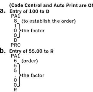
Multiply 100 times 55.00 and print the result. This operation requires three sequences.
(Code Control and Auto Print are ON)
a.
Entry of 100 to DPAl
8 (to establish th e order)
g}the factor
D PRC
b.
Entry of 55.00 to R PAl6 (order)
nthe factor
R
PRC Multiplication take place automatically
c. Pri nti ng the Resu It
The Program Panel will be wired to initiate product readout at order 7. This order was se-lected to accommodate the result of the two largest possible factors (999 x 99.99). In the actual example the result would only require 6 positions. The panel will also be wired to place the decimal between orders 2 and 3, and to stop the readout after order one.
The following examples have been provided to demonstrate the ease of 7816 VERSA-TRONIC code programming once the basic seq uences are mastered.
This sequence would require only
1%0
thsof a second to perform since the digits of entry were read in the Auto Print "OFF"
mode. If the factor 100.00 were to print
(Auto-Print must be "ON") then the time required would be 2%oths of a second. Note that the digits may print or not print as determined by the state of Auto Print. In the event the digits were all non-printed, the entire sequence could be performed (including the accumula-tion) in the time required for the I/O Printer
to tab only
Y2
inch or so, and the delay to thesystem would be nil.
How the Input Orders were Selected
For the Multiplicand and the Multiplier en-tries, the orders selected were 8 and 6 respec-tively. This was to establish the half-cent round-off in the product. Note that with the figure 100 the decimal would fall to the left of order 5 since the "1" was entered at order 8), and with 55.00 the decimal would fall to the left of order 4 (since the first "5" was en-tered at order 6). This would leave 5 and 4 orders remaining to the right of the decimal respectively for each entry. Five and four equals nine (rule of nine), which assures us that the half cent round-off will occur cor-rectly in the Product.
The sequence of codes required to print the Product would be:
*APN Turns on Auto Print PA3
P Selects Product Register PRC
SP
5 5
o
o The Printed result
o
o
*Auto Print must be on for the result to print. If Auto Print had not been on, the P A3 sequence would only transfer the P Register to the buffer and/or Vertipunch (if "ON").
[image:19.618.58.214.431.585.2]Output Components Must Be "ON" to Receive Data from the Processor
It is a rule of 7816 Programming that output will be made only to "on" components. Thus the PA3, PA4 and PA5 commands will have no visual effect if neither Auto Print nor a
VERTIPUNCH is on. These commands will,
however, perform their assigned internal Proc-essor functions. Thus, the P A5 command would transfer a selected register to D and the Buffer even though all output components were off.
Example 3
A quantity multiplied times a price and then chain discounted three times with printing of the final result. The following mathematical sequence is required:
Quantity times price less discount less dis-count less disdis-count equals total. OR 100 x 1.00
==
100.00 - 10% x (100.00)==
(90.00)-10% x (90.00)
==
(81.00) - 1 % x (81.00)==
80.19.If the intermediate products are to be printed then Auto Print can remain on during tbe entire sequence. If not, then Auto Print must be turned "on" and "off" as required. In this instance it is presumed that the first prod-uct and the final prodprod-uct will print but the intermediate products (from the first two dis-counts) will not print.
Following is the code sequence required. (Start with CCN and APN.)
PAl
8
n
0PRC PAl
5
n
RPRC APF PAS P PRe APN PAl 9
i}
N R PReSets up Processor for entry APF Turns Auto Print "off"
Order PAS Sets up output with transfer
P Selects P for transfer to D
Digits PRe Initiates transfer
APN Turns Auto Print "on"
Register Selected PAl Sets up Processor for second discount
Initiate action 9 Order
Sets up Processor for Price entry
n
Second >discount factor (% shifts decimal twoOrder places to left)
Price N *Negative
R Selects R for discount entry
PRC Initiates multiplication Selects Multiplier APF Turns Auto Print "off"
Initiates multiplication PAS Sets up output and transfer to D Turns Auto Print "off" P Selects P for transfer
Sets up Output with Transfer PRe Initiates action Selects P for transfer to D APN Turns Auto Print "on" Initiates action PAl Sets up Processor for entry Turns Auto Print "on" 8 Order
Setsup Processor for first discount entry
~}
Third discount factor OrderFirst discount (% shifts decimal two places to N *Negative
the left) R Selects R for discount entry
PRC Initiates multiplication *Negative PA3 Sets up Processor for readout
Selects Mu!tiplier for entry P Selects P for readout
Initiates multiplication PRe Initiates action (result prints because Auto Print is "on")
In the above example the Processor Program Panel will be wired to readout the product starting no lower than the 7th order. The P A5 hubs will also be wired to retain the Product each time it is transferred to D.
5.
'Writing the
Program
Using the 7816 Layout Sheet
--TVPETRONIq, 281S-181S LAYOUTSHEET : =
I
II=I~ .. ~ --:~-:1:1:1:ltl:1111 ~
i i i
~ :J
~
The 7816 layout sheet is provided to "put on paper" the essential requirements for the Pro-gram. The sheet is divided into six primary sections: PRINTER LAYOUT, FIELD CON-TROL, INPUT ORDER ASSIGNMENTS, REGISTERS, OUTPUT CODE ASSIGN-MENTS and OUTPUT CONTROL PANEL.
Printer Layout Grid
_ ,"~I_~ I~r"'" , ... 1<-"',."' ... ~ ... ~ ., -=1'" ,,, • . " ... ,.~I"'. _""'''U'" .,"''',. .. ~~r. n •• ,.~ ... ~ .... "."' ••••• !~~.
~ 1;: ttl' "tl-<- _~ :
~~1",
{:1»1,;:::'
i: , . ~ f tit ;;'
As with TYPETRONIC 2816 programming, the Printer Layout grid is used to outline all fields of printing. It is recommended that en-tries which affect the Computing Processor operation but do not print, be shown on the layout in parenthesis. Since such entries will not take up printing space they should be written directly above or below printed entries on the form at the point of operation in which they would take effect. As an example: A re-ciprocal is to be multiplied times the quantity
1000 to compute a price per dozen. The
recip-rocal for twelve (.08333) could be shown below the quantity entry thus:
10001\
(.08333)
Though it is not mandatory, the mathemat-ical symbols
(+, -,
X or -7-) can beindi-ca ted on the form.
Printing of the 7816 is 10 horizontal char-acters to the inch and all printing should be accurately noted in the appropriate columns.
Field Control
Required Field Control columns should be filled-in or checked. The operation of the PAl Decimal Verification track (eight) and the Re-store Enable track (seven) should be checked as required. Remember that tracks 7 and 8 will always be enabled when a PAl code is read and that track seven (Restore Enable) must be punched if clearance of manual en-tries is planned. Section 8 describes the prep-aration of Field Control media tape.
Input Order Assignments
2 3 4 5
ENTRY
~
-START DECIMAL
-
_ioo-. ...ENTRY START DECIMAL
17 18 19 20 21
1 0 . . - . -
--The Input Order Assignments section is used to note the location of the start order and of the decimal for external entries (PAl se-quences). In the ENTRY column write the description of each factor (such as Quantity, Price, Discount, Tax, etc.). In the START col-umn write the start order for each factor. (Re-member, the rule of nine is used to determine the start order when round off is required.) In the decimal column write the order of the in-put decimal. This column will determine where a reader "ON" signal from Field Control will be required to insert the decimal.
Registers
UTILIZATION
FI~-+ __ ~-+ ____________________________ ~
GI~-+--+--+ ____________________________ - i
HI~-+ __ +--+ ____________________________ - i
II~-+--+--+ I-... _ ____ _ ~ ______________________ - i
-The REGISTERS section is used to indicate the use of each register (and register splits), as well as the start, decimal and stop orders to be wired on the program panel.
Output Code Assignments
OUTPUT FUNCTION 1 2 3 4 56 78
DECIMAL 00 00 00 00
PA-6 (when zero) 00 00 00 00
pas. 1 00 00 00 00
r - - '
pas. 2
'-
-
-
0£2 00 00 00-
-
-
-
The Processor Output Program Panel
OUTPUT CONTROL PANEL
10 9 8 7 6 5 4 3 2 1 0 0 0 0 0 0 0
F G H I J K P
0 0 0 0 0 0 0 0 0 0 0 0 0 0
0 - - 0 - - 0 ~
~ ~
10 9 8 7 6 5 4 3 2 1
0 0 0 0 0 0 0 0 0 0 51 S2 NO
0 - - 0 - - 0 0----0----0---0 0 0 0 0 0 0 0 0 0 0
~
F G H I J K P
PA5
0 0 0 0 0 0 0 o 0
2 2 2 2 2 2 2
0 0 0 0 0 0 0
LOCK REG.
0 0 0 0 0 0 ~
F G H I J K
0 0 0 0 0 0 ~
CODE LINES
~
I
0 0 0 0 0 0 0 1 2 3 4 5 6 7
DECIMAL PA6
0 0 0 0 0 0 0 0 0 0
NEG 1 pas 1
0 0 0 0 0 0 0 0 0 0
NEG2 pas 2
0 0 0 0 0 0 0 0 0 0
'0 9 8 7 6 5 4 3 2 1
0 0 0 0 0 0 0 0 0 0
Xl X2
~ 0 - - 0 - - - 0 - - 0 - - 0
9 8 J 7 6 5 4 3 2 1
0 0 0 0 0 0 0 0 0 0
The removable Output Program Panel is re-cessed'behind a door located on the left front side of the Processor. This panel is used for providing output signals and is not related in any manner to Processor input. There are eight primary sections to the output Program Panel. These sections are programmed by in-terconnecting specific hubs as prescribed by output requirements. The following informa-tion describes in detail the programming for each Output Control Panel section.
A B
c
o
E F G H J K L M No
p Q Rs
TRegister Start, Decimal and Stop Hubs
10 9 8 7 6 5 4 3 2 1
0 0 0 0 0 0 0 ()
1
( F G H I J K P0 0 0 0 0 0 0 (
<
(1 1 1 1 1 1 1
0 0 0 0 0 0 0 () (
0 - - 0 - - - 0 ~ ( ( (
0 - - 0 - - 0 ~ '0
10 9 8 7 6 5 4 3 2 1
0 0 0 0 0 0 0 0 0 0
Sl S2 NO
0 - - 0 - - 0 0----0----0---0 0 0 0 0 0 0 0 0 0 0
~
F G H I J K P
PA~'
0 0 0 0 0 0 0 o 0
2 2 2 2 2 2 2
0 0 0 0 0 0 0
n~R~
~.-.
-
--."....-
-
...--Two sections of the Control Panel (A, B, C
4-10 and H, I, J 4-10) are used to indicate the
START ORDER, DECIMAL ORDER, and STOP ORDER of each register and its alter-nate or "split" section. A series of three hubs is provided for each register and each register split. The hubs are connected to order and symbol hubs on the panel. When two or more registers have common orders of start, decimal or stop, they may be wired in common. It is not necessary that a specific hub of a register be used for start, decimal, or stop, since the electronic "sweep" of the Program Panel will always be from high order to low order, and connected hubs will always be selected in the
proper sequence. It is recommended however,
that the top hubs (A 4-10 and H 4-10) be used for start orders; the middle hubs (B 4-10 and I 4-10) be used for decimal orders; and the
bottom hubs (C 4-10 and J 4-10) be used for
STOP orders. Doing this will simplify the checking of the program panel.
Order, Symbol and "No Decimal" Hubs
10 9 8 7 6 5 4 3 2 1
0 0 0 0 0 0 0 ~ G C
F G H I J K P
0 0 0 0 0 0 0 ( (
1 1 1 1 1 1 1
0 0 0 0 0 0 0 ( ( (
~ 0 - - 0 - - 0 - - 0 ~ ( (
~ 0 - - 0 - - 0 - - 0 ( « (
10 9 8 7 6 5 4 3 2 1 0 0 0 0 0 0 0 0 0 0 51 52 NO
~ 0 - - 0 - - 0 - - 0 0 0 0
PA4
0 0 0 0 0 0 0 ~ 0 0
F G H I J K P
0 0 0 0 0 0 0 ( 0 PA5 0
2 2 2 2 2 2 2
~O ...;..0 0..-
-..2
..£ 0 o ( J"\ ..(')~-~
--
~--Positions F 1-10 and G 1-3 are used to indicate the order of start, decimal, stop (and when re-q uired "no decimal") of each register and reg-ister split. Appropriate regreg-ister hubs are wired to these hubs to indicate the desired field out-put for each register. The Sl and S2 hubs in-dicate the first and second symbols available for signs and branching. The ND must be wired when no decimal is used for specified reg-isters. The numbers (10 through 1) correspond wi th the ou tpu t orders for the registers.
A
B
c
o
E
F
G
H
Example of Register Wiring
10 9 8 7 6 5 4 3 2 1
In the example above the F, G, and I Registers
are wired to start at order eight, print the decimal at 5 and stop before the first symbol. The Product Register is wired to start at order 10, print the decimal at 5 and stop before the first symbol. Note that "common" hubs are wired together with multiple jumper wires. When desirable, the BUS hubs may be used for connecting hubs in common.
PA4 and PAS Hubs
S1 S2 NO 0---0--0 0 - - 0 - - 0 - - 0 0 0 0
PA4
0 0 0 0 0 0 0
Lt3
F G H I J K P
0 .. PA 5
0 0 0 0 0 0 o 0
2 2 2 2 2 2 2
0 0 0 0 0 0 0
The P A4 and P A5 hubs are wired when either or both functions require retention of an
out-put factor in the initiating register. If this con-nection is not made, the selected register will clear on PA4 or PA5 output.
A
B
c
o
E
F
G
G
H
Lock Register Hubs
-
-
r-""" - - - --
-
-
-
~~-0 0 0 0 0 0 0 F G H I J K P
PA5
0 0 0 0 0 0 0 o 0 2 2 2 2 2 2 2
0 0 0 0 0 0 0
LOCK REG.
0 0 0 0 0 0 0----0---0--0
F G H I J K
0 0 0 0 0 0 0----0---0--0
CODE LINES
I~
0 0 0 0 0 0 0 0
1 2 3 4 5 6 7 8
" r. r. (). ...0. ..n. .n
--
--
-
-
-The LOCK REG section is used for locking selected registers such that their contents can-not be cleared by the CLEAR STORAGE/ RESTORE key operation. When locked, each selected register (F, G, H, I, J and K) will re-tain the accumulation unless transferred out by a PA3, 4 or 5 sequence.
Code Line Hubs
Eight hubs (M 3-10) designate the eight chan-nels of the TYPETRONIC systems code. When the Decimal, P A6, NEG 1 and 2 or POS 1 and 2 are used, these Code Line hubs are wired to the specified code for each function.
-H
J
K
L
M
N
L
M
N
o
Output Code Assignment Hubs
(0, P,
Q
1-10)
DECIMAL PA 6
0 0 0 0 0 0 0 0 0 0
NEG 1 pas 1
0 a 0 a 0 a 0 0 a 0
NEG 2 pas 2
0 a a 0 0 a a a a 0 0 9 8 7 6 5 4 3 2 1
0 a a 0 0 a 0 0 0 0
The symbol hubs are wired to the Code Lines to "set up" each code that will be used for a symbol or function. Symbols with common "bits" in their configuration are wired in common.
In the example below the codes are assigned as follows:
OUTPUT FUNCTION 1,2,3,4,5,6,7,8
DECIMAL period(.) 1,2,4,6,7 PA6 SSKN 1,3,4,7,8 NEG 1 hyphen(·) 7
pas
1 space 5NEG 2 SKN 1,3,8
pas
2 nonePage 23
M
N
0
P
Q
R
Extractor Hubs
-
-
. - . --
-
-
-
-
----~
0 - 0 - - 0
---0-'--0 0 0 0 0 0
NEG I POS I
0 0 0 0 0 0 0 0 0 0
NEG2 POS2
0 0 0 0 0 0 0 0 0 0
'0 9 8 7 6 5 4 3 2 1
0 0 0 0 0 0 0 0 0 0 Xl
I
X2~ 0 0 0 0 -9 8 J 7 ' 6 5 4 3 2 1 0 0 0 0 0 0 0 0 0 0
The Extractor Hubs are used to selectively transfer specified orders of a register as zeros. Thus a Register containing the ten digits 5981237468 could be transferred as 5981230000 or 5080207060. Two levels of extraction may be programmed. When the P A4 code is used, the register selected will transfer specified or-ders as zeros as indicated by Extractor wiring. NOTE: the START, DECIMAL and STOP orders of readout are not affected by Extractor wiring. If the PA4 hubs (I 1-2) are wired, the entire number will remain in the selected Reg-ister after transfer.
a
p
Q
R
s
T
....
-.-
.--
-o~p
--
0 0 0 "0 o· '0" 0 0NEG2 POS2
0 0 0 0 0 0 0 0 0 0
lO 9 8 7 6 5 4 3 2 1 0 0 0 0
~o
----:;-
I
X2
9 8 J 7
6~
0 0 0 0 o 0 0
In the example shown, Xl is wired to trans-fer the first four digits (10-7) of a register as zeros while X2 is wired to transfer the last three (3-1) as zeros. Both Xl and X2 are se-lected with a P A4 sequence, but the digit 2 must also be included to select the X2 level.
Q
R
S
T
Bus Hubs
The hubs connected by lines are common ter-minals used to simplify the wiring of the board. All wires plugged to a given BUS hub series will be common .
A
B
c
D
Complete Program Panel Diagram
OUTPUT CONTROL PANEL
10 9 8 7 6 5 4 3 2
F G H I J K P
0 0 0 0 0 0 0
2 2 2 2 2 2 2
0 0 0 0 0 0 0
LOCK REG.
0 0 0
J
J
j
0---0---0---0F G H
0 0 0 0----0----0--0
:J
0 0
0 0
NEG 2 pos 2
0 0 0 0 0 0 0 0 0 0
10 9 8 7 6 5 4 3 2 1
cw--
0 0 0 , - - .Xl I~
9 8 I 7 6 5 4 3 2 I
0 0 0 0 0 0 0 0 0 0
A B c o E F G H J K L M N 0 P Q R S T
The example Program Panel wiring will enable the following Processor output operations:
1. Register Output
REG F,G,H J,J,P K START 8 9 7 DECIMAL 2 2 none LAST CHARACTER SI SI 3
2. P A4 and PA5 retain factors in transferred registers.
3. I, J, K Registers are locked
4. Output Code Assignments
SYMBOL CODE NAME CODE
DECI MAL period (.) 1,2,4,6,7 NEG 1 hyphen (.) 7
PA6 STOP 1,2,4
pas
1 space 55. Extractor-Will transfer 10, 9, 8, 2 and 1 orders as zeros (selected register will· retain the factor).
The TYPETRONIC Program Sheet
(Form No. DPS 2002)..,""' __ .. __ TV~.T"O",o. _ __.:~_ - 1 --=~-" - -~-1
---.--=::--:-:-
-~~- 1 -
--:1-The TYPETRONIC PROGRAM SHEET is used with the 7816 in the same manner as the 2816. The various input/output columns are first labeled (one column can be used for Proc-essor output) and the codes then sequentially written in a point to point manner. Processor Access and Instruction codes are initiated from OPTIMATIC Reader One or Two and must be written in the proper reader columns along with the TYPETRONIC control and printer codes.
In the next section of this manual, two com-plete programs are described in detail. A care-ful perusal of these examples should clarify 7816 programming techniques.
6.
Programming
Examples
Application One
Computing Requirements
1. Horizontally accumulate up to five
quan-tities of no more than two digits each to a total quantity (maximum three digits). 2. Multiply the total quantity times a price to
derive an Amount.
3. Accumulate line amounts to a Net Total. 4. Accumulate Net Totals to a "daily" Grand
Total of all invoices.
Special Requirements
1. Provide automatic "reverse entry" of a line by using the Selective Skip Off control. 2. Utilize PARAPROCESSING to minimize
control and Processing time.
3. Turn Reader One On from Field Control after the manual entry of each quantity. 4. An automatic signal must indicate if Net
Total has not been cleared after each invoice is completed.
Format
Application requirements have determined that no more than eight lines will ever be written on one invoice and that the average number of lines is four.
It has also been established that no less than three individual quantities (of A, B, C, and D) will be entered on a single line. (For this rea-son the program will use spacing rather than tabulating to pass fields where no quantity is to be entered.)
Punched Output
Punched output will be the Quantity Total and the Amount for each line.
The Layout Sheet
LAYOUT SHEET
OF
SHEET_-,---' __
2.
DATA PROCESSING SYSTEMS
DIVISION OF SCM CORPORATION
DATE xx/xx/xx
INVOICE
NO.~~~~~~~~~~r_·~USTOMER~_V~~~~~~~~~~~~~~~~~~~~~~~~~DPS BRANCH
VSYSTEMS
REP.---,-v~~~~~~~~~~~_ . /PREP'D BY
",..
.
.,.
"----
. APPLICATION
___ / INVOIC,''''G(WITH HORIZONTAL. ADDITION )LIMITS: 15;2" FORM-14" WRITING LINE (10 CHAR. PER INCH)
PRINTER LAYOUT
STD. LlNESPACE: 6.@)& 2 LINES PER INCHINPUT ORDER ASSIGNMENTS
LINE ·NOTATIONS ENTRY START DfCIMAl ENTRY START DECIMAL
1 UNI, ~VAt:'TITI~
7
5
17 2 p~\C'E 5 4- 183 19
20
21
8
22
10 23
11 12 13 25 14 15
16 11
17 18 19 20 21 22 23 24 25 26 27
28
REGISTERS
29
START DECIMAL STOP UTILIZATION
30 31
32 33
34
HI
35
36
II.
T
T
JI
FIELD CONTROL
I 2
' . 3
4
5 6
F2
7G2
[ PUNCHCNEOFF PUNCtI ... TWO OFF 2 1
EEESEEtESEl1ETIEESTIEtIEEEBEHEErEEHITEErETIITITLEItrFtrEEB33HITB3TIiFtrEEB3±IFITma3JfITITmB3RITEE±IEiEITEE[
READ ONEON 3
[
PUNCH ONE Ofr 4
FC2 =~;~;~NOFF: "-'-L-"-1 ... ',-t-t-i-f-f-H--t-++t-..
+-bH-7815 (RESTOREENABLE 7
RIN IN PAl 8 H-!-H+++++H-IH-t-+++++-I""H-1~~+-I""H-r-H-++++++H-I++++++++r-H-+++++++-H++++-H-++-r-H-++-++-H--l-HH-+-+++
H2
LAYOUT NOTATIONS PUNCH ToTAL.. QUANTITV, AMOUNT AND CARR.IA6= ReTUR.N cooc. MA"lC.IMUM ITE.MS:8
12
MARGIN: 21 TAe STOPS: 34-. 40,65.71 \...1 NeSPAC.e : Dou BL.=
K2
P2
B
-
5
QUANTITYTOTAL-FORM DPS 2001
OUTPUT CODE ASSIGNMENTS
OUTPUT FUNCTION
DECIMAL DE.C I MAl. ( • )
PA·6 (when zero) 5 K N
SPAC.E.
NEG.2
OUTPUT CONTROL PANEL
1 0 9 8 7 6 5 4 3 2 1
~-"
0 0 0 0 ~ ( F G H I J K P-
...
W..-
0 0 0 0 1;1'1 1 1 1 1 1 1
w
....
0 0 0 0"-, 0--0----0 ~
10
6
~\7
:.
5 4 3 \ ; 10
~O:~2
00--0----0 ~l 52 ~D
0 0 0 0 0 0
,Y
~
F G H I J K
PA5
0 0 0 0 0 0 o 0
2 2 2 2 2 2 2
0 0 0 0 0 0
LOCK REG.
~
0 0 0 0 0 0---0---0---0G H I J K
0 0 0 0 0 0---0---0---0
~
~ ~
Cf!ELlf~ ~
:"'\
:J
1;9-
f-o
rS-
L
...
"'-
. . DEC~L ... , ..,
\ P~n.
0 NEG 1o ~ POi 1
0 0 0 0 o 0 0
NEG2 POS2
0 0 0 0 0 0 0 0 0 0 0 9 8 7 6 5 4 3 2 1
0 0 (j 0 0 0 0 0 0 0
Xl
I
X2o C 0 - 0 - 0 0 - - - 0 - - - 0 . - 0 - 0 9 8 7 6 5 4 3 2 1
0 0 0 0 0 0 0 0 0 0
619-
~~ra~ o':~,!'foE,,'!o'!!/!f
SYSTEMST V P ETRO N I C®
PROGRAM SHEET
CUSTOMER~~~ ____________________________________________ _
APPLICATION INVOICINC:J DATE XX/X-X/XX INVOICE NO. __ V __________ _
DPS BRANCH
V
PREP'D BYV--
SHEET ~ OF~INDICATE IN THE HEADING BLOCKS BELOW, THE INPUT AND OUTPUT UNITS USED IN THIS PROGRAM
PROGRAM AND OPERATION DETAIL RE-ADER
-:c
READERlI P U NC tCr:. PROGAAM DETAIL- OUTPUTTo turn off SKIP and stop Reader One
1
SKFafter one complete invoice
r
STP Beginning of line pro~ramLine program: condition Code Control On CCN
Auto Print On
APN
Turn Punch One Off PII=
First sequence quantity A
PA
lOrder entry indicator 7
Enter first quantity A ( STP
Quantity A accum. in reg. P p
I nitiate action
PRe
To get to quan. B field
SP
2nd sequence quantity B PAl
Order indicator 7
Enter qua ntity B
<
5TP
Accum. in reg. P I
P
Initiate action
PRe
To get to guano C field - SP 3rd sequence quan!ity C
~-
PAl
Order indicator
7
Enter quantity C
<
5,- PAccum. in Reg. P P
r-1.lli!iate action
PRe
To get tOQuantitv D field
SP
4th seguence guantity D PAl
Order indicator 7
Enter quantity D
<
5 T PAccum. in Reg. P
P
-I nitiat e action
PRe
To get to total quantity field
, e
---
...Turn on punch one PIN
--.Irans~D~.oJ -., PAS"
Select 2nd output of selected R~gister .- Z
Select P - P
Initiate action P RC QlJAN.TOT.
Turn off Punch One P\F
-~
... To get to Price field ... TB
To select Reader Two 5W
O'::Sc.R1 PT,Dtl
--- .~
To select Reader One ,~ SW
To get to Pric_e field .- TB To enter Price .~. _,m _ -,~ PAl Order,entry de~i.g.nation .. ~ .-
5
itiates Skip_ ""~",,,,,~--,,,,,,,"",,,,,,~,,,.,,- .. ~ 51<'"
--1f
SLSK swi!~h On turns 9fJ Skip _ .... SLSKFRever.ses sign 91. entry ___ ., N
3!::!.r
ns off Skie_(!9r posi.!i~e:~1 SKF···CUSTOMER
v---.
PAGE - -~ OF SHEET - - -I PROGRAM AND OPERATION DETAIL BEAOER. 1: REAOE-RJ( PUNc..H:L-A utomatic price entry P~ICc:
To select Reader One 5W
Enter Price into M ultiolier R
R
Initiate multiolication
PRe
To Qet to Amount field
T6
To turn on Punch One PIN
I nitiate Product readout (amou nt)
PA3
Select Product
P
Initiate action
PRC
AMOUNTTo return carriaQe (ounches)
CR
CR
To transfer buffer to F
PAZ
Seled F
F
Initiate ;::)dion
PR.e..
End of line orOQram
To Soec. SkiD to total Droaram 5 S KF
Turn off Punch
P'F
Tab to Amount field
TB4-For total readout
PA3
Select F F
Initiate action
PRe
Indicates total UC
*
L.CReturn CarriaQe CR
To Transfer buffer to G PA~
Select G
<::.
Initiate action PRe
To "zero interro(2'ate" F PA6
Select F F='
in itiate action-if clear skiD occurs PRe If F not clear print / / / / on form
1
/ / / /and Return carriage
I
c.~---Grand Total card
To turn Code Control On CCN
To turn Auto Print On [APN
To condition Punch One Off PIN To Return carria(2'e (conditionin(2') CR
To select output
PA3
Select G
G
Initiate action PR.e
Shift to Upper case
UC
Tvpe Grand total svmbol ~
'*
Shift to lower
LC
Return carriage C~
Stoo reader STP
---NOTES: Line program reoeated eight times. (area between double lines)
Indicates Control and Processor c odes that wi I be maske :I during car iage motior and will nc t therefore, lave any dele Iy effect on tl Ie applicatior . (Note: oth ~r control co e will cause only a 1/30t 1
of one sec ond delay.)
_ ...
--.
PA6 (Zero Interrogation) Control
When a register is addressed with the PA6 code and found to be zero (clear) the SKIP ON code will be generated. On the program sheet it will be seen that if the register is not
clear that four virgules (/ / / /) will print on the form. At the end of a day's operation, if no in-voices have the
"1/11"
marks on them, then it can be safely determined that the operatoralways correctly totalized each invoice. (NOTE: It could just as easily be determined that the buffer always transferred to G (the Grand Total) after the clearing of Net Total. By programming it is quite simple to develop automatic "checking" routines to determine that final totals are properly accomplished by the operator.
The Program Sheet
The PROGRAM AND OPERATION DE-TAIL section of the Program Sheet has in-tentionally been used in this example to de-scribe each program step as it occurs. In actual programming (as will be seen on application two) this would not be necessary. Heavy ver-tical lines have also been drawn along the pro-gram to indicate how PARAPROCESSING conveniently "masks" the various control and processing codes. In this application only two control codes, requiring a total time of only
%
0 ths of a second, have any delay effect onthe Printer operation. The effect of the opera-tion will therefore be that of nearly contin-uous printing.
Application Two
Digital Computing and Storage Requirements 1. Heading
a. Automatic six digit consecutive Invoice Number.
b. Automatic two-digit month.
2. Body
a. Compute Quantity times Price and sup-press printing of the Product (Gross Amount).
b. Apply up to three (two-digits each) Discounts to derive a Net Amount. c. Compute a Commission percent times
the Net Amount to derive a Commission Amount.
d. Manually select distribution of each commission to anyone of six salesmen. e. Compute the Unit Cost times the
Quan-tity to derive the Cost Amount.
f. The Net Amount, Commission Amount, and Cost Amount must be stored for Invoice Total.
3. Footing
a. Sub-total the Net Amount and com-pute a 4
%
Tax to derive the Tax Amount.b. Add in a Freight Charge.
c. Derive the Net Invoice Total, Net Commission Total, Net Cost Total. d. Compute the Invoice Profit (suppress
readout).
4. Daily By-Product Computations
a. Provide daily Grand Totals for:
( 1 ) Tax ( 4) Commission
(2) Freight (5) Cost (3) Invoices (6) Profit
b. Distribute and total commissions for six salesmen.
Page 28
Special Requirements
1. Load Card-a card must be provided for the daily loading of the consecutive invoice number and month into Processor storage. 2. Header and Item "Card-Making" Programs
-programs must be prepared for the auto-matic preparation of Header (customer) and Item (detail) Cards.
3. Daily By-Product Computations-two mas-ter tapes to be used with the daily by-product "Grand Total" and "Commission" tapes must be programmed.
4. Tax, Freight and Invoice Total Cards-cards must be prepared for the Tax, Freight, and Invoice Total programs. 5. Selective ability to manually enter or to
by-pass entry of "Ship To" information in the heading'.
Field Control Requirements
1. Field Control One-Operate with the Header and item programs.
a. Turn Reader One "ON" after two digit "day" is entered.
b. Turn Punch Two "OFF" and Reader One "ON" after Commission Distribution se-lection is entered.
2. Field Control Two-For making Item Cards.
a. Turn On Reader One
( 1) To punch decimal between dollars and cents of price.
(2) After 3 digits of price to the right of the decimal have been punched. (3) After six digit code number is
punched.
(4) After 34 characters of description have been punched.
( 5) To punch decimal between dollars and cents of price.
(6) After three digits of price to the right of the decimal have been punched.
( 7) To punch decimal for commission percent.
(8) After one digit to the right of the decimal has been punched for com-mission percent.
(9) To punch decimal for unit cost. ( 10) After three digits to the right of
the decimal have been punched for unit cost.
3. PAl (External Entry) Reader One On Con-trol-to be used during Loading operation and line item operations.
a. Start Reader One after six digit "invoice number" entry.
b. Start Reader One after two digit "month" entry.
c. Start Reader One after quantity entry. d. Start Reader One after each discount
entry.
e. Start Reader One after dollar amount of freight is manually entered.
f. Start Reader One after cent amount of freight is manually entered.
Format
Application requirements have determined that the maximum number of item lines will be three. The program billing loop will provide the facility for three line items. When less than three lines are typed, the Tax card will initiate a Special Skip of the Program loop back to the beginning.
None, One, Two, or Three discounts may be entered. When less than three are entered, a tape Skip must be manually initiated to by-pass the remaining discount programs.
Punched Output (application two)
TYPETRONIC VERTIPUNCH One
Tape #1 will be an output tape for a tape-to-card converter. (NOTE: Converter "program" codes have not been included since the type of converter is not established.) The converter tape will include: customer number, invoice number, date, item quantities, product codes, net amounts, commission amounts, and cost amounts. This tape will also provide data for tax, freight and invoice total, and profit total detail cards when operated on the converter.
TYPETRONIC VERTIPUNCH Two
Tape #2 will be used for two operations on the 7816 to derive the following daily totals: First Operation: Grand totals of: Taxes,
Freight charges, Net In-voices, Commission, Cost and Profit.
Second Operation: Grand Commission Totals for six salesmen.
Page 30
The Form
A complete form has been prepared to show a typical application invoice.
The Layout Sheet
The Layout Sheet graphically describes the automatic printing and computing operations of the application. Note the a,ssignments given to input orders, registers, and output codes.
The Program Sheets
To aid in the understanding of the programming, individual point to point program-ming sheets have been prepared. They are:
1. Header and Item card-making program
(and daily load card)
2. Heading Program and Operation 3. Line Item Program and Operation 4. Tax Card and Freight Card Programs 5. Total Card Program
6. Daily Commission Total Program 7. Daily Grand Total Program
Operation of the Complete Application
The Program Sheets outline the steps for pre-paring cards and operating the application, since the operator's duties are relatively sim-ple. Following is an abbreviated set of oper-ator instructions (NOTE: The set-up of tab stops, margin, etc. have been omitted since they constitute a "one-time" operation.)
Daily (Before Commencing Billing)
1. Align the first form in the carriage.
2. Check that the tab stops, margin, and line-space are correct.
3. Check the tape supply in each punch and "clear" the punches (by feeding blank tape).
4. Feed enough tape to affix to each VERTI-PUNCH rewind reel.
5. Insert the billing program loop in Reader One.
6. Place the daily load card in Reader Two. Operate the card and manually enter the starting invoice number and month.
Each Invoice
1. Insert a Customer Card in Reader Two. 2. a. If "Ship To" is the same as "Sold To"
start Reader One.
b. If "Ship To" and "Sold To" are differ-ent, turn "on" the SELECTIVE SKIP OFF switch and then start Reader One. 3. a. When the reader stops (from 2.b . . above) fill in the first line of the "Ship To." Start Reader One; when the reader stop fills in the "Ship To" street address. Repeat for the "City and State" line.
b. When Reader One stops (after item 2.a. or 3.a. above) type in the two digit day.
(Reader will start automatically.) 4. When the reader stops, type Customer
Or-der Number. Start ReaOr-der One.
5. When the reader stops, Customer Card is completed.
6. Insert first Item Card in Reader Two and start Reader One.
7. When Reader stops, type Quantity (Reader will start automatically).
8. When the reader stops, type Discounts (if any). (Read~r will start automatically after each Discount.) If less than three Discounts, manually skip Reader One.
9. When the reader stops, enter Salesman distribution selection (Salesman G, H, I, J, K, or P.)
10. Repeat steps 7 through 9 for each Item Card.
11. Insert the Tax Card in Reader Two and start Reader Two.
12. Insert the Freight Card in Read~r Two and start Reader Two.
13. When the reader stops, type the freight amount (Reader will start automatically). 14. Insert Total Card in Reader Two and start Reader Two. When the Total Card is finished, remove the form and repeat steps 1 through 14 for the next invoice.
Page 32
Daily.(atthe
End of Billing)1. Remove by-product tape number one and forward· to the tape-to-card converter location.
2. Manually punch SSKF, SW, SKF, and SW codes in tape number two.
3. Tear off tape number two and place it in Reader One.
4. Place Daily Commissions program in Reader Two.
5. Turn "on" Reader Two.
6. When Read~r Two stops, initiate a .Skip in Reader One.
7. Tape will operate automatically and dis-tribute commissions to each salesman
(printing will not occur). When entire dis-tribution is completed the· six totals will automatically print.
8. Replace tape number two in Reader One. 9. Place Daily Grand Total tape in Reader
Two.
10. Turn on Reader Two.