production in the blood stream, either directly via an effect on mononuclear cells or indirectly via an effect on the alternative complement pathway. Conversely, the majority of the mediators that are potentially elicited in the blood, such as C3a and IL-1, may be simultaneously eliminated during high Sux therapies by an adsorptive or transmembrane mechanism, as discussed above. Other investigations have conRrmed that adsorption is also important in the removal of other inSammatory mediators, such as Factor D and cytokines.
Summary
Dialysers used in contemporary HD are equipped with a wide variety of membranes and within both the cellulosic and synthetic classes, water and soluteSux properties vary widely. For small and middle-sized solutes, abundant clinical data point to the importance of membrane thickness in diffusive mass transfer. The removal of low molecular mass proteins may occur largely by adsorption for some highSux mem-branes, particularly those of hydrophobic synthetic composition. Because many of the mediators of in-Sammation in dialysis patients fall in this low molecu-lar mass protein category, the biocompatibility of a particular membrane must be interpreted in con-junction with its permeability properties.
See Colour Plate 47.
See also: II /Membrane Separations: Membrane Bio-separations. III /Membrane Preparation: Hollow Fibre Membranes; Interfacial Composite Membranes.
Further Reading
Anderstam B, Mamoun A, Sodersten P and Bergstrom J (1996) Middle-sized molecule fractions isolated from uraemic ultraRltrate and normal urine inhibit ingestive behavior in the rat.Journal of the American Society of Nephrology7: 2453}2460.
Cheung AK, Parker C, Wilcox L and Janatova J (1990) Activation of complement by haemodialysis membranes: polyacrylonitrile binds more C3a than cu-prophan.Kidney International37: 1055}1059.
Clark WR, Macias WL, Molitoris A and Wang NHL (1995) Plasma protein adsorption to highly permeable haemo-dialysis membranes.Kidney International48: 481}488. Clark WR, Hamburger RJ and Lysaght MJ (in press) The
effect of membrane composition and structure on solute removal and biocompatibility in haemodialysis.
Kidney International.
Colton C, Henderson L, Ford C and Lysaght M (1975) Kinetics of hemodiaRltration. I.In vitrotransport char-acteristics of a hollowRber blood ultraRlter.Journal of Laboratory and Clinical Medicine85: 355}371. Deppisch R, Gohl H and Smeby L (1998) Microdomain
structure of polymeric surfaces}potential for improving blood treatment procedures.Nephrology, Dialysis and Transplantation13: 1354}1359.
Henderson L (1996) In Jacobs C, Kjellstrand C, Koch K and Winchester J (eds) Biophysics of UltraTltration and HemoTltration, 4th edition, pp. 114}145. Dordrecht: Kluwer Academic Publishers.
Henderson L, Colton C and Ford C (1975) Kinetics of hemodiaRltration. II. Clinical characterization of a new blood cleansing modality.Journal of Laboratory and Clinical Medicine85: 372}391.
Jindal KK, McDougall J, Woods B, Nowakowski L and Goldstein MB (1989) A study of the basic principles determining the performance of several
high-Sux dialyzers.American Journal of Kidney Disease14: 507}511.
Ledebo I (1998) Principles and practice of hemoRltration and hemodiaRltration.ArtiTcial Organs22: 20}25. Leypoldt JK, Cheung A, Agodoa L, Daugirdas J, Greene
T and Keshaviah P (1997) Hemodialyzer mass transfer-area coefRcients for urea increase at high dialysate
Sow rates.Kidney International51: 2013}2017. Lipps B, Stewart R, Perkins H, Holmes G, McLain E, Rolfs
M and Oja P (1967) The hollowRbre artiRcial kidney.
Transactions of the American Society of ArtiTcial Inter-nal Organs13: 200}207.
Lonneman G (1993) Dialysate bacteriological quality and the permeability of dialyzer membranes to pyrogens.
Kidney International(Suppl. 41) S195}S200.
Lysaght MJ (1988) Haemodialysis membranes in transition.Contributions to Nephrology61: 1}17. Vanholder R and DeSmet R (1999) Pathophysiologic
ef-fects of uremic retention solutes.Journal of the Ameri-can Soceity of Nephrology10: 1815}1823.
Diffusion Dialysis
T. A. Davis, Annandale, NJ, USA
Copyright^ 2000 Academic Press
Introduction
Diffusion dialysis is a separation process in which an ion exchange membrane separates a source solution
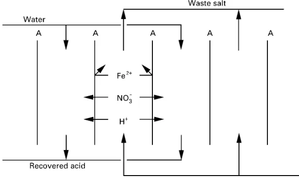
Figure 1 Diffusion dialysis to recover HNO3from pickling solution.
electroplated. Cation exchange membranes are per-meable to bases, and this is utilized to recover NaOH from aluminium etching solutions.
Diffusion dialysis of acids through anion exchange membranes was reported as early as 1964, and was installed on an industrial scale by 1980. There have been many laboratory studies on membrane proper-ties and transport of acid through such membranes. Therefore, the discussions that follow concerning the theory and practice of diffusion dialysis will focus primarily on acid transport through anion exchange membranes. Base dialysis is relatively new, and there is not a large body of knowledge about the mecha-nism of transport, design criteria and performance of that process. Until such information becomes avail-able, it is reasonable to assume that the theory and practice of base dialysis parallels that of acid dialysis. Since ion exchange membranes have an ionically charged polymeric structure, their discrimination be-tween solutes is based on ionic charge. Anion ex-change membranes are easily permeated by anions, but cations are rejected, because the positive ionic change of the membrane matrix repels the cations. Unlike other cations, hydrogen ions are an integral part of the water that pervades the membrane, and hydrogen ions seem to permeate by a different mecha-nism that avoids the rejection of the charged polymer structure. Anion exchange membranes transport acids while rejecting salts.
Figure 1 illustrates diffusion dialysis for recovery of HNO3from a solution also containing Fe(NO3)2. The anion exchange membrane is quite permeable to the NO\3 ions, but an equivalent amount of cations must also pass through the membrane to maintain electroneutrality. Because of their double positive
charge, the Fe2# ions are strongly rejected by the membrane, but the protons are transported rather easily. Thus, a useful separation of acid and salt is achieved.
Background and Theory
Transport in diffusion dialysis is described by Fick’s law:
Flux"!UC [1]
whereCis the concentration difference of the dif-fusing solute (the driving force for diffusion) andUis a mass transfer coefRcient, expressed in units of length time\1. Since the concentrations can be mea-sured only in the bulk solutions, the meamea-sured value of Cis the driving force for diffusion through the membrane and the solution boundary layers next to the membrane. Therefore, an overall mass transfer coefRcientUois needed to describe the observedSux. The reciprocal of the mass transfer coefRcient is the diffusional resistance, and the diffusional resistances of the membrane and the adjacent liquid boundary layers are additive.
1/Uo"1/Um#1/Ul [2]
membranes rapidly, withUvalues of about 10\4to 10\3cm s\1 while salts have U values of about 10\6cm s\1. Therefore, there is sufRcient difference in the diffusion rates to achieve useful separations of acids from salts by diffusion dialysis.
Since solution velocities in commercial dialysers are slow,Ulcould be a signiRcant part ofUo. A rough idea of the resistance in the boundary layer can be estimated by examining the elements of the equation for diffusiveSux through aRlm of liquid:
Flux"!DC/z [3]
where D is the diffusivity of the solute through the solvent, typically about 10\5cm2s\1, and z is the thickness of theRlm of liquid through which diffusion occurs. Spacing between membranes in a commercial dialysis apparatus is somewhat less than 0.1 cm, so liquid Rlm thickness z would probably be about 0.01 cm. ThenD/z"10\3cm s\1, which is aUvalue for the liquidRlm of the same order of magnitude as the typicalUvalues for dialysis membranes.
Consequently, both the membrane and the liquid Rlms in contact with it are likely to contribute to the resistance to diffusion in a real dialysis application, even at rather high solution velocities.
Transport of solvent through dialysis membranes can be great enough to inSuence diffusion dialysis performance. Osmotic forces provide a driving force to transport solvent from the dilute solution to the concentrated solution. However, the diffusing solute can drag along solvent, both in the solvation shells of the ions and by convection, in the direction opposite to that of normal osmosis. Further, osmotic pressures are caused by the concentration difference of nondif-fusing solutes across the membrane, the values of which can be difRcult to determine. Consequently, even the direction of solvent transport can be difRcult to predict in certain circumstances, and prediction of the rate of solvent transport is quite difRcult.
Mathematical analysis of dialysis is rather simple if the assumptions are made that the overall value of
U is independent of Cand that solvent transport is negligible. There are two typical cases that are usually encountered with dialysis in general or with diffusion dialysis.
Case 1 is an experiment done in an apparatus used to measure dialysis coefRcients, i.e. U values. A sample of the membrane is placed between two chambers of equal volume in a stirred cell, with a sur-face area A exposed to both solutions. The source solutionRlls one chamber, and an equal volumeVof pure water, the receiving solution, Rlls the other chamber. Because the volumes of the two solutions are equal, the concentration of the diffusing solute
decreases in the source solution at the same rate as it rises in the receiving solution on the other side of the membrane. The rate of concentration change,dC/dt, is related to theSux, volume and area of the mem-brane by the equations below. On the side containing the receiving solution:
dC/dt"Sux;A/V [4]
and on the side containing the source solution:
dC/dt"!Sux;A/V [5]
To integrate this equation, an expression is needed forSux in terms of concentrations on one side of the membrane. The appropriate expression can be ob-tained by material balance. LetCsrepresent the con-centration of the diffusing solute on the side with the source solution. Then the concentration of the diffus-ing solute in the receivdiffus-ing solution would be
Cr"C0!Cs, whereC0is the initial concentration of the source solution. Now an equation for soluteSux can be written as follows:
Flux"!U;C"!U;[Cs!(C0!Cs)]
"!U;(2Cs!C0) [6]
The differential equation can be integrated to yield:
Cs"C0(1#e\2tUA/V)/2 [7] on the side of the source solution and:
Cr"C0(1!e\2tUA/V)/2 [8] on the side of the receiving solution.
The experiment described in case 1 is a useful technique for measuring values ofUfor a membrane. SufRcient stirring can reduce solutionRlm resistance to negligible levels, and even volume changes are insigniRcant in short experiments. Volume changes and analytical inaccuracy can cause substantial errors if source solution concentrations are used in this de-termination, so determination of theUvalue should be based on the measured concentrations in the re-ceiving solution.
appeal. A commercially useful separation can be achieved with countercurrent Sow of the solutions through the dialyser.
Case 2 is an example of countercurrentSow of the solutions on opposite sides of the membrane. The system operates at steady state so that concentrations do not change with time, but they do change with position along the Sow path of the solutions. To simplify the equations it will be assumed that there is no solvent transport through the membrane and that the source and receiving solutions have the sameSow rate, F. When pure water is used for the receiving stream, the material balance is simply:
Cf"Cd#Cr [9]
where the subscripts represent the feed, depleted and recovered streams respectively. The amount of solute transferred across the membrane is equal to the amount of solute appearing in the recovered stream:
UAC"FCr [10]
Because the Sow rates are equal, the concentration change within a solution compartment is linear with respect to distance along theSow path, so the concen-tration difference across the membrane is equal to the arithmetic mean concentration difference:
C"(Cf#Cd!Cr)/2 [11]
Combining this with the material balance equation yields:
C"Cf!Cr [12]
which can be combined with the transfer equation:
UA(Cf!Cr)"FCr [13]
and rearranged to show the fraction of solute re-covered:
Cr/Cf"U/(U#F/A) [14]
In practice, the values forUare often expressed in the same units as the Sow rate per unit area of membrane, L h\1m\2. For the diffusion of HCl from pickle liquor through Neosepta AFN anion exchange membrane, reported values of U are 8.6 L h\1m\2 for HCl and 0.17 L h\1m\2 for Fe, and a typical value for F/A might be 1 L h\1m\2. With these values the HCl recovery would be 8.6/(8.6#1)" 0.9, and the Fe leakage would be 0.17/(0.17#1)" 0.15. Thus, 90% of the HCl is recovered, and 15% of
the Fe appears in the recovered acid. Leakage of Fe could be reduced to 8% by doubling theSow rates, but HCl recovery would drop to 81%.
The simpliRed equation developed above for countercurrent dialysis is only applicable whenSow rates of both streams in the dialyser are equal. For those more general situations with unequal Sow rates, the log-mean concentration difference would be used as the driving force in Fick’s law.
Deviations from Simple Modelling
Osmotic forces play a key role in the water balance, and water transport through the membrane can in-validate the simple mathematical models described above. The following discussion is based on the re-covery of acid from a steel pickling solution, which is a signiRcant industrial application of diffusion dialy-sis. In the recovery of acid from a mixture with a metal salt the major driving force for osmosis is the difference in concentration of salt across the mem-brane. The osmoticSow of water can cause the vol-ume of the receiving stream to decrease as much as 20% as it passes through a typical industrial dialyser. Therefore, a good mathematical model of diffusion dialysis should account for water transport through the membrane.
The presence of salt in the source solution can substantially affect the concentration of acid in the recovered stream. In diffusion dialysis of metal pickle liquors the source solution has two important compo-nents } the free acid that can diffuse through the anion exchange membrane rather easily and the metal salt that is rejected by the membrane because of repulsion of the metal cations by the Rxed positive charge on the membrane matrix. There are numerous reports of countercurrent diffusion dialysis in which the acid concentration in the recovered stream is higher than the free acid concentration in the feed. Some writers have attempted to explain these obser-vations in terms of osmotic removal of water from the receiving stream, but it seems more plausible that a concentration difference of the common anion pro-duces a driving force for transport of protons through the membrane. That driving force is the Donnan potential (discussed in ‘Membrane Separations: Don-nan Dialysis’) generated by the difference between the activity of anions in the two solutions. That potential difference provides a driving force for proton trans-port in addition to the driving force provided by the difference in concentration of the free acid.
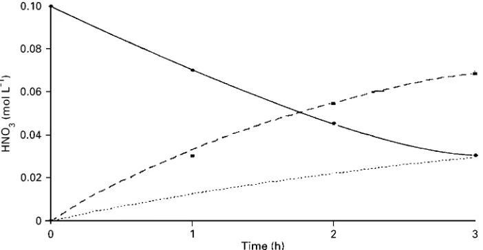
Figure 2 Diffusion dialysis of pure 4 mol L\1HNO
3feed stream (continuous line) with a pure water-receiving stream (dotted line).
Figure 3 Diffusion dialysis of 0.1 mol L\1HNO
3and 5 mol L\1NaNO3feed stream (continuous line) with a pure water-receiving
stream (dashed and dotted lines). Lines calculated as described in the text.
transport due to the concentration difference of the salt with a common anion, withCS as the driving force andUSas the mass transfer coefRcient. The total acidSux can be expressed as the sum of theSux due to individual driving forces as follows:
Total acidSux"UACA#USCS [15] This empirical equation was tested with published data by Edwards, who measured HNO3 concentra-tions on both sides of a Tokuyama AFN membrane in a stirred cell. Graphs of data for three different start-ing compositions are shown in Figures 2}4. In each graph the data at the top connected by the continuous line show the reduction in concentration as acid dif-fuses from the source stream, and the data at the bottom show the increase in acid in the receiving
stream. Figure 2 shows simple diffusion of HNO3, which is well described by the dotted line that was calculated by Fick’s law withUA"12.8 L h\1m\2. But when NaNO3was added to the source solution, Fick’s law withUA"12.8 L h\1m\2(shown in Fig-ure 3 by the dotted line) predicts a much slower appearance of acid than the data indicated. The equa-tion for total acid Sux with values of UA" 12.8 L h\1m\2and U
[image:5.568.112.463.502.684.2]S"0.45 L h\1m\2 shown by the dashed line gave a good correlation of the data. It is interesting to note in Figure 3 that the inSuence of the excess nitrate forced so much HNO3 out of the source stream that its concentration fell below that in the receiving stream. The situation was reversed when NH4NO3was placed in the receiving solution.
Figure 4 Diffusion dialysis of a 2.1 mol L\1HNO
3feed stream (continuous line) against a 4 mol L\1NH4NO3-receiving solution
(dashed and dotted lines).
0.45 L h\1m\2again described the data better than Fick’s law and correctly showed that the appearance of acid in the receiving solution was retarded by the presence of nitrate in that solution. It should be em-phasized that the total acidSux equation is empirical, but it does seem to be a useful way of accounting for the effects of salts on acid Sux and would thus be useful for mathematical modelling of diffusion dialy-sis of acids.
Competing Processes
Diffusion dialysis, like most other membrane pro-cesses, must compete with other processes that can achieve the desired separation. Lime neutralization, sorption on ion exchange resins and bipolar mem-branes are competing processes for the treatment of waste acids from metal pickling. When disposal and replacement acid costs are low, lime neutralization is the most economical alternative. When the recovered acid can be used in a diluted form, sorption on ion exchange resins is attractive. When it is necessary to minimize discharge, bipolar membranes, though ex-pensive, can be the preferred process. Diffusion dialy-sis offers the important advantages of very low oper-ating costs and long membrane life that can exceed 5 years if clean, nonfouling feeds are used. Therefore, if diffusion dialysis can achieve the desired separation and if capital costs are tolerable, diffusion dialysis can be the process of choice for recovering waste acids.
Membranes for Diffusion Dialysis
Modern membranes for acid dialysis are made of anion exchange polymers which have an afRnity for
acids and reject cations other than protons. The anion exchange membranes that are most permeable to acids seem to be those with a very high water content. The water content is important because the high electromobility of protons through water is attribu-table to a transfer mechanism that is not available to other cations. A proton can transfer from a hy-dronium ion to an adjacent water molecule by a mechanism which wasRrst suggested by Grotthus in 1806.
The major suppliers of diffusion dialysis mem-branes and devices are Asahi Glass, who make Selemion DMV, and Tokuyama Corporation who make Neosepta威 AFN and AFX membranes. Since the membrane devices for diffusion dialysis are sim-ilar to those used in electrodialysis, any supplier of electrodialysis equipment is capable of supplying dif-fusion dialysis equipment as well. The supplier with the largest number of installations in the USA is Pure Cycle Environmental Technologies in Palmer, Mass-achusetts, and the largest supplier in Europe is Euro-dia in Paris, France.
Design of Processes and Equipment
Industrial diffusion dialysis usually operates with countercurrentSow of the solutions on opposite sides of the membrane. CountercurrentSow produces the maximum concentration difference over the en-tire length of the membrane and allows recovery of a substantial portion of the most highly diffusive solute while minimizing the transport of the less dif-fusive solutes. Since Suxes in diffusion dialysis are relatively low compared to other membrane pro-cesses, the solution velocity across the membrane surface must also be slow in order to have enough residence time for adequate removal of the solute. Typical solution velocities in diffusion dialysis are about 1 cm min\1. Convective effects due to density changes in the solutions can be important with such low velocities.
Dialysers for industrial applications must be ro-bust, cleanable, efRcient and economical. Industrial diffusion dialysers usually haveSat sheet membranes with some type of spacer to keep the membranes apart and to form solution compartments. The mem-brane arrangement (without showing the spacers) and the directions of solutionSows in a typical diffu-sion dialyser are shown in Figure 1. A single dialyser can contain hundreds of identical, vertically oriented membranes. Membranes and spacers have holes that are aligned to form manifolds, and each spacer has entry ports that connect the solution compartment to the appropriate manifold. This manifolding, which is also typical in electrodialysis, distributes the solution equally to the parallel compartments. The feed solu-tion usually enters the bottom of the dialyser and the solvent usually enters at the top, as shown in Figure 1.
SolutionsSowing through the industrial diffusion dialyser should be free of particulate matter, because the solution velocities are too slow to sweep out particles. The dialyser can be expected to perform maintenance-free for several years if the feed solution is clean and no precipitation occurs within the dialy-ser. A singleRlter on each supply line should sufRce if the feed solution is inherently clean. However, pri-mary and secondaryRltration is recommended if par-ticles are expected to be present in the feed because of the possibility of contamination during the cleaning or replacement of primaryRlter elements.
The low solution velocities that characterize diffu-sion dialysis cause extremely low pressure drops through dialysers, usually just a few kPa. Many dialy-sers can be fed in parallel from a single header tank positioned just above the dialysers. The solutions exiting the dialysers also enter a header tank with adjustable overSow levels. The header tanks should
have covers andRltered vents to avoid the entrance of dust. Transparent tanks or sight glasses positioned close together allow the operator to monitor visually the pressure drop through the dialyser. Density differ-ences of the solutions should be considered in deter-mining the actual pressure head.
In metal Rnishing plants the dialysis process is normally set up to run continuously to treat a small stream of the metal-laden acid in the pickling tank and return the recovered acid to the tank. This allows the dialysis to run as a steady-state process. The waste stream, which typically contains 10% of the acid and 90% of the metals from the feed, is usually neu-tralized to precipitate the metal as hydroxides for disposal or recovery.
It is important that the solutionSow is uniformly distributed to all solution compartments that are fed in parallel. Density changes caused by solute transfer across the membranes are utilized to achieve uniform Sow distribution. The feed solution, which has the highest density, enters the bottom of the dialyser and decreases in density as acid is removed. Osmotic water transport into this concentrated solution also contributes to the decrease in density. The receiving solution increases in density as itSows downward. The uniform gradation in density allows the solutions to approach plug-Sow conditions in each solution compartment.
Entrapped gas can cause Sow disruptions in the receiving solution compartments of acid dialysers. Water entering the top of the receiving solution com-partments contains some dissolved gases (O2, N2, CO2) that can form bubbles in the downward-Sowing solution. Even if the water is not initially super-saturated with dissolved gases, the addition of solute diffusing across the membrane can lead to super-saturation within the receiving stream. The slow downwardSow of solution is not sufRcient to force the bubbles out the bottom of the dialyser, but it could hinder their rise in the compartments, Bubbles eventually reach such a large size that buoyancy for-ces exceed the forfor-ces of surface tension. Then the large bubbles rise and collect in the top of the com-partment and eventually in the entry ports where they block off theSow of water into some of the receiving solution compartment. As more compartments be-come blocked, the solution velocity in the remaining compartments increases. But that increase inSow rate means that the residence time in those open compart-ments is shorter, so the performance of the dialyser deteriorates.
water through a nonwetting microRltration device with a vacuum applied to the opposite side of the microporous membrane. Another remedy is peri-odically to reverse the Sow of the receiving stream and force the bubbles out of the top of the dialyser into a vent tank. Flow reversal can be accomplished easily with a centrifugal pump situated in the line of the receiving solution at the entrance or exit to the dialyser. The header tanks must have sufRcient surge capacity to accommodate the volume of the Sow reversal. Flow reversal for a few seconds is sufRcient
} just long enough to displace any gas that has accumulated in the top of the receiving compartments and entry ports. These two remedies are often used together.
The heat of dilution of the acid can also cause problems of overheating in diffusion dialysis. Because the dialyser acts like a countercurrent heat exchanger, the heat released in the dialyser tends to become trapped inside. When the concentration of acid in the feed is high, the peak temperature, which occurs about halfway through the Sow path, can be high enough to damage the membrane.
Limitations of Diffusion Dialysis
A necessary condition of dialysis is that the solute concentration in the recovery stream must be lower than in the feed stream in order to provide a driving force for diffusion. This is not a real limitation in applications where the diffusing solute is a waste that can be easily discarded. But this condition can be a limitation when the diffusing solute is the desired product, because the product is often recovered at a low concentration. Fortunately, the acid from steel pickling solution can be recycled to the pickling bath at the concentration at which it was recovered. An-other limitation is that the nondiffusing solutes are left in the original solution in a slightly diluted state, which means that the waste volume can be consider-able.
The selectivity of diffusion dialysis membranes for rejecting metal ions is inSuenced by the ionic charge on the metal ion. Metal ions with multiple positive charge are rejected more efRciently than ions with a single charge. However, zinc and some other metal ions form complexes with the anions of the acid. In HCl solutions, zinc forms ZnCl\3 and ZnCl\4 complexes that behave as anions in the anion exchange membrane. These complex ions do not diffuse through the membrane as readily as Cl\ ions do, but they diffuse much faster than Zn2#ions. However, zinc does not form a complex in H2SO4 solution, so zinc is rejected quite well in the sulfate system.
All of the halogens form complexes with some metals. Chloride complexes of Cu, Ga, Fe (ferric forms a much stronger chloride complex than fer-rous), V and Zn have been reported. The existence of a chloride complex does not necessarily mean that HCl cannot be recovered from the metal salt by diffusion dialysis. Since the chloride complexes are rather bulky, they do not pass through the anion exchange membranes as easily as chloride ions do.
Applications
TheRrst important industrial application for dialysis seems to have been for recovery of caustic from vis-cose, hemicellulose, wood-pulping solutions and textile-processing solutions. In the 1930s there were many patents describing dialysers that utilized diaphragms of parchmentized paper and regenerated cellulose. Publications of that era described dialysis as a method for separating crystalloids (sub-stances that form true solutions and are capable of being crystallized) from colloids (small particles in suspension).
By far the most important application for dialysis was begun during the 1940s when Dr. Willem Kolff discovered that treatment of blood by dialysis re-moved urea and other metabolic wastes, and he pro-ceeded to develop the artiRcial kidney. The artiRcial kidney and other conventional dialysis processes are described in detail in ‘Membrane Separations: Dialy-sis in Medical Separations’.
Conclusion
Diffusion dialysis utilizes membranes that contain ion exchange groups, and those were not available until the 1950s. Diffusion dialysis plants have been recovering and recycling acids in Japan since 1980, and many are being installed in the USA, particularly in metal-Rnishing facilities. Acids that have been re-covered include HCl, HF, HNO3, H2SO4 and methanesulfonic. The recovered acid is sufRciently concentrated to be returned to the pickling tank, and the acid-free solution of metal salts requires consider-ably less base to precipitate the metal hydroxides. Recovery of mixed HF and HNO3from the pickling of stainless steel is important because these cids are expensive and cause severe pollution prob-lems if they are discarded. Diffusion dialysis has been applied to the recovery of H2SO4 from aluminium anodizing baths where the trivalent alu-minium cation is well rejected by the anion exchange membrane.
generated by the chemical milling of aluminium air-craft parts. Chemical milling is used to remove metal from aluminium parts, such as curved sections of wing or fuselage that are difRcult to machine with mechanical devices. The part is dip-coated with aRlm of rubber, and then a selected portion of the rubber is stripped away to expose the metal surface. Then the part is immersed in boiling NaOH that rapidly and uniformly dissolves the metal from the exposed sur-face. The dissolved aluminium accumulates in the etch tank as NaAlO2, which must be discarded event-ually. When the NaOH is removed from the solution by dialysis, the NaAlO2 hydrolyses to Al(OH)3 and NaOH. The Al(OH)3 is recovered by Rltration and sold as a pure product, and the released NaOH is returned to the etch tank along with the dialysed NaOH. Dialysis allows recovery of essentially all of the NaOH and completely eliminates the need for disposal of the waste etchant. An industrial installa-tion of base dialysis has been operating
success-fully in a chemical milling plant in California since 1991.
See Colour Plate 48.
Further Reading
Bailey DE (1993) Acid recycling system. US Patent 5 264 123.
Davis TA (1991) Recovery of sodium hydroxide and alumi-nium hydroxide from etching waste. US Patent 5 049 233.
Marshall RD and Storrow JA (1951) Dialysis of caustic soda solutions.Industrial and Engineering Chemistry.
Engineering and Process Development42: 2934}2943. Saddington AW and Julien AP (1938) Dialysis of aqueous
caustic solution. US Patent 2 138 357.
Shigekuni N and Motomura K (1979) Diffusion dialysis method. Japanese Patent 54 136 580.
Zender J (1946) Process and apparatus for dialyzing solu-tions. US Patent 2 411 238.
Donnan Dialysis
T. A. Davis, Annandale, NJ, USA
Copyright^ 2000 Academic Press
Introduction
Donnan dialysis is a separation process that utilizes counterdiffusion of two or more ions through an ion-exchange membrane to achieve a separation. It can also be viewed as a continuous deionization process. For example, water softening can be done with a cation}exchange membrane. Hard waterSows on one side of the membrane, and NaCl brineSows on the other side. Na# ions from the brine diffuse across the membrane and cause the Ca2# and Mg2#ions to diffuse in the opposite direction. Donnan dialysis is usually performed as a continuous, countercurrent process so that a substantial portion of a cation from a dilute solution could be concen-trated into a small volume. Differences in the volumes and concentrations of the two solutions can be exploited to achieve some interesting and useful separations.
Donnan dialysis can be used for changing composi-tions of process or analytical solucomposi-tions, pollution con-trol, and even deionization of a process stream. The deionization process, called ‘neutralization dialysis’,
combines Donnan dialysis through both cation-ex-change and anion-excation-ex-change membranes in one appar-atus with H# and OH\ ions exchanging for the cation and anion of a salt.
In the discussions that follow, the fundamental principles of Donnan dialysis will be presented, and some of its applications and capabilities will be described. The type of equipment and membrane arrangements appropriate for both Donnan dialysis and neutralization dialysis will be presented.