ArtePort Software
User's Manual
Version 1.6
for
SunOS 4.1.2, 4.1.3
and
5.1, 5.2 and 5.3(Solaris 2.1, 2.2 and 2.3)
ArtePort Software
User's Manual
Version 1.6
for
SunOS 4.1.2, 4.1.3
and
5.1, 5.2 and 5.3
(Solaris 2.1, 2.2 and 2.3)
Artecon Inc.
P.O. Box 9000
v
Tradmarks and registered trademarks are proprietary to their respective manufacturers
Copyright © 1993 by Artecon. Inc. - All rights reserved Printed in
Carlsbad. California. U.S.A.
This publication is protected by Federal Copyright Law. with all rights reserved. No part of this publication may be reproduced. stored in a retrieval system. translated. transcribed. or transmitted. in any form. or by any means: manual. electric. electronic. electromechanical. chemical. optical. or otherwise. without prior explicit written permission from Artecon. Incorporated.
ArtePort User's Manual Rev 1.1-12/93
Standard Warranty Information
Artecon Standard Limited Warranty is a Return To Factory
Warranty. Artecon reserves the right to repair, replace, or upgrade at our option with new or reconditioned product which is in good working order; which has been cleaned. lubricated adjusted and tested; and which has had defective or excessively worn parts replaced with new or serviceable used parts.
If one of our products operates improperly during the limited warranty period. we will service it free of charge, provided the complete product is shipped to our designated Service Center at the Customer's expense. This includes all brokerage, customs, handling and insurance charges which may be incurred during the shipping process. The complete defective product must be shipped in the original shipping container. Improper packaging may result in damage which is not covered under the limited warranty and will subsequently void said product limited warranty.
In the event of a System or Subsystem malfunction the customer or his agent should contact the Technical Support Department of Artecon for problem diagnosis. If the Technical Support
Representative determines that the problem cannot be resolved on-site a Return Maintenance Authorization (RMA) will be issued.
Artecon will not accept any parcel without a valid RMA number printed on both the exterior of the Artecon shipping container, and
on the shipping label. Please include a brief description of the problem encountered, in writing, along with the name of your firm' s pertinent technical person.
ArtePort User's Manual
Rev
1.1-12/93
Table of Contents
Standard Warranty Inforlnation ... v
List of Figl.res ... viii
List of Tables ••••••••••••••••.••••••••.•••••••.••.••••.•.•••.••.••••••••••.•••...• ix
Overview ... x
Chapter 1.0 Installing the ArtePort Software •••..•.••....•••.•. 1
1.1 I>escription ... 1
1.1.1 SunOS 4.1.2 - 4.1.3 (Solaris 1.X) Media: ... 1
1.1.2 SunOS 5.1 - 5.3 (Solaris 2.1 ·2.3) ... 2
1.2 Software Installation ... 2
1.2.1 SunOS 4.l.2 - 4.1.3 (Solaris 1.X) ... 2
1.2.2 SunOS 5.1 -5.3 (Solaris 2.l-2.3) ... 3
1.3 Using the ArtePort Software ... ; ... 3
Chapter 2.0 Using tlte ttytool Utility Progralll ... 5
2.1 Introduction ... 5
2.2 tty tool - GtJI ... 5
2.2.1 Edit Hardware Controls ... 7
2.2.2 Edit Input Modes ... 9
2.2.3 Edit Local Modes ... 12
2.2.4 Edit Output Modes ... 16
2.2.5 Edit Special Characters ... 18
2.2.6 Device Name Field ... 21
2.2.7 Rows and Columns Fields ... 22
2.2.8 Signals Field ... 22
2.2.9 File Name Field ... 22
2.2.10 Apply Button ... 22
2.2.11 Get Button ... 22
2.2.12 Colors Button ... 22
2.2.13 Write stty Command ... 23
2.2.14 Write Printcap Entry ... 23
2.3 1Ie1p Windows ... 23
Cilapter 3.0 Contiguration ... 25
3.1 Overview ... 25
3.2 Serial Connections Made Simple ... 25
3.3 DCE or DTE ... 25
3.4 Physical Connection ... 26
3.4.1 Three Wire Cable ... 26
3.4.2 Full Modem Cable ... 28
3.4.3 Null Modem Cable ... 29
3.5 Communications Parameters ... 29
3.5.1 Parity ... 30
[image:5.396.23.370.24.555.2]ArtePort Software User's Manual Rev 1.1-12/93
3.5.2 Data bits ... 30
3.5.3 Stop bits ... 30
3.5.4 Flow control ... 31
3.5.5 Hints ... 31
3.5.6 Example of Printer Installation ... 32
3.5.7 Simple Hardware Flow control for Serial Printers 34 3.6 Adding a Terminal ... 36
3.7 Adding a Modem ... 38
3.8 Adding a Parallel Printer ... 39
Chaptel' 4.0 Troubleshooting ... 41
4.1 Introduction ... 41
Appendix A RS232 Signals ... 42
Appendix B Sample Printcap Entries ... 44
Appendix C Parallel Printcap ...•...•...•..••.•.••••••...••.•••.••• 47
Appendix D Modenl Setup ...•...•....•.•••••••••••...•.•••.•• 49
List of Figures
Figure 2-1. ttytool Graphical User Interface ... 6
Figure 2-2. tty tool Icon ... 6
Figure 2-3. Hardware Control. ... 7
Figure 2-4. Input Modes ... 10
Figure 2-5. Local Modes ... 12
Figure 2-6. Output Modes ... 1 6 Figure 2-7. Special Characters ... 19
Figure 2-8. Example of Help Window ... 24
Figure 3-1. DCE or DTE ... 26
Figure 3-2. Straight Through Cable ... 27
Figure 3-3. Twist Cable ... 27
Figure 3-4. Full Modem Cable ... 28
Figure 3-5. Null Modem Cable ... 29
Figure 3-6. Serial Printer on-line ... 32
Figure 3-7. Serial Printer Cable ... 36
Figure 3-8. Parallel DB·25 Connector ... 40
ArtePort Software User's Manual Rev
1.1-12/93
List of Tables
Table 1-1. Sun Architecture/OS Configurations ... 1
Table 1-2. Customer Release Tape Table of Contents: ... 1
Table 1-3. ArtePoct Device Names ... .4
Table 2-1. Editing Hardware Controls ... 8
Table 2-2. Editing Input Modes ... 10
Table 2-3. Editing Local Modes ... 13
Table 2-4. Editing Output Modes ... 17
Table 2-5. Editing Special Characters ... 19
Table 3-1. Communication Parameters ... 30
Table 4-1. Troubleshooting ... 41
Overview
ArtePort software includes an OpenWindows GUI software package that lets users easHy connect any serial or parallel device to SP ARC systems.
The software provides all the functions of the UNIX stly command and additional features not found in stty. ArtePort software also includes a STREAMS-based driver that interfaces between the kernel and the
Artecon SBus boards.
This document describes the installation and usage of the Artecon ArtePort Software for Sun Workstations. The purpose of this manual is to provide instructions on how to install and use the ArtePort Software with SBus seriaVparallel boards attached to a Sill} Workstation.
This document contains:
• Chapter 1 describes Installing the ArtePort Software.
• Chapter 2 describes Using tty tool Utility Programs.
• Chapter 3 describes Configuration .
• Chapter 4 describes Troubleshooting.
• Appelldix A describes RS232 Signals.
• Appelldix B describes Sample Printcap Entries.
• Appelldix C describes Parallel Printcap.
• Appelldix 0 describes Modem Setup.
• Appelldix E describes Solaris Modems.
ArtePort Software User's Manual
Rev
1.1-12/93
Chapter 1
Chapter 1.0 Installing the ArtePort
Software
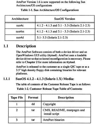
[image:10.396.24.357.122.561.2]ArtePort Version 1.6 is now supported on the following Sun An:hitecture/OS configurations
Table 1-1. Sun Architecture/OS Configurations
Architecture SunOS Version
sun4c 4.1.2 - 4.1.3 and 5.1 - 5.3 (Solaris 2.1-2.3)
sun4m 4.1.2 - 4.1.3 and 5.1 - 5.3 (Solaris 2.1-2.3)
sun4d 5.1- 5.3 (Solaris 2.1-2.3)
1.1
Description
The ArtePort Software consists of both a device driver and an OpenWindows GUI utility (ttytool). ArtePort uses a loadable device driver so that no kernel reconfiguration is necessary. Please refer to Chapter 2 for more information on Uytool.
ArtePort is released to the customer as a single QIC tape or as a 3.5" high density floppy disk containing binaries for relevant platforms.
1.1.1
SunOS
4.1.2 - 4.1.3
(Solaris
LX)
Media:
The table of contents of the Customer Release Tape is as follows
Table 1-2. Customer Release Tape Table or Contents:
Tape File Format Description
1 . dd Copyright
2 tar CMX, README, manpages and
install script
The Customer Release Floppy contains all of the above files in a single bar(l) me.
1.1.2
SuoOS 5.1 - 5.3 (Solaris 2.1 - 2.3)
ArtePort for Solaris 2.1 - 2.3 is released in a package format. Refer to the Sun Manual Ap,plication Packaging and Installation Guide for more information on this format.
t.2
Software Installation.
~"""""I"'I'IIIIIII'III"'~
~
COTE:
The ArtePort SBus card should be ;; installed before the ArtePort ;
~
software installation begins.~
; ;
~
Prior to installing the SBus Card, FIRMLY seat~
~
ALL socketed CHIPS!~
; Place board on af/at, ESD-safe work area with ~
~ connectors hanging over the edges (and while ; ; wearing your ESD wrist strap) FIRMLY push down ~
~ on the big, square Cirrus chips. ;
; . ;
~"""I'I"I'IIIIIIIIIIIIIIII'~
Become super user and start the installation.
#suroot
~""""""""""""""""~
~COTE:
During instailation, the script displays~
~ the default values within square ~
~ brackets. The script accepts the ~
~ default value when you press the ~
~ <Return> key./fyou decide to choose ~
~ an answer other than the default ~
~ value, you need to type in the answer ~
~ at the prompt and press the <Return> ~
~ key. ~
~ ~
~""""""""""""""",\
.2.1
SuoOS 4.1.2 - 4.1.3 (Solaris LX)
#
extracLunbundled
ArtePort Software User's Manual
Rev
1.1-12/93Chapter 1
r · ' I I I I I I I I I I # I I I I I I I I I I # # I I I I I I I I I # # I I I ;
~
f:lTE:
If you are installing the software using an Arteconfloppy~
~ drive, you must first extract the new version of the ~ , "extract_unbundled" commandfrom the release floppy ,
~ diskette. This version of "extract_unbundled" will ~ , recognize the Arteconfloppy drives in addition to the ,
~
devices supported by the normal "extract_unbundled (8)~
~ command. ,
,
~ # bar xvjZf Idevlafd<unit> extract_unbundled'
~,
, Where <unit> is the unit number of the floppy drive (i.e. 0, 1,2, ,'
, or 3), ~
,
,
~ # .Iextract _unbundled ~
""IIIII"IIIIIIIIIIIIIIIIIIIIIIIII'II'~
This installation script will query you for the drive location and device name. It then automatically extracts and installs the correct files for your system.
1.2.2
SunOS 5.1 -5.3 (Solaris 2.1-2.3)
# pkgadd -d /dev/<device>
where <device> is the device you are installing from (e.g. rfdOa when installing from floppy. rmt/O when installing from tape)
The installation script will ask you where you would like the different files to be placed and then installs them.
1.3
Using the ArtePort Software
The ArtePort device driver is now loaded and ready for use. H you are running SunOS 4.1.X. the system does not need to be rebooted (assuming the ArtePort SBus card has already been installed). If
you are using Solaris 2.X. do a boot or.
Refer to Chapter 2 for infonnation on using ttytool. an
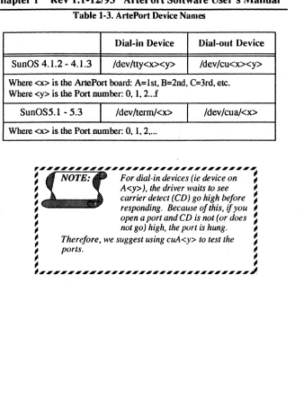
Table 1-3. ArtePort Device Names
Dial-in Device Dial-out Device
SunOS 4.1.2 - 4.1.3 /dev/tty<x><y> /dev/cu<x><y>
Where <x> is the ArtePort board: A=lst. B=2nd. C=3rd. etc. Where <y> is the Port number: O. 1. 2 .. .f
SunOS5.1 - 5.3 /dev/terrn!<x> /dev/cua/<x>
Where <x> is the Port number: O.
1.
2 ....~"""""III"IIIIIIIIII'III'';
~
COTE:
For dial-in devices (ie device on ;; A<y». the driver waits to see ;
~ carrier detect (CD) go high before ~
; responding. Because of this.
if
you ;~ open a port and CD is not (or does ~
; not go) high. the port is hung. ;
~ Therefore. we suggest using cuA<y> to test the ~
; ports. ;
; ;
; ;
I , ____ ' __ '_',"'"_"""",,,,~
ArtePort Software User's Manual
Rev
1.1-12/93
Chapter 2
Chapter 2.0 Using the ttytool Utility
Program
2.1
Introduction
tty tool features a graphical user interface (GUl) designed to allow the user to easily test serial or parallel devices connected to a system. It gives complete control over the terminal interface and provides a terminal window to communicate with the new device. tty tool provides all the functions of the UNIX stty( 1) command
and additional features not found in stty( 1). The information and parameters are in a clear and easy to understand format.Before trying to start ttytool. ensure that the following lines are near the top of your . . cshre file (or .login for Solaris 2.X).
setenv OPENWINHOME=/use/openwin.
setenv W _LIBRARY ]ATH $OPENWINHOMEllib:/usrllib.
2.2
ttytool - G VI
You can bring up ttytool by typing the following command in an OpenWindows Shell Tool or Command Tool:
% ttytool
When first run, it will display a window showing a set of default parameter settings. as shown in Figure 2·1. By entering a device name in the "Device:" field and clicking on "Get", the program will read the current device settings and display them. The device parameters will not be changed until the "Apply" button is pressed.
For example:
SunOS 4.1.2·4.1.3 enter /dev/cuA3
SunOS5.1 ·5.3 enter /dev/term/cua/3
~"""""""""""""""""""'~
~
OOTE:
/feD
i.~
not high the port will hang. We suggest using~
~ cuA (instead of ttya) for testing purposes and/or ~
~ determining the desired parameter settings. ,
IW ... , econ .. 00
( Edit Hub.,. contrOff .• )
( Edit Input Modes ,.)
( tel" Lor.el "oelts ... )
([dlt Sped ... Chwaders ._)
slI •• d 9600 0 row. I) tQlumn. 118764
" .... nla -PtfQdd (17 ""'<Ito"b -t\uDd qhd -c.10QI1 -atsdl -Ignbrll brldnt -Ignpv -parm'k -Inpck ktrlp -lnla -Igna Ian. -lucie
blon -blltll~ -Illoft -Imellbel
Islt -"'tlln kano" -IICISlICho -tKho. -«hok -e<hOflI -natlsh -ta5top -.dtoctl -echoprt -.choM
OIIott -01001( Oftla -«rnl-on«J' -onnt -01111 -otdt'
crO nlO -tilb. bsO \Ito fro
. . . A? kill AU weres. "w rprnl AA flush .0 lnext All SUS, .1 IAV In ... "C quit A\\ stop "'5/AQ eof AD
lOWS: _0 _S::l ... 15; I Enabl.1 §:J §=:J
col ... _0 _83 [!CJ ITCJ@£]
FlI.N .... : _ _ _ _ _ _ _ _
§:]~~
[image:15.396.21.367.21.560.2]( Writ' SHy Command) (Write Prlnkap Entry)
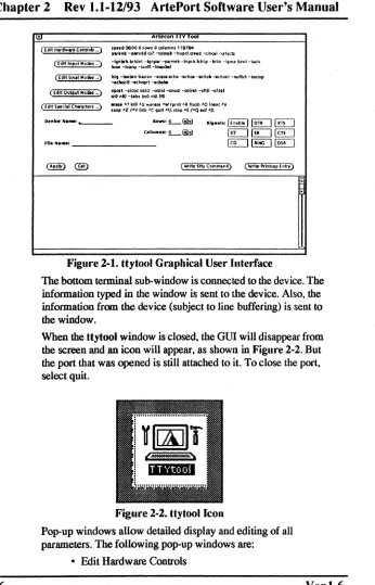
Figure 2-1. ttytool Graphical User Interface
The bottom terminal sub-window is connected to the device. The information typed in the window is sent to the device. Also. the information from the device (subject to line buffering) is sent to
the window.
When the ttytool window is closed. the GUI will disappear from the screen and an icon will appear. as shown in Figure 2-2. But the port that was opened is still attached to it. To close the port. select quit.
Figure 2-2. ttytool Icoll
Pop-up windows allow detailed display and editing of all parameters. The following pop-up windows are:
• Edit Hardware Controls
ArtePort Software User's Manual
Rev 1.1-12/93 Chapter 2
• Edit Input Modes• Edit Local Modes
• Edit Output Modes
• Edit Special Characters
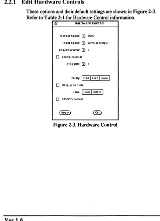
2.2.1 Edit Hardware Controls
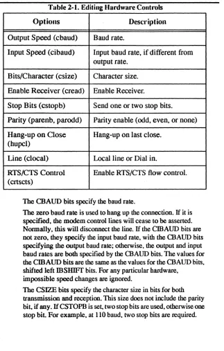
These options and their default settings are shown in Figure 2·3. Refer to Table 2·1 for Hardware Control information.
!9 Hardware Control Output Speed: @l 9600
tnput Speed: @l Same as Output Bits/character: @l 7
o
Enable ReceiverStop Bits: @l 1
rarltv:
I
OddI
EvenI
NoneI
o
Hangup on CloseLine:
I
LocalI
Dial I"I
[image:16.396.29.350.146.589.2]o
RTS/CTS conlrolTable 2-1. Editing Hardware Controls
Options Description
Output Speed (cbaud) Baud rate.
Input Speed (cibaud) Input baud rate, if different from output rate.
Bits/Character (csize) Character size.
Enable Receiver (cread) Enable Receiver.
Stop Bits (cstopb) Send one or two stop bits.
Parity (parenb, parodd) Parity enable (odd, even, or none)
Hang-up on Close Hang-up on last close. (hupcl)
Line (clocal) Local line or Dial in.
RTS/CTS Control Enable RTS/CTS flow control. (crtscts)
The CBAUD bits specify the baud rate.
The zero baud rate is used to hang up the connection. If it is specified. the modem control lines will cease to be asserted. Normally. this will disconnect the line. If the CmAUD bits are not zero. they specify the input baud rate. with the CBAUD bits specifying the output baud rate; otherwise. the output and input baud rates are both specified by the CBAUD bits. The values for
the CmAUD bits are the same as the values for the CRAUD bits.
shifted left mSHIFT bits. For any particular hardware. impossible speed changes are ignored.
The CSIZE bits specify the character size in bits for both transmission and reception. This size does not include the parity bit. if any. If CSTOPB is set. two stop bits are used. otherwise one stop bit. For example. at 110 baud. two stop bits are required.
ArtePort Software User's Manual
Rev 1.1-12/93 Chapter 2
If P ARENB is set. parity generation and detection is enabled and a parity bit is added to each character. If parity is enabled. the P ARODD flag specifies odd parity if set. otherwise even parity is used.If CREAD is set. the receiver is enabled. Otherwise no characters will be received.
If lUJPCL is set. the modem control lines for the port will be
disconnected when the last process with the line open closes it or terminates.
If CLOCAL is set. a connection does not depend on the state of
the modem status lines. Otherwise modem control is assumed.
If CRTScrS is set. and the terminal has modem control lines associated with it. the Request To Send (RTS) modem control line will be raised. and output will occur only if the Clear To Send (crS) modem status line is raised. If the crs modem status line is lowered. output is suspended until crs is raised. Some hardware may not support this function. and other hardware may not permit it to be disabled; in either of these cases. the state of the CRTScrS flag is ignored.
The initial hardware control value after open is CS7. CREAD. PARENB.
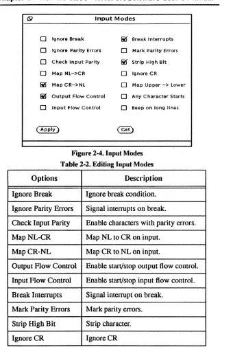
2.2.2 Edit Input Modes
10
19 Input Modes
0 Ignore Break ~ Break Interrupts
0 Ignore Parity Errors 0 Mark Parity Errors
0 Check Input Parity ~ Strip High Bit
0 Map Nl->CR 0 Ignore CR
~ Map CR->Nl 0 Map Upper -> lower
~ Output Flow Control 0 Any Character Starts
0 Input Flow Control 0 Beep on long lines
[image:19.396.23.363.29.544.2]( Apply) ~
Figure 2-4. Input Modes
Table 2-2. Editing Input Modes
Options Description
Ignore Break Ignore break condition.
Ignore Parity Errors Signal interrupts on break.
Check Input Parity Enable characters with parity errors.
MapNL-CR Map NL to CR on input.
MapCR-NL Map CR to NL on input.
Output Flow Control Enable start/stop output flow control.
Input Flow Control Enable start/stop input flow control.
Break Interrupts Signal interrupt on break.
Mark Parity Errors Mark parity errors.
Strip High Bit Strip character.
IgnoreCR IgnoreCR
ArtePort Software User's Manual
Rev
1.1·12/93
Chapter 2
Options Description
Map Upper- Lower Map upper-case to lower-case on input.
Any Character Starts Enable any character to restart output.
Beep on long lines Echo BEL on input line too long.
If IGNBRK is set. a break condition (a character framing error with data all zeros) detected on input is ignored. that is. not put on the input queue and therefore not read by any process. Otherwise.
if BRKINT is set. a break condition will generate a SIGINf and flush both the input and output queues. If neither IGNBRK nor BRKINT is set. a break condition is read as a single ASCn NUL character (0).
If IGNPAR is set. characters with framing or parity errors (other than break) are ignored. If neither IGNP AR nor P ARMRK is set. a framing or parity error (other than break) is read as a single ASCII NUL character (0).
If INPCK is set. input parity checking is enabled. If INPCK is not set. input parity checking is disabled. This allows output parity generation without input parity errors.
If ISTRIP is set. valid input characters are first stripped to 7 bits. otherwise all 8 bits are processed.
If INLCR is set. a received NL character is translated into a CR character.
If IGNCR is set. a received CR character is ignored (not read). Otherwise if ICRNL is set. a received CR character is translated
into a NL character.
If ruQ.,C is set. a received upper-case alphabetic character is translated into the corresponding lower-case character.
If IXON is set. start/stop output control is enabled. A received STOP character will suspend output and a received START character will restart output.The STOP and START characters will not be read. but will merely perform flow control functions.
If IXOFF is set. the system will ttansmit a STOP character when the input queue is nearly full. and a START character when enough input has been read that the input queue is nearly empty
again.
If IMAXBEL is set. the ASCn BEL character is echoed if the input stteam overflows. Further input will not be stored. but any input already present in the input stream will not be disturbed.
If IMAXBEL is not set. no BEL character is echoed. and aU input present in the input queue is discarded if the input stream overflows. The initial input control value is BRKINf. ICRNL.
IXON. ISTRIP. .
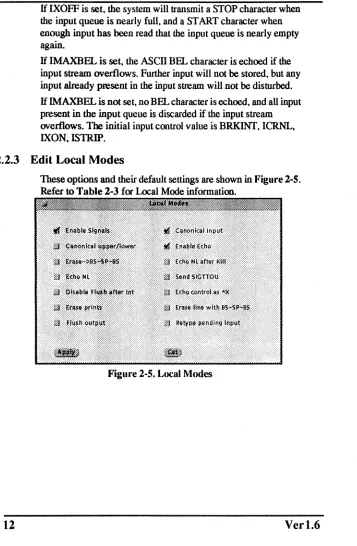
2.2.3 Edit Local Modes
12
[image:21.396.21.378.31.577.2]These options and their default settings are shown in Figure 2-5. Refer to Table 2-3 for Local Mode information.
Figure 2-5. Local Modes
ArtePort Software User's Manual
Rev 1.1-12/93 Chapter 2
Table 2-3. Editing Local Modes
Options Description
Enable Signals (isig) Enable Signals.
Canonical upper/ Canonical upper!1ower presentation. lower (xcase)
Erase-BS-SP-BS Echo erase character as backspace
(echoe) (BS)-space(SP)-backspace (BS).
Echo NL (echon1) Echo NL, even if echo is not set.
Disable Flush after Disable flush after interrupt or quit. Int (no flsh)
Erase prints (echoprt) Echo erase character as character erased.
Flush output (flusho) Output is being flushed.
Canonical Input Canonical input (erase and kill
pro-(Icanon) cessing).
Enable Echo (echo) Enable echo.
Echo NL after Kill Echo NL after kill character. (echoke)
Send SIGITOU Send SIGITOU for background out-(tostop) put. Stop background jobs that attempt
to write to the terminal.
Echo control as "X Echo control characters as "char, (echoctl) delete as "?
Erase line with BS- BS-SP-BS erase entire line on line kill. SP-BS (echok)
If ISIG is set. each input character is checked against the special control characters 1NfR. QUIT. and SUSP. If an input character matches one of these control characters. the function associated with that character is performed. If ISIG is not set. no checking is done. Thus these special input functions are possible only if ISIG
14
is set.
If ICANON is set. canonical processing is enabled. This is affected by the IEXTEN bit (see Special Characters above). This enables the erase. word erase. kill. and reprint edit functions. and the assembly of input characters into lines delimited by NL. EOF. EOL. and EOL2.1f ICANON is not set. read requests are satisfied directly from the input queue. A read will not be satisfied until at least MIN characters have been received or the timeout value
TIME has expired between characters. This allows fast bursts of
input to be read efficiently while still allowing single character input.
The time value repre~nts tenths of seconds. See the Non-canonical Mode Input Processing section for more details.
If XCASE is set. and if ICANON is set. an upper-case letter is accepted on input by preceding it with a character, and is output preceded by a character.
If ECHO is set. characters are echood as received.If ECHO is not set. input characters are not echoed.
If ECHOCIL is not set. all control characters (characters with codes between 0 and 37 octal) are echoed as themselves. If ECHOCIL is set. all control characters other than ASCn TAB. ASCII NL. the START character. and the STOP character. are echoed as 1\ X.
When ICANON is set. the following echo functions are possible:
If ECHO and EOIOE are set. and ECHOPRT is not set. the ERASE and WERASE characters are echoed as one or more ASCn BS SP BS. which will clear the last character(s) from a CRT screen.
If ECHO and ECHOPRT are set. the first ERASE and WERASE character in a sequence echoos as a backslash (\) followed by the characters being erased. Subsequent ERASE and WERASE characters echo the characters being erased. in reverse order. The next non-erase character types a slash (/) before it is echood.
ArtePort Software User's Manual
Rev
1.1·12/93Chapter 2
If ECHOKE is set, the kill character is echoed by erasing each character on the line from the screen (using the mechanism selected by ECHOE and ECHOPRT).If ECHOK is set. and ECHOKE is not set. the NL character will
be echoed after the kill character to emphasize that the line will be
deleted. Note: an escape character or an LNEXT character preceding the erase or kill character removes any special function.
If ECHONL is set. the NL character will be echoed even if ECHO is not set. This is useful for tenninals set to local echo (so-called half duplex).
If ECHOCTL is not set. the EOF character is not echoed. unless it is escaped. Because EOT is the default EOF character. this prevents terminals that respond to EOT from hanging up. If
ECHOCTL is set. the EOF character is echoed; if it is not escaped. after it is echoed. one backspace character is output if it is echoed as itself. and two backspace characters are echoed if it is echoed as" X.
If NOFLSH is set, the nonnal flush of the input and output queues associated with the INTR. QUIT. and SUSP characters will not be
done.
If TOSTOP is set. the signal SIGTTOU is sent to a process that tries to write to its controlling tenninal if it is not in the distinguished process group for that terminal. This signal nonnally stops the process. Otherwise. the output generated by that process is output to the current output stream. Processes that are blocking or ignoring SIGTTOU signals are excepted and allowed to produce output.
If FLUSHO is set. data written to the terminal will be discarded. This bit is set when the FLUSH character is typed. A program can cancel the effect of typing the FLUSH character by clearing FLUSHO.
If PENDIN is set, any input that has not yet been read will be
reprinted when the next character arrives as input.
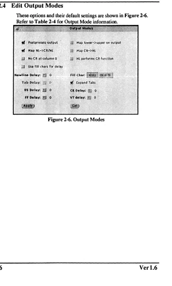
2.2.4 Edit Output Modes
[image:25.396.29.368.34.597.2]These options and their default settings are shown in Figure 2-6. Refer to Table 2-4 for Mode infonnation.
Figure 2-6. Output Modes
ArtePort Software User's Manual
Rev
1.1-12/93Chapter 2
Table 2-4. Editing Output Modes
Options Description
Postprocess Output Postprocess output.
Map NL-CR/NL Map new line (NL) to carriage return (CR) on output.
No CR at column 0 No CR output at column O.
Use fill chars for delay Use fill characters for delay.
Newline Delay Select new-line delays.
BS Delay Select backspace delays.
FF Delay Select form-feed delays
Map lower- upper on Map lower case to upper case on
output output.
MapCR-NL Map CR to NL on output.
NL performs CR function NL performs CR function.
Fill Char Fill is DEL, else is NUL.
Expand Tabs Expand tabs to spaces.
CRDelay Select carriage-return delays.
VTDelay Select vertical tab delays.
H OPOST is set. output characters are post-processed as indicated by the remaining flags. otherwise characters are transmitted without change.
H OLCUC is set. a lower-case alphabetic character is transmitted as the corresponding upper-case character. This function is often used in conjunction with IUCLC.
character is assumed to do the carriage-return function: the
column pointer will be set to 0 and the delays specified for CR will be used. Otherwise the NL character is assumed to do just the line-feed function; the column pointer will remain unchanged. The column pointer is also set to 0 if the CR character is actually transmitted.
The delay bits specify how long transmission stops to allow for mechanical or other movement when certain characters are sent to the terminal. In all cases a value of 0 indicates no delay. H OFll.L is set. fill characters will be transmitted fa: delay instead
of a timed delay. This is useful for high baud rate terminals that
need only a minimal delay. H OFDEL is set. the fill character is
DEL. otherwise NUL.
H a form-feed or vertical-tab delay is specified. it lasts for about
2 seconds.
New-line delay lasts about 0.10 seconds.H ONLREI' is set. the REfURN delays are used instead of the NEWLINE delays. H OFll.L is set. two fill characters will be transmitted.
Carriage-return delay type 1 is dependent on the current column position. type 2 is about 0.10 seconds. and type 3 is about 0.15 seconds. H OFll.L is set. delay type 1 transmits two fill characters. and type 2. four fill characters.
Horizontal-tab delay type 1 is dependent on the current column position. Type 2 is about 0.10 seconds. Type 3. specified by TAB3 or XTABS. specifies that TAB characters are to be expanded into SPACE characters. H OFII.L is set. two fill characters will be transmitted for any delay.
Backspace delay lasts about 0.05 seconds. H OFILL is set. one flll character will be transmitted. The actual delays depend on line speed and system load.
The initial output control value is OroST. ONLCR. XTABS.
~.2.5
Edit Special Characters
18
Special characters have special functions on input and/or output. These options and their default settings are shown in Figure 2-7. Refer to Table 2-5 for Special Characters information.
ArtePort Software User's Manual
Rev
1.1·12/93Chapter 2
Options
Interrupt
Quit
Erase
Special Characters
Interrupt: ~ Qult:~
Erase: "?
Word Erase: "IN Kill: "U
Reprint: ~
Eof: "0
Eol: ,,~
Eo12: ,,~
suspend: ~
Stop: ~
Start: ~
Discard: "0
[image:28.396.43.356.47.596.2]Lit. Next: "V
Figure 2-7. Special Characters
Table 2-5. Editing Special Characters
Description
(C1RL-C or ASCII ETX) generates a SIGINT sig-nal, which is sent to all processes in the distin-guished process group associated with the terminal. Normally, each such process is forced to terminate the program, but arrangements may be made either to ignore the signal or to receive a trap to an agreed-upon location; see sigvec(2).
(C1RL- \or ASCII PS) generates a SIGQUIT sig-nal, which is sent to all processes in the distin-guished process group associated with the terminal. Its treatment is identical to the interrupt signal except that, unless a receiving process has made other arrangements, it will not only be terminated but a core image file (called core will be created in the current working directory.
Options Description
Word (C1RL-Wor ASCII ETB) erases the preceding Erase word. It will not erase beyond the start of a line, as
delimited by a NL, EOF, EOL, or EOL2 character.
Kill (C1RL-U or ASCII NAK) deletes the entire line, as delimited by a NL, EOF, EOL, or EOL2 character.
Reprint (C1RL-R or ASCII DC2) reprints all characters that have not been read, preceded by a NEWLINE.
Eof (C1RL-D or ASCII EOT) may be used to generate an end-of-file from a terminal. When received, all the characters waiting to be read are immediately passed to the program, without waiting for a NEW-LINE, and the EOF is discarded. Thus, if there are no characters waiting, which is to say the EOF occurred at the beginning of a line, zero characters will be passed back, which is the standard end-of-file indication.
Eol (ASCII LF) is the normal line delimiter. It can not be changed; it can, however, be escaped by the Lit.
Next character.
Eo12 (ASCII NUL) is an additional line delimiters, like NL. It is not normally used.
Suspend (C1RL-Z or ASCII SUB) is used by the job control facility to change the current job to return to the controlling job. It generates a SIGTSTP signal, which stops all processes in the terminal's process group.
Stop (C1RL-S or ASCII DC3) can be used to tempo-rarily suspend output. It is useful with CRT termi-nals to prevent output from disappearing before it can be read. While output is suspended, STOP char-acters are ignored and not read.
ArtePort Software User's Manual
Rev 1.1-12/93 Chapter 2
Options Description
Start (ClRL-Q or ASCII DCl) is used to resume output that has been suspended by a STOP character. While output is not suspended. START characters are ignored and not read.
Discard (ClRL-O or ASCII SI) causes subsequent output to be discarded until another DISCARD character is typed. more input arrives, or the condition is cleared by a program.
Lit. Next (ClRL-V or ASCII SYN) causes the special mean-ing of the next character to be ignored; this works for all the special characters mentioned above. This allows characters to be input that would otherwise get interpreted by the system (Example: KILL,
QUI"I)
The character values for Interrupt, Quit. Erase, WErase, Kill, Reprint, Eof, Eol, Eo12, Suspend, Stop, Start, Discard. and Lit.Next may be changed to suit individual tastes. If the value of a special control character is 0, the function of that special control character will be disabled. The Erase, Kill, and Eof characters may be escaped by a preceding character, in which case no special function is done. Any of the special characters may be preceded by the Lit.Next character, in which case no special function is done. If IEXTEN is added to the local modes (this is the default), then all of the special characters are in effect. If IEX1EN is cleared from the local modes, then only the following POSIX.l compatible specials are seen as specials: Interrupt, Quit, Erase, Kill, Eof, NI, EoI, Suspend. Stop, Start. and Cr.
2.2.6 Device Name Field
Type in the name of the ArtePort port you would like to work with.
Example:
SUDOS 4.1.2 - 4.1.3: /dev/cuAO
First port on the first ArtePort board. SunOS5.1 • 53: /dev/cuall
First port on the first ArtePort board.
(cua/O is the parallel port for all except the SB·16(0)
2.2.7
Rows and Columns Fields
Rows and Columns correspond to the size of the terminal's screen. These numbers are used by a number of screen oriented programs such as vi(1).
2.2.8
Signals Field
Each of the fields in this section correspond to a signal on the port. Not all ports support all signals. Clicking on "Get" button will cause the current status of the signals to be displayed. Some
of the signals may be set. Clicking on the "Apply" button will cause ttytool to set the signals according to the values indicated. The signals will then be read and current values displayed.
~.2.9
File Name Field
Type in the name of a me which will hold the output of the Write stty Command or Write Printcap Entry functions.
t2.10
Apply Button
Click this button to apply any changes you have made in ttytool. The changes will be made to the port currently shown in the Device Name Field.
t2.11
Get Button
Oick this button to get the current settings of the port shown in
the Device Name Field. The current settings will be reflected in
the different ttytool windows.
~.2.12
Colors Button
22
Change colors of buttons and other items within the ttytool screen. The color button will only appear on a color monitor. Figure 2-1 illustrates an example of a ttytool on a monochrome monitor.
[image:31.396.15.377.22.463.2]ArtePort Software User's Manual
Rev 1.1·12/93 Chapter 2
2.2.13
Write
sltyCommand
Writes a
sotty
command scriptto the file in "File Name". This can be executed to set the port's values.2.2.14
Write Printcap Entry
Writes a sample printcap entry to the file in "File Name", This may be easily edited into a real printcap entry thus bypassing all the bit twiddling usually associated with configuring serial printers
~IIIIIIIIIIIIIIIIIIIIIIIIIIIIIIIIIIIIIIII
~
. c O T E : This button is not present in the SunOS 5.1-5.3~
~ (Solaris 2.1-2.3) version ofttytool. SunOS 5.1 - ~
~ 5.3 does not use a printcap file. ,
~"'I""II"""""II"""IIIIIIIIIII~
2.3
Help Windows
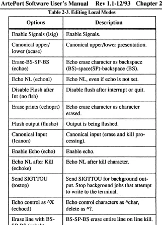
Pop-up windows that allow you to view on-line help are called Help windows. You display a Help window by moving the pointer to the object for which you want help and pressing the <Help> key on the keyboard. The <Fl> key can also be used as the Help key. A pinned Help window is displayed, as shown in the example in Figure 2-8. The object (or a portion of it if the object is large) at the pointer location is displayed in the magnifying glass of the Help window along with explanatory help text.
, ' " " " ,
_____
" " ,___
"
____
,
__
, , , , _ , , ", S
NOTE:r
If
no help is displayed, enter the following command~
~
at the system prompt before executing "ttytoor: ,~
setenv HELPPATH $OPENWINHOMElliblheip~
!9 ttytool: Help
TTVtoo s a uti ty deye oped y Artecon which sets or gets the ter.inal characteristics like speed. baud rate etc of a ter.inal as described by the SunOS' stty(lv). termio(4) and printcap(5) Ian pages.
Please refer to the aboye .an pages for a full description of the functionalitles of this
[image:33.396.20.363.13.593.2]utility.
Figure 2-8. Example of Help Window
•
..
ArtePort Software User's Manual
Rev
1.1·12/93Chapter 3
Chapter 3.0 Configuration
3.1
Overview
Teletypes consisted of an upper-case-only printer. a keyboard and a paper tape reader/punch.
When computers came along. the Teletype became a cheap and readily available tenninal. It gave the programmer access to a keyboard and printer. It also gave him a paper tape reader/punch for program storage. Almost every computer had a RS232 serial interface for hooking up a Teletype.
The RS232 standard uses the tenn "Data Tenninal Equipment' (DTE) for a Teletype-like device and "Data Communication Equipment" (DCE) for modems. The ArtePort device uses the Sun standard ofDTE. Standards concerning DTE's and DCE's are confusing.
, " " " " " " " " " " ' ' " " ' ' ' "
~
COTE:
Throughout this chapter the term~
~ "computer" refers to the ArtePort ~
~ serial ports. ~
~ ~
~"""""""""""""""~
3.2
Serial Connections Made Simple
Connecting a tenninal. modem. or serial printer is a simple procedure. The RS232 standard dermes the serial interface. This section will give you some background and practical advice to help you easily connect serial devices to your ArtePort card.
3.3
DCE
or
DTE
The basic tool for debugging communications problems is the breakout box. It is a small box with several LED's that show the status of the important communication signals. as shown in
I
I
OID
o
RDo
RTSo
CTS ODTRo
DSRo
CDFigure 3-1. DeE or DTE
Sun systems are wired up as DT&. A DCE-type device can be wired indirectly. If you want to connect a D1E you must use a null modem cable. refer to Section 3.4.3.
To determine if you have a DCE or DTE. connect one end· of your breakout box to the device. Leave the other end unconnected. If
LED #2 (1D) lights you have a DTE. If LED #3 (RD) lights you have a DCE. If both LEDs light. you have a broken device. If no LEDs light. you have a cable problem or a broken device.
1.4
Physical Connection
The flCSt step in connecting a terminal. printer. or modem to your computer is to string a cable between the two devices. There are two types of connections. the three wire connection and full modem control.
1.4.1 Three Wire Cable
26
Three wire uses a light cheap cable. No modem control signals are passed between the terminal and the computer. Turning off the terminal does not log you off the computer. This type of connection should not be used for modems. There are two types of three wire connections: straight-through and with a twist. The straight-through cable is shown in Figure 3-2.
[image:35.396.23.373.25.443.2]ArtePort Software User's Manual
Rev
1.1-12/93Chapter 3
2TD 3RD 4RTS 5CfS 6DSR 7Gnd 8CD DeviceFigure 3-2. Straight Through Cable
2TD 3RD 4RTS 5CfS 6DSR 7Gnd 8CD 20DTR Computer
A three wire with a twist contains a built in null modem. as shown
in Figure 3·3.
2TD 3RD 4RTS 5CTS 6DSR 7Gnd 8CD 20DTR Device
Figure 3·3. Twist Cable
2TD 3RD 4RTS 5CfS 6DSR 7Gnd 8CD 20DTR Computer
3.4.2 Full
Modem Cable
The full modem cable passes aU seven signals from the computer to the device. The cable must contain 8 wires (one for ground). The advantage of this connection is to allow you to connect a modem, or other devices that require full modem control, to the computer. The wiring diagram for a full modem cable is shown in
Figure 3-4.
roo-
-2TD 2TD
3RD 3RD
4RTS 4RTS
SITS SITS
6DSR 6DSR
7Gnd 7Gnd
8CD 8CD
20DTR 20DTR
-
[image:37.396.24.377.29.531.2] [image:37.396.25.376.53.599.2]-Device Computer
Figure 3-4. Full Modem Cable
ArtePort Software User's Manual
Rev 1.1-12/93 Chapter 3
3.4.3 Null Modem Cable
If the device you are adding is a DlE. you will need a null modem or the three wire "twist" cable described in Section 3.4.1. A null modem will switch certain signals so that a DTE's signals will look similar to a DCE's signals. The wiring diagram for a null modem cable is shown i..l Figure 3-5.
DB -25
Case Gnd
Tx
Rx
1 1
2~r--2
3 - - - A - 3
Case Gnd
Tx
Rx
RTS
crs
DB -25DSR Connector
Gnd
CD
DTR
[image:38.396.22.337.30.602.2]Shaded areas not supported by all ArtePort products or ports
Figure 3-5. Null Modem Cable
3.5
Communications Parameters
Mter the device is connected. set the communications parameters. These include speed (baud rate), data bits. parity,. and stop bits. The program ttytool is useful in getting the communications parameters. Run the program and set the Device Name to whichever port you are trying to connect. Click on the "Get" button to establish the device. Now try setting them according to the information in your device manual.
Table 3-1. COllilllllllication Parameters
Settings Parameters
Data Bits 8
Parity None
Stop'Bits 2
Try various speeds until the device responds correctly. Common speeds are 1200.2400.9600 and 300. After setting the
parameters. click on the "Apply" button (anyone. they are all the same) and try typing text into the terminal subwindow at the bottom of the ttytool main window. What you type. should appear
00. the device. Some devices. like printers. must receive an entire
line before they print anything.
3.5.1 Parity
Parity is a primitive error detection method. Standard ASCII characters contain 7 bits of data. In even parity. an extra bit is added to make the total number of bits come out even.
H you send no parity data to an even parity device. some of the characters will get parity errors. H some of the data gets through. but some does not. then you probably have a parity problem.
Some printers use the high bit to indicate graphics or italic characters. So if your output appears as: "af3c6efyrl" or "abcdefgh". Parity should be set to none and the characters size to eight.
3.5.2 Data bits
The safest setting for most devices is 8 bit data. Sending 8 bit data to a 7 bit device is not a significant problem. The computer sends 8 bits. the device reads 7. throws away 1 and works about 10% slower.
3.5.3 Stop bits
30
Stop bits are used to signal the end of a character much like a space is used to signal the end of a word. Extra stop bits allows extra space between characters and will work slower.
[image:39.396.17.365.39.513.2]ArtePort Software User's Manual
Rev
1.1-12/93
Chapter 3
3.5.4
Flow control
Computers can send characters faster than modems can receive and re-transmit them. Flow control is used to tell the computer to
slow down. If the flow control is not set up correctly. the modem can hang the port or overwrite data previously received.
The two main flow control methods are "XON/XOFF' and "RTS/ CTS."
rllllll"IIIIIIIIIIIIIIIIIIIII'~
~
COTE:
If you are using XONIXOFF you~
~ cannot use the Xmodem. Ymodem ~
~ or Zmodemfile transfer protocols. ~
~ These protoeals can have the XON ~
~ or XOFF character as part of the ~
~ packet header. ~
~""""""IIIIIIIIIIIIIIIIII~
XON/XOFF are two control characters that.are a holdover from the old Teletype days. They are used to control data being sent by the computer. The modem will send the XOFF character to indicate that it can not handle any more data. When it's able to handle additional data. it will send an XON character.
RTS stands for Request To Send. RTS is a signal generated by the computer to indicate that it's ready to accept data. CTS stands for Clear To Send. CTS is generated by the device to indicate that it's ready for data. Some printers misuse OTR as a type of CTS signal.
For printers that do not support RT~/CTS. connect the printer's OTR line (20) to the ArtePort's CD line (8). Since Artecon's driver monitors Carrier Detect (CD). when CD goes low (ie printer dropped OTR) the port stops sending data. When CD goes
high again. transmission is resumed.
3.5.5
Hints
When starting out. use the / dev / euA <x>
• When setting up a newfype of terminal or printer for the first time. try it out next to the computer. You can change setup parameters or dip switches on the device quickly and not have to run into the next room every time you want to try
something new .
• Some computer installations have "lost cables". That happens when there is a bunch of cables going from the computer into a wall and out in some remote office.
When confronted by a situation like this. short pins 2 and 3 of one of the remote cables. Then go into the computer room and use a ohm meter to find the cable with the shorted pins. Now label the cable and repeat the process.
3.5.6 Example of Printer Installation
~IIIIIIIIIIIIIIIIIIIIIIIIIIIIIIIIIIIII~
~
! : l 0 T E : The following examples are only useful for SunOS~
~ 4.1.2 - 4.1.3 users. SunOS 5.1 -5.2 (Solaris 2.1 - ~~ 2.3) uses a different facility for configuring ,
~ printers. Refer to the Sun document which covers ~
, configuring printers for more details. ,
IIIIIIIIIIIIIIIIIIIIIIIIIIIIIIIIIIIIII~
32
[image:41.396.15.351.39.367.2] [image:41.396.17.372.143.600.2]We will explain how to set up a serial printer on line. as shown in
Figure 3-6. Printers are generally more difficult to set up than terminals.
We unpack the printer, plug it in and tum it on. GVe do not connect it to the computer yet.)
We attach a full modem (straight through) cable to the printer and plug it into a breakout box. LED 2 (ID) lights indicating that the
printer is wired as a DTE. Since the computer is also wired as a DTE we will need a null modem.
We connect the printer to the computer using a full modem cable and a null modem cable.
Printer
Computer
Figure 3-6. Serial Printer OII-lille
ArtePort Software User's Manual
Rev 1.1-12/93 Chapter 3
Next we run the program ttytool. We fill in the "Device Name" entry with / dev / cuA4 and click on the "Get" button.
Ver 1.6
We click on the "Edit Hardware Control" button to bring up the "Hardware Controls" pop-up window. The printer is set for 9600 baud according to the DIP switches. We set the communication parameters to Output Speed:9600. Stop Bits: 2. Bits/Character: 8. and Parity: None.
To test the printer. we type a few lines of "abcdefgh" in the ttytool terminal window. Our printer prints
"!#A%!@%#A%&A%&&,,#@!$%#$%". This is not right. Looking in our printer manual we discover that we have set the wrong DIP switches. We correct the problem and try again.
This time the printer works correctly except everything prints on the same line. Our end-of-line character is <Return>. We need a <line feed> character to space the PlJper up. <line feed> is <Control-1>. so typing <Control-J> a few times will cause the paper to feed up. Normally. the conversion Qf end-of-line into <Return><line feed> is done in the printer filter so we are not worried. Just for fun. we try a <form feed> character and the printer does try to eject a page. but $e paper jams.
The number of stop bits is cut down to one and we try again. Still works.
Just for fun. we try 7 data bits and even parity. Now "abcdefgh" comes out as "abcdefah". So the high bit is used for underline (an undocumented feature of the printer). We set the parameters back to 8 data bits. no parity. '
We ftll in the "File Name" entry with. "/tmp/printcap.add" and click on "Write Printcap Entry" button.
/etc/printcap is edited to add the new entry. The new printer is named "accounting" and has a spool directory of
/var/spool/accounting.
We set up the spool directory with the commands:
% mkdir /var/spool/accounting
% chmod 775 /var/spool/accounting
% chown daemon /var/spool/accounting
% chgrp daemon /var/spool/accounting
The line printer spooler is started using the command:
% lpc start accounting
We test the printer with the command:
% Ipr -Paccounting /etc/fstab
and it works.
The project is complete.
3.5.7 Simple Hardware Flow control for Serial Printers
In this example. we are attaching a serial printer to
port "/dev/ttyA2" on an ArtePort SB-1600. The SB-l600doesnot have "normal" hardware flow control signals (RTS/CfS) so we have to substitute.
1. Make sure that the device is labeled as "remote" in letel
ttytab. In the following line from lete/ttytab. you can see we have changed "local" to "remote".
ttyA2 "/usr/etc/getty std.9600" unknown off remote secure
2. When you reboot the system. soft carrier will be turned off as a result of the above change. If you do not wish to reboot now. you can turn off soft carrier with the following command:.
i ttysoftcar -n /dev/ttyA2
3. The following lete/printcap entry is a good starting point. The printer behaves as desired using this entry. Refer to Appendix B for other printcap entries.
" " " " " " " " " " " " " " " " " " " ' ;
~
COTE:
To prevent Artecon' sSW driver from post-~
~ processing a printJile (which causes problems when ; ; trying to print a postscript file on a postscript ~
~ printer), add the linel entry to the printcap file : ~
~ :ms=-opost:\ ~
~"""""""""""""""""""~
34
i ArtePort Serial Printer Test
testlp:\
:lp=/dev/ttyA2:\
ArtePort Software User's Manual
Rev 1.1-12/93 Chapter 3
:br#9600:\
:sd=/var/spool/testlp:\ :If=lvar/admllpd-errs:
.( """';;;"'11""""""1""""1""'1":
:
~
COTE:
We did come across one limitation. When we~
: : ~ included the following line in our / etc / ~ : : ~ printcapentry, the spooler would be cleared of ~:..
~
all files when the printer was powered off~
.:
~
:of=/usr/lib/lpf:~:
:~.~~"!."!.~.~~~."!.'!."!.~.~."!."!.~~~~'!.~~~~~~~'!.~.'!.~.~~.~."!.~.~.~.j
4. Finally. you must use a special cable to achieve the desired results. as shown in Figur~ 3·7.
For this example. we assume that the DlR signal from the printer goes open (low) when you power ~ printer off. If this is not true
for your particular printer. determine a signal (i.e. DSR. CD. RTS. crS) that does exhibit this behavior and substitute it for DlR in
the pinout. .
DB-25
CaseGnd 1 I CaseGnd
Tx
2~2
TxRx 3 3 Rx
RTS
crs
DB -25 DSR ConnectorGnd 7 7 Gnd
CD
8~8
CDDTR 20 ' 20 DTR
[image:45.396.21.351.41.466.2]Shaded areas not supported by all ArtePort produtts or ports
Figure 3-7. Serial Printer Cable
r r : : r " " " " " " " " " " " " " " " "
~ NOTE: Occasionally, when you spool afile ta a printer that is ~ , currently powered off, the following line will appear on ,
~ the console: ~
~ lpd[1453}: testlp: ~
~ ioctl(TIOCEXCL): No such device or address. The ~
~ easy fix is to execute the following command: ~
~ # lpc restart testlp ~
~ where "testlp" is the name of the printer. ~
~ This will restart the spooler from where it left off. ~ ~1"""""""IIIIIIIIIIIIIIIIIIIIIIII~
3.6
Adding a Terminal
r"""""",""""""""""""~
~
t : J 0 T E : This example is for SunOS 4.1.2 - 4.1.3 users.~
~ Refer to the Sun document which covers adding ,
, devices and drivers for more information on ~
~ adding modems to SunOS 5.1 - 5.3 systems. ,
~""""""""""""""""""'~
36
The following information explains how to add a terminal to your system.
ArtePort Software User's Manual
Rev 1.1-12/93 Chapter 3
You must first connect the device to the computer.
Edit the file /etc/t tytab. Each line in this file corresponds to a device. A typical entry looks like:
ttyA5 "/usr/etc/getty std.9600" vt100\ off local secure
Where:
ttyA5 is the name of the device
"/usr /etc/getty std. 9600" is the command used to start the login process on the terminal. There are more complex options available for the command getty(8); see the getty(8) manual page for more information on this command.
~""""'I'I"'II""~""""'I""'I
I
COTE:
Since the Artecon driver starts getty when CD~
~ goes high, make sure you have the appropriate I
~ cable setup, i.e. straight through, twist or null- ~
I modem I
~llllllllllllllllllllllllllillllllllll~
Ver 1.6
vt 100 is the terminal type. Change this to the correct terminal type.
off indicates that this port is not being used. Change this entry to on.
secure indicates that the terminal is in a secure area and can be used for root logins. Delete the word secure if you wish to disable root logins on this device
After you edit the /etc/ttytab file you must notify the operating system of the changes. Execute the following command as root:
# kill -1 1
At this point. the terminal should have a login prompt.
3.7
Adding a Modem'
"""II""IIIII"""'IIIIIIIII""'II~
~
NOTE: This example is for SunOS 4.1.2 - 4.1.3 users. Refer to~
~ the Sun document which covers adding devices and ~
~ drivers for more information on adding modems to ~
~ '. SunOS 5.1 - 5.2 systems. ~
"IIIIIIIIIIIIIIIIIIIIIIIIIIIIIIIIIIIIII~
38
The following information explains how to add a modem to your system.
You must first connect the device to the computer.
Edit the me / et c / t t yt abo Each line in this me corresponds to a device. A typical entry looks like:
ttyA5 "/usr/etc/getty std.9600" vt100\ off local secure
Where:
ttyA5 is the name of the device
"/usr/etc/getty std. 9600" is the command used to start the login process on the modem. There are more complex options available for the command getty(8); see thegetty(8) manual page for more information on this command.
vt100 is the terminal type. Change this to unknown
off indicates that this port is not being used. Change this entry to on.
remote indicates that the device does support carrier.
secure indicates that the terminal is in a secure area and can be nsedfor root logins. Delete the word secure if you wish to disable root logins on this &vice
Mter you edit the /etc/ttytab file you must notify the operating system of the changes. Execute the following commands as root:
# kill -1 1
# ttysoftcar -a
At this point the modem should be able to accept incoming calls.
Outgoing calls may be placed using the "call" device name
/dev/cuA<number>.
Where:
ArtePort Software User's Manual Rev 1.1-12/93 Chapter 3
number is the port that the modem is
connected to.
See Appendices D and E for modem setup.
3.8
Adding a Parallel Printer
~IIIIIIIIIIIIIIIIIIIIIIIIIIIIIIIIIIIIIII~
~
COTE:
This example is for SunOS 4.1.2 - 4.1.3 users. SunOS~
~ 5.1 - 5.2 uses a different procedure for configuring ~
I printers. Refer to the appropriate Sun document which ~
~ covers adding devices and drivers for more ~
I information on configuring printers. ~
IIIIIIIIIIIIIIIIIIIIIIIIIIIIIIIIIIIIIIII~
Ver 1.6
The device name for the parallel port is / dev / tty Ac. The parallel driver provides output editing functions identical to the ones provided for serial ports. Refer to the termios (4) man page and the ArtePort Hardware Manual for more information.
The following is a minimal /etc/printcap entry that should work for most parallel printers. You should embellish the entry as necessary for 'your site.
To disable postprocessing of printfiles (which causes problems when printing postscript files on a postscript printer). add:
:ms=-opost:\
IplPanasoniciPanasonic 1595:\
:lp=/dev/ttyAc:\
:br#9600:\
:ms=-parenb.cs8.-cstopb,clocal.ignbrk:\ :sd=/var/spool/pan:\
:If=/var/adm/printecerrs:\
:of=/usr/lib/lpf:
See Appendix C for sample printcap entries for parallel port.
FPSTRB
PDATAO
PDATAI
PDATA2
PDATA3
PDATA4
PDATAS
PDATA6
PDATA7
PACK*
PBUSY
PPE
PSLCT
40
*
<
~
PERR*
PINIT*
PSUN*
GND
GND
GND
GND
GND
GND
IndicatesLow True
Indicates from ArtePort Port to Printer
[image:49.396.21.354.39.420.2]Indicates from Printer to ArtePort Port
Figure 3-8. Parallel DB-25 Connector
ArtePort Software User's Manual
Rev 1.1-12/93 Chapter 4
Chapter 4.0 Troubleshooting
4.1
Introduction
[image:50.396.43.331.99.579.2]This section provides reference information for troubleshooting the ArtePort Software. Refer to Table 4-1.
Table 4-1. Troubleshooting
Error Remedy
Printer prints nothing Check the cabling to see if you need a null modem. If not, check the commllnications settings, par-ticularly the speed.
Printer prints garbage Check communication speed.
Some characters Check the parity ~etting.
come out correctly, others do not.
Printer starts out Check the flow control. fine, then prints
gar-bage.
Modem does not The Arte:port driver drops D1R hang-up on close for a short period of time. Some
modems are expecting a longer D1R drop before they will hang up the lin¢. There is usually a modem register (s 10 on a Telebit) that can ~ changed to affect this behavior.
For example: On a Telebit:
42
Appendix A RS232 Signals
RS232 uses a 25 pin connector. Although al125 pins are defmed. only the following 10 are used for asynchronous
commpnications. as shown in Table A.
~IIIIIIIIIIIIIIIIIIIIIIIIIIIIII~
, NOTE: Not all signals are connected for all ~
~ ports. For more information, refer ,
, to the ArtePort SBus Hardware ~
~ User's Manual ,
,
,
,
,
"""""""""""""""'~
ArtePort Software User's Manual
Rev 1.1-12/93 App-A
Table A. RS232 Signals
Pin Signal Description
1 GND Protective Ground
2 TD Transmit Data stream. Data from DTE(Computer) to DCE
3 RD Receive Data stream. Data from DCE to DTE(Computer)
4 RTS Request To Send. This is a signal from the DTE(Computer) to the DCE that tells the DCE that the
DTE(Compu~er) is ready to send data.
5 CTS Clear To Send. Signal from the DCE to the DTE(Computer), telling the DTE(Compllter) that it is OK to send data.
6 DSR Data Set Ready. Signal from the DCE to the DTE(Computer), telling the DTE(Computer) that the DCE has been turned on and is ready to communicate.
7 GND Signal Ground. In most cases, Signal Ground (7) and Protective Ground (l)
are wired together. The difference between the two is of interest only to the purist.
8 CD Data Carrier Detect (also known as DCD). A sigpal from the DCE indicating that it is connected to another DCR "Carrier" is the "I'm
alive" signal sent between two modems.
20 DTR Data Terminal Ready, Signal from the DTE(Computer) to the DCE, telling the DCE that the DTE(Computer) is on and the initialization of the communications. port is complete.
22 RI Ring Indicator. Signal from the DCE indicating that the phone is currently ringing
Appendix B SainpIe Printcap Entries
44
Sample /etc/printcap entries:
r l l l l l l l l l l l l l l l l l l l l l l l l l l l l l l l
~
ONOTE:
For the parallel port, use:~
"~~~c
~
,
,
,
,
,
.,
~""""'I'I'I"IIII"""'II'~
hp4\1bp4mINew lIP LaserJet 4M by FAX Printer:\
:lp=/dev/ttyAe:\
:br#9600: \
:fc#0177777:fs#06021:xc#0177777:xs#040040:\
:ms=-parity,onlcr:\
:mx#O:\
:pw#80 :p1#60: \
:af=/usr/adm/lpd-errs:\
: If=/usr/spool/hp4/ilog: \
:if=/AI/printers/hp4:\
: st=/usr/spool/hp4/status: \
:sd=/usr/spool/hp4:\
:sh:
DMPlCALCOMPI52424P:\
:lp=/dev/ttyAc:\
:sh:\
:sf:\
:mx#O:\
:sd=/var/spool/calcomp:\
:If=/var/spool/calcomp/log:
pslpostscripdPostScripdpostscript emulation on TI microlaser:\
:lp=/dev/ttyAc:\
:sd=/var/spool/ps:\
:br#9600: \
ArtePort Software User's Manual
Rev 1.1-12/93 App-B
Ver 1.6
:mx#O:\ :sh:\ :df=/usrS/wp/slib/wppscript:\ :nf=/var/spool/ps/wpps:\ :gf=/usrS/wp/slib/wppscript:\ :cf=/usr3/wp/shbin/wpp:lplhplhpllhewlett packard emulatioo on 11 microlaser:\
:lp=/dev/ttyA4:\ :sd=/var/spool/hp:\ :br*9600: \ :mx*'O:\ :sh:\ :nf=/var/spool/hp/hpwp:\ :gf=/usrS/wp/slib/wppscript:\ :cf=/usr3/wp/shbin/wpp;
This is a sample of printcap entries used by various printers/ plotters. All entries have been comm~nted out to avoid complaints from the line printer daemon about printers that don't really exist.
*' *' DecWriter over a tty line.
*'
*'
*'
*' lplaplarpalucbarpalLA-180 DecWriter III:\ :br*,1200:fs*,06320:tr=\f:\
:if=/usr/lib/lpf:lf=/usr/adm/lpd-errs:
# typical remote printer entry
*' *'
*'
ucbvaxlvaxlvxlucbvax line printer:\ :lp=:rm=ucbvax:sd=/usr/spool/vaxlpd:\ :If=/usr/adm/lpd-errs: *' *' *' *' # *'
varianlvalBenson Varian:\
46
# :vf=/usr/lib/vpltdmp:\
# :If=/usr/adm/lpd-errs:
# versateclvplVersatec plotter: \
# ':lp=/dev/vpO:sd=/usr/spool/vpd:\
#
:sb:sf:mx#O:pw#106:pl#86:px#7040:py#2400:\
# : of=/usr/lib/vpfW:if=/usr/lib/vpsf:\ # :tf=/usr/lib/vcat:cf=/usr/lib/vdmp:\
# :gf=/usr/lib/vplotf:vf=/usr/lib/vpltdmp:\
# :If=/usr/adm/lpd-errs:
# :tr=\n\n\n\n\n\n\n\n\n\n\n\n\n\
# \n\n\n\n\n\n\n\n\n\n\n\n\n\n\n\
# \n\n\n\n\n\n\n\n\n\n\n\n\n\n\n\
# \n\n\n\n\n\n\n\n\n\n\n\n\n\n\n\
# \n\n\n\n\n\n\n\n\n\n\n\n\n\n\n\
# \n\n\n\n\n\n\n\n\n\n\n\n\n\n\n\
# \n\n\n\n\n\n\n:
ArtePort Software User's Manual
Rev
1.1·12/93
App·C
Appendix C Parallel Printcap
#Printcap Entry from Landscape
hppslNew HP LaserJet I I I Printer PS:\
:lp=/dev/ttyAc:\
:br#9600: \
:fc#0177777:fs#06021:xc#0177777:xs#040040:\ :ms=-parity,onlcr:\
:pw#80 :pH60: \
:af=/usr/adm/lpd-errs:\
:If=/usr/spopl/hpps/ilog:\
:if=/AI/printers/hpiiips:\
:st=/usr/spool/hpps/status:\ :sd=/usr/spool/hpps:\
:sh:
#---#Printcap Entry from Landscape(Word Pecfect)
hpwpllaserlhpiiilNew HP LaserJet III Printer:\
:lp=/dev/ttyAc:\
:br# 9600: \
:fc#0177777:fs#06021:xc#0177777:xs#040040:\ :ms=-parity,onlcr:\
:pw#80 :pH60: \
:af=/usr/adm/lp~-errs:\
:if=/AI/printers/h