Numerical Simulations of Stress Distribution in
Complex Structures with Various Average Volume
Fraction
Elzbieta Gawronska, Robert Dyja, Norbert Sczygiol
Abstract—The paper focuses on stress analysis of periodic structures. In future work, it aims to assess the possibility of fracture occurrence in complex structures based on the performed numerical simulations. The stress analysis is con-ducted by solving the stress equation using the Finite Element Method and is obtained with the use of our authorial software. An example of the compound structure is a gyroid, which is a periodic structure representing an area close to a porous structure. The gyroid composition presents circular struts and a spherical core. The gyroid composition occupies a cube spatially. The length of the cubes side is defined as a unit cell size, and the volume percentage of the struts inside the cube is referred to as volume fraction. Our software module generates periodic cellular lattice structures and simulates stresses distribution in it. The stress model is characterized by dependency between stress and strain, got from an experiment, and by the relationship of strain and displacement, got from geometric considerations. Stress accumulation may result in yield point exceeding locally and, as a result, uncontrolled deformation of the element, and in extreme cases, rupture of continuity of the material. In the paper, we present calculations for three-dimensional areas in which we analyze the stress distribution depending on the degree to which the area is filled with material. The results presented allow assessment of the behaviour of periodic structures under loads.
Index Terms—numerical simulations, stress simulations, FEM, periodic structure, additive manufacturing
I. INTRODUCTION
N
OVEL manufacturing technologies, such as additive manufacturing, have enabled the production of three-dimensional (3D) structures with a wide range of materials and different architectures. The 3D printing was invented in the 20th century, but its industrial use was quite limited. It has changed over the last years. Additive Manufacturing (AM) technologies can use lattice structures and build near-net-shape components layer by layer, and so they are the direct consequences of the work in 3D printing are revo-lutionary to many sectors of manufacturing insofar as they reduce part lead time, cost, material waste, energy usage, etc. [1]. Lattice materials are micro-architectured porous solids and can be manufactured with a broad range of microstructures and length scales. Furthermore, AM has the potentiality to enable up-to-day designing that could not be fabricated using conventional methods or to extend the life of in-service parts through innovative repair methodologies. In situations, where legacy elements are still required for operation and fabricators, but no longer manufactured, forManuscript received July 10, 2018; revised XXXX XX, 2018. E. Gawronska et al. are with the Faculty of Mechanical Engineering and Computer Science, Czestochowa University of Technology, Dabrowskiego 69, 42-201 Czestochowa, Poland, e-mail: [email protected]
instance, aging aircraft systems or older power stations, AM can be used to create that parts. Then, for industrial sectors, one of the crucial values of additive manufacturing can be the ability to reduce weight while maintaining mechanical performance. The advantages are conclusive since AM can result in lower material costs, significant reductions in pro-duction time and increasing design flexibility [2]. AM is transforming approaches in medicine and making work more accessible for architects. For consumer products, artistic and aesthetic designs can be directly manufactured from a CAD file without concern for standard manufacturing practice. When parts with complex internal features or topology have to be produced, many of the established models for traditional production principles can no longer be applicable. AM technology offers an opportunity to create elements previously difficult or impossible to be manufactured with traditional techniques [3].
One of the principal benefits of AM methods is the capac-ity to produce parts which have very complex geometry and which are made by previous methods in a very complicated way. For AM technology to be included in the industrial production of the real components, that high mechanical properties of produced parts are achieved. Moreover, a ge-ometrically defined structure with complex shapes, such a lattice structures, which allows weight reduction, must have sufficient toughness. The final features of manufactured parts are strongly dependent on each laser produced track and layer [4].
It is critical thought to know how new materials, shapes and/or models preserve under load. Therefore many scientists study the gained results of FEM analysis of stress and strain distributions what can make it possible to approximate the mechanical parameters of devices. Thanks to this, the models become useful for comparative analyses of different geometries of tools, which - together with relevant empirical verification studies - make it possible to develop useful geometry [5].
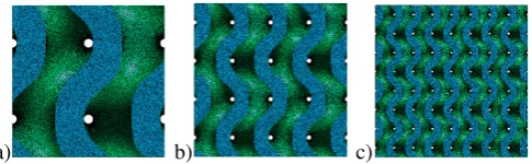
Gyroid structure is a complex formation which has circular and smooth struts within the unit cell continuously varying along the spherical core are presented in Fig. 1. One of the possible application of the gyroid lattice is used it in electronic displays. A thin film of gyroid lattice is bonded to a glass substrate and when infiltrated with a suitable electrolyte, it functions as an electrochromic device [6]. The 3D porous structures with different architectures are also widely used in tissue engineering, especially for orthopedic surgery [7].
a) b) c)
Fig. 1. View through gyroid structures with a) one b) two c) four unit cells per one dimension
is needed for an appropriate purpose. From a mechanical engineering viewpoint, a key advantage offered by cellular materials is high strength and good mechanical properties accompanied by a relatively low mass. These materials can provide excellent energy absorption characteristics, stress distributions as well as good thermal and acoustic insula-tion properties. Designed cellular structures typically exhibit stronger structure strength per unit weight than typical foam structures [8].
A team of researchers at MIT has designed one of the strongest lightweight materials known and has made the simulations with 3-D gyroid forms created from this matter. The results of tensile and compression tests showed that the system could be ten times as strong as steel but much lighter. Their conclusions proved that the crucial aspect of performed tests has more to do with the unusual geometrical shape (gyroid) than with the material itself. The researchers suggest that similar durable, lightweight materials could be made from a variety of matter by creating similar geometric features [9].
The paper focuses on stress analysis of periodic structures. One of the mechanical properties - stress distribution - of the gyroid is reported here. It is a cubic lattice, with a connectivity of the struts per joint, and is undergo load. It aims to distribute the stresses in complex structures based on the performed numerical simulations. The stress analysis is conducted by solving the stress equation using the Finite Element Method and is obtained with the use of our authorial software. An example of the compound structure is a gyroid, which is a periodic structure representing an area close to a porous structure. In the paper, we use gyroid structure which is a homogeneous, isotropic structure, preserving the same mechanical properties in each direction. Isotropy of that structures is very useful because there is no difference in the physical properties regardless of the direction in which they are measured. The forces applied to the element increase stresses in it. Stress accumulation may result in yield point exceeding locally and, as a result, uncontrolled deformation of the element, and in extreme cases, rupture of continuity of the material. We present calculations for three-dimensional areas in which we analyze the stress distribution depending on the degree to which the area is filled with material. We consider a static load case. The results presented allow assessment of the behavior of periodic structures under loads.
II. METHODS
Stress analysis is a general term used to describe the quan-tities stress and strains. It also known as structural analysis. In terms of mechanical properties, the most important
pa-structure and reducing its porosity ensures the development of scaffolds with excellent mechanical properties, which are necessary for counteracting high loading conditions [10].
The stress model is characterized by dependency between stress and strain, got from an experiment, and by the re-lationship of strain and displacement, got from geometric considerations. Stress is related to yield through the physical relationship:
σ=C (1)
where σ is a stress tensor, C is a stiffness tensor and is a tensor of elastic deformation. Physical properties that appear in elasticity tensor can depend on temperature. The relationship from (1) is called generalized Hook’s law. In turn, the strain is related to a displacement through the Cauchy relations [11]:
= 1 2
h
(∇q) + (∇q)Ti (2)
whereq is the displacement vector.
This work focuses on stress distribution in three-dimensional case, so the stiffness tensor becomes:
C=
λ+ 2µ λ λ 0 0 0
λ λ+ 2µ λ 0 0 0
λ λ λ+ 2µ 0 0 0
0 0 0 µ 0 0
0 0 0 0 µ 0
0 0 0 0 0 µ
(3) where
λ= Eν
(1 +ν) (1−2ν) (4)
µ= E
2 (1 +ν) (5)
andE is Young’s modulus,ν is Poisson’s ratio.
In this case, the stress tensor has the following structure:
σT ={σxσyσzτxyτxzτyz} (6)
While the tensor of elastic deformation is given by:
T ={xyzγxyγxzγyz} (7)
whereγxy= 2xy. And the displacement vector is equal:
qT ={u v w} (8)
whereu, v, ware displacements in the direction of x, y,z axes, respectively.
III. RESULTS
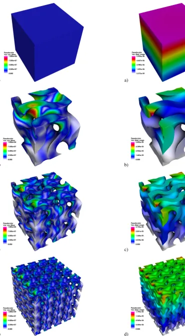
We present the results of stress distribution simulations for a cube, which face has 0.04 m edge length and for the gyroid lattice structures with the same edge length. The material was assumed to be an aluminum alloy. Physical properties for such alloy are following: Young’s Modulus E = 6.9 ·1010 M P a, Poisson’s ratio ν = 0.33, density
ρ= 2700 mkg3. All cubes had fixed bottom faces (all degrees
a)
b)
c)
[image:3.595.331.506.26.737.2]d)
Fig. 2. Stress distribution in a) cube and b) one c) two d) four unit cells of gyroid per one dimension
a)
b)
c)
[image:3.595.83.455.56.730.2]d)
while the total displacement values are shown in Fig. 3. Fig. 4 presents the view of deformed structures. Defor-mation is based on the displacement vector, multiplied by value 250. The red mesh is deformed one and black is an undeformed, shown here for a comparison.
The results show that, unfortunately, in gyroids, we have a generally higher level of stress. Interesting is the fact number of cells has an impact on stress value, because gyroids with more cells have generally a lower value of stress, comparing with gyroid with only one cell. However, in gyroid, a number of cells per volume doesn’t affect the amount of material used (see Table I). So, based on those results, it seems worthwhile to use gyroid structures with a higher number of cells in an element that is under loads.
It was necessary to use finer finite element meshes for gyroids than for the cube since it was necessary to accurately recreate all details of the geometry (see Table I), where geometrical properties of used gyroids are also given. Area fraction here is the ratio ζ defined as the ratio of the area held by a chosen structure a0 to the area of the entire wall a.
ζ= a
0
a (9)
A similar definition of volume fraction γ is used. Full cube has value of 1 for both ratios, while gyroids have substantially smaller ratios.
TABLE I
PROPERTIES OF THE FINITE ELEMENT MESHES
Structure Number of nodes
Number of elements
Area fractionζ
Volume fractionγ
Cube 44567 241939 1 1 Gyroid-1 289543 1195995 0.4336769 0.5215625 Gyroid-2 469847 1823180 0.4203725 0.5223438 Gyroid-4 814535 3044948 0.4265122 0.5228375
IV. SUMMARY
This paper presents results of stress analysis of gyroid structures. As it can be seen gyroid structure under the same load as cube will response with a higher level of stress. However, gyroid structures can vary by the number of cells per length unit and it can be observed that gyroid with a higher number of cells, generally present lower values of stress, while maintaining very similar fill ratio.
REFERENCES
[1] H. Piili, A. Happonen, T. Vist, V. Venkataramanan, J. Partanen, and A. Salminen, “Cost estimation of laser additive manufacturing of stainless steel,” in15th Nordic Laser Materials Processing Conference, Nolamp, Physics Procedia, 2015, pp. 388–396.
[2] C. Yan, L. Hao, A. Hussein, and D. Raymont, “Evaluations of cellular lattice structures manufactured using selective laser melting,”INT J MACH TOOL MANU, vol. 62, pp. 32–38, 2012.
[3] K. V. Wong and A. Hernandez, “A review of additive manufacturing,”
INT J MACH TOOL MANU, vol. 2012, p. 208760, 2012.
[4] K. Monkova and P. Monka, “Some aspects influencing production of porous structures with complex shapes of cells,” in5th International Conference on Advanced Manufacturing Engineering and Technolo-gies: NEWTECH 2017, pp. 267–276.
[5] K. Talaska and D. Wojtkowiak, “Modelling a mechanical properties of the multilayer composite materials with the polyamide core,” in
MATEC Web of Conferences MMS 2017, vol. 157, p. 02052. [6] S. Khaderi, V. Deshpande, and N. Fleck, “The stiffness and strength
a)
b)
c)
d)
[7] D. Ali and S. Sen, “Finite element analysis of mechanical behavior, permeability and fluid induced wall shear stress of high porosity scaffolds with gyroid and lattice-based architectures,”Journal of the Mechanical Behavior of Biomedical Materials, vol. 75, pp. 262 – 270, 2017.
[8] H. L. R.D., Y. Chunze, H. Ahmed, and P. Young, “Design and additive manufacturing of cellular lattice structures,” inInternational Conference on Advanced Research in Virtual and Rapid Prototyping (VRAP), Leiria, Innovative Developments in Virtual and Physical Prototyping 2011, pp. 249–254.
[9] D. L. Chandler. (2017) 3-d-graphene-strongest-lightest-materials. [Online]. Available: http://news.mit.edu/2017/ 3-d-graphene-strongest-lightest-materials-0106
[10] D. P. Byrne, D. Lacroix, J. A. Planell, D. J. Kelly, and P. J. Prendergast, “Simulation of tissue differentiation in a scaffold as a function of porosity, young’s modulus and dissolution rate: Application of mechanobiological models in tissue engineering,” Biomaterials, vol. 28, no. 36, pp. 5544 – 5554, 2007.