Abstract—In this paper, a study of the boundary restrictions at corner's plates for the analysis by the Boundary Element Method (BEM) is presented. It is shown that the plate corner reaction only occurs for a simply supported corner with an internal angle equal to π / 2 and 3π / 2. It can also be observed that the bending moment is null for all the corners studied. With the imposition of these boundary conditions, the results obtained for the boundary tractions, equivalent shear force and bending moments, are in excellent agreement with those obtained by the Finite Element Method (FEM) with refined meshes
Index Terms—boundary element method, plate bending analysis, plate corner reaction
I. INTRODUCTION
W
ITH respect to the application of the BEM to the plate analysis, the development of the method is based on the works of Jaswon,Maiti,&Symm [1] who proposed the solution, via the integral equations, of biharmonic equations and later applying it to the bending plate analysis. Other studies that can be cited are Hansen, [2], Stern [3], Bezini [4], [5], Oliveira Neto & Paiva [6],[7], Paiva & Mendoça, [8], Paiva & Aliabad [9] and Paiva & Venturini [10],[11].In the application of the BEM for plate bending analysis, the boundary is divided into segments called boundary elements and approximation functions are adopted for the displacements and tractions in the domain of each element. The first option is to use the constant element, that is, the displacements and tractions on the boundary of the plate are assumed to be constant in the domain of each element and a single node is located on its midpoint. As in the boundary integral equations for plate bending analysis the plate corner reactions appears, there are additional equations for each plate corner that are usually located at the end of the system of equations obtained for the variables associated to the element nodes. The second option is to use the linear boundary element, with linear approximation for displacements and tractions in the domain of each element. In this case two nodes are associated, usually at the ends of each element and in the corners appear double nodes, with same coordinates but at different sides of the corner. Here also appear difficulties to deal with the corner reaction,
Manuscript received March 10, 2018, revised March 20, 2018. J. B. Paiva is with the University of Sao Paulo, São Carlos Engineering
since now associated with the nodes of the corner we have besides the displacements and their respective derivatives, the equivalent shear forces and bending moments, the corner reaction of the plate that is also associated to the displacements of this same corner, and thus we have a further unknown without an extra equation, since the equations of the displacements and their derivatives are already naturally written. A solution that is usually adopted is to use the discontinuous element for the corner elements, bringing the corner nodes into the elements' domain and then an extra equation associated with an extra variable, the corner nodes equations can now be written. However, this formulation does not provide good results. The main reason is the fact that not every plate corner has a reaction.
In this paper, based on the hypothesis of uniqueness of the stress tensor and using algebraic manipulations, a study is presented on the plate corner, showing which conditions the corner reaction is null. In this study, the same result was obtained as Marcus H. [12] but with a different approach and it is extended to plate corners with other boundary conditions. It was assumed that the sides of the plate corner are not subject to a distributed moment, which would lead to different results from herein.
It is also presented how to write additional equations for each plate corner when the traction and its respective displacement are zero avoiding the singularity of the system of equations.
Plates with different combinations of corner restriction are analyzed and the results compared with those obtained with the finite element method and results show excellent agreement
II. INTEGRAL EQUATIONS
For a plate in bending, the following boundary integral equations can be written, using the alternative formulation of the boundary element method with three nodal displacement parameters [6]:
1
( ) ( ) ( , ) ( ) ( , ) ( ) ( , ) ( ) ( )
( ) ( , ) ( ) ( , ) ( ) ( ) ( , )
( ) ( , ) ( )
c
g
n n ns
N
n n ci ci
i
g
w w
K S w S q S Q w Q m S Q Q m S Q Q d Q
n s
w
V Q w S Q m Q S Q d Q R Q w S Q n
g q w S q d q
(1)
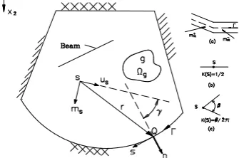
where w, mn and Vn are, respectively, the transverse displacement, the bending moment and the equivalent shear force along the boundary; g(q) and Ωg are the transverse load and the surface where it is applied. The symbol * is
Corners Restrictions and its Application in the
Analysis of Thin Plates by the Boundary
Element Method
used here to indicate the fundamental solution. In this equation K(s) = 1 for internal points s; K(S) = /2
for a point S at a boundary corner, with internal angle ; K(S) = ½ for a point S on a smooth boundary; Rci mns mns
is
the corner reaction.
From (1) the integral representation of the derivative of the displacement with respect to a directionms, of a system of coordinates (ms,us) can be derived as follows:
( , ) ( ) ( , ) ( )
n n
1 2
S S s S
q m
w w w
(S) (S)+ (S) (S)+ S Q w Q S Q Q
K K
m n
m u m
( , ) ( ) * *
ns
n n
S S S
m S Q wQ d (Q)= (Q) w(S,Q) (Q) w(S,Q) d (Q)+
V m
s n
m m m
1
( ) ( , ) ( ) ( , ) ( )
c
g N
ci g
i
ci
R Q g q S q d q
s s
w S Q w
m m
(2)
in which,
1
1
K (S) s i n 2 si n 2
2 8
2
1
K (S) cos 2 cos 2
8
(3)
where is the angle between the coordinate systems (n,s), at the displacement points, and (ms,us), at the source points
(Fig 1).
[image:2.595.55.223.418.529.2]In the numerical application of the BEM, the plate boundary is discretized into segments, called boundary elements, where tractions and displacements are approximated by interpolation functions. In this study, these functions are the same as [6].
Fig. 1. Coordinate systems (n,s) and (ms,us)
Let us consider a generic plate corner and the coordinate systems (n1, s1) and n2, s2) immediately before and after the
corner
Fig. 2. Plate corner
The bending moments mn1, mn2 and the twisting moments,
mn1s1 and mn2s2 can be written as a function of the moments
in relation to the coordinate system (x, y) as follows:
2 2
n1 x y xy
2 2
n1s1 xy y x
m m cos m sin 2m sin cos m m (cos sin ) (m m )sin cos
2 2
n 2 x y xy
2 2
n 2s2 xy y x
m m cos m sin 2m sin cos
m m (cos sin ) (m m )sin cos
(4)
By rewriting the above expressions in matrix form, the following system of equations is obtained:
2 2
n1 x
2 2
n1s1 y
2 2
n 2 xy
2 2
n 2s 2 m
cos sin 2 sin cos
m m
sin cos sin cos cos sin
m
m
cos sin 2 sin cos
m m
sin cos sin cos cos sin
(5)
In order for this system of equations to have a solution, the determinant of the matrix of the increased system of the column of independent terms should be equal to zero, that is:
2 2
n1
2 2
n1s1
2 2
n 2
2 2
n 2s2
cos sin 2 sin cos m
sin cos sin cos cos sin m
0
cos sin 2 sin cos m
sin cos sin cos cos sin m
or:
2
n1s1 n2s2 n2 n1
2sin ( )(m m ) (m m )sin2( ) 0
(6) As:
c
(7)
the determinant expression can be written as:
n1s1 n2s2 c n2 n1 c
(m m )sin (m m ) cos 0 (8)
The relation between the derivatives of the transverse displacement w in the coordinate systems (n1, s1) and (n2, s2)
located on the sides of the corner is given by:
2 1
2 1
w w
n cos( ) sin( ) n
w sin( ) cos( ) w
s s
(9)
By considering the relationship among , and c:
2 c c 1
c c
2 1
w w
n cos sin n
sin cos
w w
s s
(10)
The relationships between the curvatures calculated in relation to these coordinate systems are given by:
2 2
2 2
2 2
2 1
2 2
2 2
2 2 2 2 1 1
2 2
2 2
w w
n n
cos ( ) 2 sin( ) cos( ) sin ( )
w w
sin( ) cos( ) cos ( ) sin ( ) sin( ) cos( )
n s n s
sin ( ) 2 sin( ) cos( ) cos ( )
w w
s s
21
By considering the relationship among
,
and
c:2 2
2 2
2 2
2 1
c c c c
2 2
2 2
c c c c c c
22 2 2 11
c c c c
2 2
2 2
2 1
w w
n cos 2 sin cos sin n
w sin cos cos sin sin cos w
n s n s
sin 2 sin cos cos
w w s s (12)
The relations between the third derivatives of the displacement can be obtained in a similar way:
3 3 2
3 2 2 3
3
2 2 3 2 3 2 2
2 2
2 3 2 3
3 2 2 2 3 3 2
cos 3sin cos 3sin cos sin sin cos cos 2sin cos sin 2sin cos sin cos sin cos sin 2sin cos cos
c c c c c c
c c c c c c c c c c c c c c c
w n w n s w n s w s 3 3 1 3 2 1 1
2 2 3
2
3 2 2 3
1 1 3
3 1
2sin cos sin cos sin 3sin cos 3sin cos cos
c c c c c
c c c c c c
w n w n s w n s w s (13)
III. SUPPORTED-SUPPORTED CORNER
Fig. 3 – Supported-supported plate corner
From the boundary conditions of this corner, the following can be written:
1 2 2 2 2 2 1 2 3 3 3 3 1 2
0 ...(a)
0 ...(b)
0 ...(c)
w w s s w w s s w w s s
(14)
Using (14-a) and (10) the following can be obtained: 1 2 0 w w n n
As mn1= mn2=0 the following also can be obtained that 2 2 1 0 w n , 2 2 2 0 w n
(15) therefore:
2 2
2 2
1 1 2 2
( w) ( w) 0
s n s n
(16) Substituting (14-b) and (15) in (12) the following equation can be obtained:
2 2
c c c c
2 2
2 2
c c c c c c
22 2 2 1 1
c c c c
0 cos 2 sin cos sin 0
w sin cos cos sin sin cos w
n s n s
sin 2 sin cos cos
0 0
Evaluating the matrix product, the following relationships are obtained: 2 c c 1 1 2 2 2 2 c c
1 1 2 2
2
c c
1 1
w
2 sin cos 0 ...(a) n s
w w
(cos sin ) ...(b)
n s n s
w
2 sin cos 0 ...(c) n s (17)
For c 2 or c 32 one has that
2 2
1 1 2 2
w w 0
n s n s
, that is, the corner reaction is zero. Finally, for c c
3 or 2 2 , 2 2
1 1 2 2
w w
n s n s
and then the corner reaction exists and is nonzero. Thus, for this corner, the displacements, their derivatives, the corner reaction and the bending moments mn
are equal to zero.
By substituting the third derivatives given by (14-c) and (16) in the relation given by (13) we obtain:
3
3 2 2 3
3 2
2 3 2 3 2 2
2 3 2 3 2
3 2 2 2
cos 3sin cos 3sin cos sin
sin cos cos 2sin cos sin 2sin cos sin cos
0
sin cos sin 2sin cos cos 2sin cos sin
0
c c c c c c
c c c c c c c c c c c c c c c c c c c
w n w n s 3 3 1 2 3 2
3 2 2 3
1 1
0 cos
sin 3sin cos 3sin cos cos
0
c
c c c c c c
w n w n s (18) the following equations can then be obtained:
3 3 3
3 2
3 3 2
2 1 1 1
3 3
2 3 2
3 2
1 1 1
3 3
2 3
2 3
2 2 1
cos 3sin cos ....(a)
sin cos ( sin 2sin cos ) 0 ....(b)
sin cos ( cos
c c c
c c c c c
c c
w w w
n n n s
w w
n n s
w w
n s n
3 2 2 1 1 3 3 3 2 3 2
1 1 1
2sin cos ) ....(c)
sin 3sin cos 0 ....(d)
c c c
c c c
w n s
w w
n n s
(19)
Equations.(19-b) and (19-d) can be written as:
(20)
In order for this system of equations to have a solution other than the zero solution, the determinant of the matrix of the coefficients of the system must be null.
2 3 2
3 2
sin cos sin 2sin cos
0
sin 3sin cos
c c c
c c (21) That is: 2 4
3sin 4sin 0 0, ,
3
c c or c c c
It follows that for
c other than 0, π and π/3,3 3
3 2
1 1 1
0
w w
n n s
. And consequently, the equivalent shear forces are zero on both sides of the corner. These results verify (8).
3
3
2 3 2
1
3 2 3
2
1 1
sin cos sin 2sin cos 0
0
sin 3sin cos
c c c c c
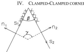
IV. CLAMPED-CLAMPED CORNER
[image:4.595.57.229.50.156.2]
Fig. 4 – Plate corner with two sides clamped
From the boundary conditions of this corner, the following can be written:
2 2 3 3
2 2 3 3
1 2 1 2 1 2
2 2 2 2
1 1 2 2 1 1 1 2 2 2
0
( ) ( ) 0
w w w w w w
s s s s s s
w w w w
n s n s s n s s n s
(22)
As
2
(1
)
ns
w
m
D
n s
from (22) results that thecorner reaction is equal to zero, that is:
1 1 2 2 0
ci n s n s
R m m (23) Substituting the curvature relations given by (22) in the matrix given by (12) results in:
2 2
2 2 2 2
2 c c c c 1
2 2
c c c c c c
2 2
c c c c
w w
n cos 2 sin cos sin n
0 sin cos cos sin sin cos 0
0 sin 2 sin cos cos 0
(24)
From (24) the following equations can be obtained:
2 2
2 c
2 2
2 1
2
c c 2
1 2 2
c 2
1
w w
cos (a)
n n
w
sin cos 0 (b)
n w
sin 0 (c) n
(25)
From (25) results that for
c other than 0 and π:2 2
2 2
1 2
w w
0 and 0
n n
(26) Since the curvatures are equal to zero, the bending moments are also equal to zero.
1 1 2 2
0
n s n s
m
m
m
m
(27) Thus, at a clamped-clamped plate corner the displacement and their derivatives, bending moments and corner reactions are zero. These results verify (8).V. CLAMPED-SIMPLE SUPPORTED CORNER
From the boundary conditions of this corner, the following can be written:
Fig.5 – Plate corner with one side clamped and the other simple supported
2 2 3 3
2 2 3 3
1 2 1 2 1 2
2 2
1 1 1 1 1
0
( ) 0
w w w w w w
s s s s s s
w w
n s s n s
(28)
For the simple supported side of the plate, the following equation can also be written:
2 2
2 2 2
2 2
( ) 0
n
w w m D
n s
(29) From (28) and (29) results:
2 2
2 2
2
2 2
0 and ( ) 0
w w
s
n n
(30) Substituting the curvature relations given by (28) and (30) in the matrix given by (12) results in:
2
2
2 2
1
c c c c
2
2 2
c c c c c c
2 2 2 2
c c c c
w
0 cos 2 sin cos sin n
w
sin cos cos sin sin cos 0
n s
sin 2 sin cos cos 0
0
(31)
Evaluating the matrix product, the following relationships are obtained:
2 2
c 2
1 2 2
c 2
1
2 2
c c 2
2 2 1
w
cos 0 (a) n
w
sin 0 (b) n
w w
sin cos (c)
n s n
(32)
Adding (32-a) and (32-b) results in:
2
2 2
c c 2
1
w
(sin cos ) 0
n
(33) or:
2
2 1 w 0 n
(34) Substituting the above result into (32-c) results in:
2
2 2
w 0 n s
From these results, it can be concluded that the displacements and their derivatives, the bending moments in the normal direction and the twist moments, and therefore the corner reaction, are zero.
From the presented results, the following conclusions can be drawn:
a) The corner reaction only exists for the corner simply supported on both sides and with c c
3 or
2 2
. b) The equivalent shear forces are zero for supported-supported plate corners.
c) The bending moments in the normal direction to the sides of the corner are equal to zero for all the plate corners studied.
In imposing the boundary conditions on the resulting system of equations it often happens the case that both the displacement and the corresponding traction are equal to zero. In this case one of them is imposed equal to zero resulting in an exchange of the columns of the system of equations and then the condition of the resultant unknown is imposed equal to zero. This is done by replacing the corresponding equation with a new equation.
For each plate corner, we know the boundary conditions, that is, if the sides are free, simply supported or clamped. Part of the code can analyze each corner and decide what kind of corner it is. From this result establish codes that inform which additional equations should be written. Instructions of how to program these equations for a simply supported corner are present4e below.
Consider a simply supported corner with internal angle β and with double nodes i and j. Without taking into account, the results presented in this work, the equation of the displacement on the doubles node variables would have the following form
* *
...K Vvi nim wnsi iK Vvj njm wnsi j... (36) where Kvi and Kvj are the coefficients of Vni and Vnj, and
mnsi, mnsj are the twisting moments, components of the
corner reaction, and
w
*iand
w
*j are the fundamental solution displacements. The corner reaction is given by:1 1 2 2
ci n s n s
R m m (37)
Knowing that, using the results presented in the article, Vni and Vnj are null in the corner nodes, their coefficients do
not need to be calculated, and therefore (36) becomes:
* *
...m wnsi im wnsi j... (38) If β = π / 2 or β = 3π / 2 the corner reaction is not zero and (36) for one of the corner nodes is replaced by (39) since, according to (8),
m
nsi
m
nsi
0
.The equation of the other double node remains the same. If c 2 and c 32 the corner reaction is null, then
mnsi=mnsj=0 and the two corner equations are replaced by
(40) and (41)
1
...
0 0 1 0 1 0 0 0
...
nsi i
nsj j
w
m w
n m
w
n
(39)
1 1
....
0 0 0 1 0 0 0 0
... nsi
k
k w
w n
m
V w
n
(40)
1
1
....
0 0 0 1 0 0 0 0
... nsj
k
k w
w n
m
V w
n
(41)
VI. EXAMPLES
The results obtained from the BEM that are most influenced by the corner boundary conditions are the equivalent shear force and the bending moment and thus these are the main results that are compared in this work with those obtained by the FEM. The displacements in plate's domain are practically the same for both methods.
In the BEM, the equivalent shear force Vn and the bending moment mn are unknowns of the system of
equations and, therefore obtained directly from the solution of the problem. For the finite element method, the unknowns of the system of equations are the displacements and their derivatives. The bending moment is obtained from derivations of the form functions for each finite element. The equivalent shear force is not obtained in the same way. The the finite element programs provide the nodal reactions: concentrated loads on nodes with vertical displacement restricted. Thus, the direct comparison between the equivalent shear force obtained by the boundary element method and the concentrated forces on the finite element nodes cannot be done directly. Thus, to have a comparison, even with limitations, the concentrated forces are transformed into distributed tractions on the sides adjacent to the node, as shown in Fig.(6).
Initially, the results obtained for a square plate with side a
Fig. 6 Concentrated load at the node and the distributed traction on the sides of the finite elements
In the BEM analysis, each side of the plate was divided into 10 and 40 boundary elements, and for the FEM [13] analysis, 1600 and 10000 rectangular finite element mesh were used. Fig. (7) and Fig. (8) show the bending moment and the shear force diagram along the side of the plate obtained from the two formulations. A good agreement among the results can be observed. It can also be observed that the results with the BEM are practically the same for the meshes adopted.
‐1.00E‐02 0.00E+00 1.00E‐02 2.00E‐02 3.00E‐02 4.00E‐02 5.00E‐02 6.00E‐02
0 0.2 0.4 0.6 0.8 1 1.2
mn
/g
a
2
s/a
FEM‐1600
BEM‐‐160
FEM‐10000
BEM‐40
Fig. 7. Bending moment mn along the side of the plate
‐5.00E‐01
‐4.00E‐01
‐3.00E‐01
‐2.00E‐01
‐1.00E‐01 0.00E+00 1.00E‐01
0 0.2 0.4 0.6 0.8 1 1.2
Vn
/g
a
S/a FEM‐1600
BEM‐160
[image:6.595.48.253.51.150.2]BEM‐40
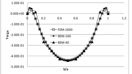
Fig 8. Equivalent shear force Vn along the side of the plate The next example is that of the previous plate now simply supported on the boundary. The corner reaction obtained with FEM for a mesh of 10000 rectangular elements is Rc = 0.0641ga and the one obtained with the BEM is Rc =
0.0642ga. Fig.(9) shows the distribution of the equivalent
shear force along the side of the plate.
VII. CONCLUSIONS
In this paper, a study was presented of the boundary
‐0.45
‐0.4
‐0.35
‐0.3
‐0.25
‐0.2
‐0.15
‐0.1
‐0.05 0
0 0.2 0.4 0.6 0.8 1
Vn
/g
a
S/a FEM‐1600
[image:6.595.46.261.317.479.2]BEM 40
Fig 9 Equivalent shear force Vn along the side of the plate simply supported on the boundary
shown that in some plate corners, the equivalent shear force Vn and bending moment mn are equal to zero. It has been
demonstrated that the corner reaction only exists in corners whose sides are simply supported and whose angle is π/2 or 3π/2 . In the presented examples, the results obtained with this formulation with coarse meshes showed an excellent agreement with those obtained from FEM with well-refined meshes
REFERENCES
[1] Jaswon, M.A.; M. Maiti, M.; Symm, G.T. Numerical biharmonic analysis and some applications. Int. J. Solids Structures, 3: 309-332, 1967
[2] Hansen, E.B. Numerical solution of integro-differential and singular integral equations for plate bending problems. Journal of Elasticity, 6 (1): 39-56, Jan. 1976
[3] Stern, M., "A general boundary integral formulations for the numerical solution of plate bending problems", Int. J. Sol. Struct., Vol. 15, pp. 769-782, 1979.
[4] Bezine, G.P. Boundary integral formulation for plate flexure with arbitrary boundary conditions. Mechanics Research Communications, 5 (4): 197-206, 1978
[5] Bezine, G. A boundary integral equation method for plate flexure with conditions inside the domain. Int. J. for Numerical Methods in Engineering, 17: 1647-1657, 1981
[6] Oliveira Neto, L. & Paiva, J.B. Cubic approximation for the transverse displacement in BEM for elastic plates analysis ,
Engineering Analysis with Boundary Elements, v.28, p.869-880,
2004. (ISSN:0955-7997)
[7] Oliveira Neto, L. & Paiva, J.B. A special BEM for elastostatic analysis of building floor slabs on columns. Computers & Structures,
v.81, n.6, p.359-372, March, 2003. (ISSN: 0045-7949)
[8] Paiva, J.B.& Mendonça, A. V. A coupled boundary
element/differential equation method formulation for plate beam interaction analysis. Engineering Analysis with Boundary Elements v. 34, p. 456-462, 2010.
[9] Paiva, J.B.; Aliabadi, M. H. . Bending moments at interfaces of thin zoned plates with discrete thickness by the boundary element method. Engineering Analysis with Boundary Elements, UK, v. 28, p. 747-751, 2004.
[10] Paiva J.B. & Venturini, W.S., "Boundary element algorithm for building floor slab analysis", Boundary Element Technology Conference, Adelaide (Austr.). Nov., 1985.
[11] Paiva, J.B. & Venturini, W.S., "Analysis of building structures considering plate-beam-column interactions", International Conference on Boundary Element Technology, Rio de Janeiro, June, 1987.
[12] Marcus,H. Die Theorie elastischer Gewebe und ihre Anwendung auf die Berechnung biegsamer Platten, Springer-Verlag Berlin and Heidelberg GmbH and Co. KG (1932), Berlin, Pg42
[image:6.595.46.275.507.635.2]