Sampling Systems. III/Flavours: Gas Chromatography.
Appendix 2: Essential Guides to Method Development in Gas Chromatography.
Further Reading
Hutte RS (1995) The sulfur chemiluminescence detector. In Adlard ER (ed.) Chromatography in Petroleum In-dustry, Amsterdam: Elsevier.
Hutte RS, Johansen NG and Legier MF (1990) Column selection and optimization for sulfur compounds analy-sis by gas chromatography.Journal of High Resolution Chromatography13: 421}426.
Karchmer JH (1970)The Analytical Chemistry of Sulphur and its Compounds, Part I. New York: John Wiley & Sons Inc.
Karchmer JH (1972)The Analytical Chemistry of Sulphur and its Compounds, Part II. New York: John Wiley & Sons Inc.
MoKssner SG, Lopez de Alda MJ, Sander LC, Lee ML and Wise SA (1999) Gas chromatographic retention behaviour of polycyclic aromatic sulfur heterocyclic compounds (dibenzothiophenes, naphtho[b]thiophenes, benzo[b]naphthiophenes and alkyl-substituted
deriva-tives) on different derivatives of different selectivity. Journal of Chromatography841: 207}228.
Saltzman ES and Cooper WJ (1989) Biogenic Sulphur in the Environment. Washington: American Chemical Society.
Simo R (1998) Trace chromatographic analysis of dimethyl sulphoxide and related methylated sulfur compounds in natural waters. Journal of Chromatography A 807: 151}164.
Thompson M and Stanisavujevic M (1980) Gas chromato-graphy and gas chromatochromato-graphydmass spectrometry of organosulphur compounds and other labile compounds. Talanta27: 477}493.
Tibbets PJC and Large R (1988) Improvements in oilR nger-printing: GC/HR MS of sulfur heterocycles. Petroana-lysis ’87:Dev.Anal.Chem.Pet.Ind., pp. 45}57. Chi-chester: John Wiley and Sons.
Wardencki W (1998) Problems with the determination of environmental sulphur compounds by gas chromatogra-phy.Journal of Chromatography A793: 1}19. Wardencki W and Zygmunt B (1991) Gas chromatographic
sulphur-sensitive detectors in environmental analysis. Analytica Chimica Acta225, 1}13.
SUPERCRITICAL FLUID
CRYSTALLIZATION
A. S. Teja and T. Furuya, Georgia Institute
of Technology, Atlanta, GA, USA Copyright^ 2000 Academic Press
Introduction
Supercritical crystallization processes use the special properties of supercritical Suids that make these Suids particularly suitable as solvents or antisolvents. In both cases, an expansion of a solution is used to create supersaturation, which is the driving force for nucleation and growth of the solute.
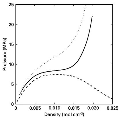
A supercriticalSuid (SCF) is aSuid above its criti-cal temperature and pressure. It is characterized by physical properties (such as viscosity and diffusivity) that can be continuously varied between those of liquids and gases. The liquid-like density of a SCF is associated with its ability to dissolve solutes, and hence its solvent power. Since this density can be changed signiRcantly by changing the pressure and temperature in the critical region, the solvent proper-ties of a supercriticalSuid can be tailored for speciRc applications. Figure 1 shows the relationship be-tween pressure and density of carbon dioxide. The region above the critical pressure and temperature
(7.38 MPa, 302.3 K) is commonly referred to as the supercritical region of carbon dioxide. It is important to note that the largest changes in the Suid density with changes in temperature and/or pressure in the single-phase region occur near the critical point. Therefore, large changes of solvent power can be achieved with small changes in pressure or temperature in the critical region. It should be added here that a supercritical crystallization process involves mixtures of solute and solvent; however, these mixtures are generally dilute so that their critical points are close to the critical point of the solvent. The behaviour depicted in Figure 1 may therefore be considered to be representative of the behaviour of dilute mixtures of constant composition.
crys-Figure 1 Pressure}density behaviour of CO2.2, 330 K;
[image:2.568.60.271.55.260.2]***, 310 K;} } } }, phase boundary.
Figure 2 Experimental apparatus for a RESS process. tals are generally free of solvent inclusions because
the solvent is likely to be in the gaseous state at the end of the expansion.
Introduction of a supercriticalSuid into an organic solvent can also result in expansion of the liquid phase, and hence, in large changes in density. If a solution containing a desired solute is expanded sufRciently by the supercritical Suid, then the liquid phase will no longer be a good solvent for the solute and nucleation will occur. In this case, the supercriti-calSuid acts as an antisolvent, and the crystallization process is known as the supercritical antisolvent (SAS) process, or by a variety of other names that are discussed below. Changes in the pressure, temper-ature, or rate of supercriticalSuid addition provide an opportunity for tailoring the SAS crystallization process for speciRc applications.
Crystallization by the Rapid Expansion
of a Supercritical Solution (RESS)
The rapid expansion of a supercritical solution (RESS) by decompression can lead to very large cha-nges in density and, hence, in the solubility of a solute in the supercritical solvent. This can result in very high supersaturation when supercritical solutions are depressurized, leading to the formation of a large number of nuclei. A typical RESS apparatus is shown
in Figure 2. Solvent is pressurized in a pump until
a pressure above its critical pressure is attained. The supercritical state is achieved by passing the pressur-ized solvent through a heat exchanger maintained at a temperature above the critical temperature of the solvent in a constant-temperature bath. The
super-critical Suid is then passed through a bed of solute where it becomes saturated with the solute. The loaded solution is then heated to a designed pre-expansion temperature, andRnally expanded quickly through an expansion device, such as a nozzle or a capillary, into a collection vessel. The expansion device is generally heated to prevent resublimation or solvent condensation. The collection vessel is main-tained at a constant temperature and pressure or vacuum, and the products are collected on a suitable substrate placed in the path of the expansion jet. The pressure in the collection vessel is ambient, but may sometimes be higher in order to control the particle size; or it may be below atmospheric to prevent con-densation of any solvent that is a liquid at ambient conditions. Variations of this equipment are possible, particularly if the solvent is to be recycled. Also, a dual RESS or DURESS process has been proposed whereby two RESS expansions are carried out in a concentric expansion device and yield, for example, a solid solute coated with a polymer.
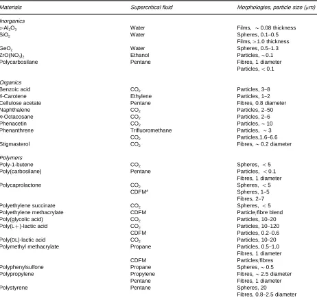
[image:2.568.299.519.584.695.2]Table 1 Substances processed using RESS
Materials Supercritical fluid Morphologies, particle size (m)
Inorganics
-Al2O3 Water Films,&0.08 thickness
SiO2 Water Spheres, 0.1}0.5
Films,'1.0 thickness
GeO2 Water Spheres, 0.5}1.3
ZrO(NO3)2 Ethanol Particles,&0.1
Polycarbosilane Pentane Fibres, 1 diameter
Particles,(0.1
Organics
Benzoic acid CO2 Particles, 3}8
-Carotene Ethylene Particles, 1}2
Cellulose acetate Pentane Fibres, 0.8 diameter
Naphthalene CO2 Particles, 2}50
n-Octacosane CO2 Particles, 2}6
Phenacetin CO2 Particles,&10
Phenanthrene Trifluoromethane Particles,&3
CO2 Particles,1.6}6.6
Stigmasterol CO2 Fibres,&0.2 diameter
Polymers
Poly-1-butene CO2 Spheres,(5
Poly(carbosilane) Pentane Particles,(0.1
Fibres, 1 diameter
Polycaprolactone CO2 Spheres,(5
CDFMa Spheres, 1
}5
Fibres, 2}7
Polyethylene succinate CO2 Spheres,(5
Polyethylene methacrylate CDFM Particle/fibre blend
Poly(glycolic acid) CO2 Particles, 10}20
Poly(L#)-lactic acid CO2 Particles, 10}120
CDFM Particles, 0.2}0.6
Poly(DL)-lactic acid CO2 Particles, 10}20
Polymethyl methacrylate Propane Particles, 0.5}1.0
Fibres, 1 diameter
CDFM Particles/fibres
Polyphenylsulfone Propane Spheres,&0.5
Polypropylene Propylene Fibres,&2.5 diameter
Pentane Fibres, 1 diameter
Polystyrene Pentane Spheres, 20
Fibres, 0.8}2.5 diameter
aCDFM, chlorodifluormethane.
formed during the expansion, solid may condense to yield a thin solidRlm.
There is a possibility ofRbre formation from super-critical solutions when an organic polymer is the solute. The polymer may form either a liquid or solid after decompression, depending on the polymer melting temperature relative to the post-expansion temperature. Fibres are generally formed when the expansion is carried out in a capillary nozzle and the post-expansion temperature is close to the melting temperature of the polymer so that the polymer de-posits as a liquid on the nozzle walls. RESS expansion of polymers yields powders when the temperature is not close to the melting temperature of the polymer. The extremely short times of product formation in
the expansion of supercritical solutions also makes it possible to produce multicomponent mixtures of powders with uniform distribution of the compo-nents. Such powders have tremendous commercial potential in the ceramic industry.
The pressure, temperature, and supersaturation proRles in and outside the expansion device determine the size of the crystals produced in the RESS process and the crystal size distribution. The pressure and temperature proRles in the expansion device can be modelled by solving the mass, energy, and momentum conservation equations for the adiabatic expansion of the supercritical Suid. Typical proRles for a capillary nozzle are shown in
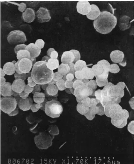
Figure 3 SEM micrographs ofn-octacosane crystals obtained in RESS expansion of a CO2solution.
[image:4.568.54.278.57.332.2]Figure 4 Density and velocity profiles in a RESS expansion of CO2 through a capillary nozzle at 443 K and 17.39 MPa.2, Velocity;} } } }, density.
Figure 6 Volumetric expansion of a ethyl acetate with CO2.
[image:4.568.296.499.485.683.2]***, 253C;} } } }, 303C;2, 403C.
Figure 5 Free jet expansion of a supercritical fluid solution from a capillary.
the device can also be modelled and is shown sche-matically in Figure 5. Calculations have shown that a Mach disc is formed a few nozzle diameters down-stream from the nozzle exit and that the pressure and temperature are very low in the region between the exit and the Mach disc. High supersaturations may therefore be obtained before, in, or after the Suid exits the nozzle and the exact proRle must be known
if control of the crystal size and crystal size distribu-tion is desired.
Crystallization by the Addition of
a Supercritical Antisolvent (SAS)
In the supercritical antisolvent (SAS) process, a press-urizedSuid is used as an antisolvent for precipitating a solid that is dissolved in a liquid solvent. The super-saturation of the solid is created by the volumetric expansion of the liquid solution. After crystallization of the solute, it is possible to remove the antisolvent completely by pressure reduction. Control of the par-ticle size distribution is also possible by manipulation of the process variables.
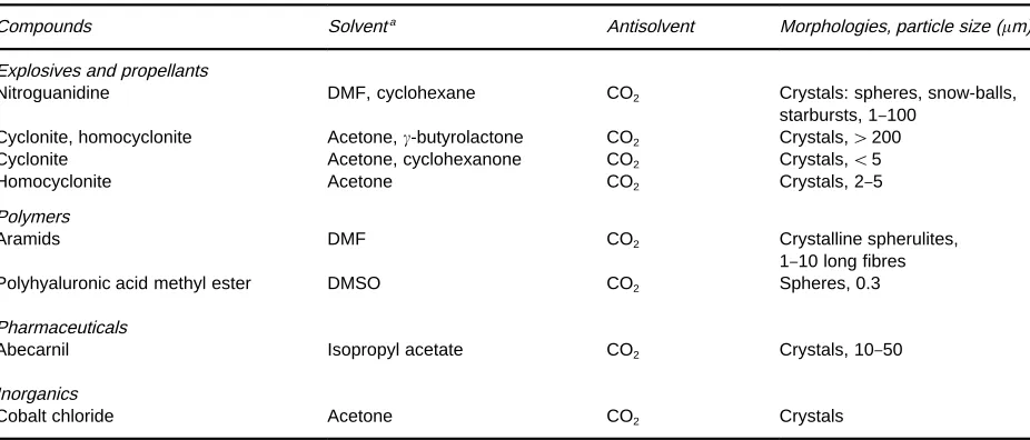
[image:4.568.61.269.501.675.2]Table 2 Substances processed using SAS with gas injection
Compounds Solventa Antisolvent Morphologies, particle size (m)
Explosives and propellants
Nitroguanidine DMF, cyclohexane CO2 Crystals: spheres, snow-balls,
starbursts, 1}100
Cyclonite, homocyclonite Acetone,-butyrolactone CO2 Crystals,'200
Cyclonite Acetone, cyclohexanone CO2 Crystals,(5
Homocyclonite Acetone CO2 Crystals, 2}5
Polymers
Aramids DMF CO2 Crystalline spherulites,
1}10 long fibres
Polyhyaluronic acid methyl ester
Pharmaceuticals
DMSO CO2 Spheres, 0.3
Abecarnil Isopropyl acetate CO2 Crystals, 10}50
Inorganics
Cobalt chloride Acetone CO2 Crystals
[image:5.568.53.516.500.698.2]aDMF, Dimethylformamide; DMSO, Dimethyl sulfoxide. Figure 7 Experimental apparatus for a batch SAS process.
thisRgure,V(%) is deRned as follows:
V(%)"100V(p,T)!V0/V0 [1]
whereV(p,T) is the volume of the liquid phase when loaded with antisolvent, andV0is the volume of the
pure liquid phase at atmospheric conditions. This expansion is large near the critical temperature of the antisolvent.
The following requirements must be satisRed for a successful SAS process: the solute must be soluble in the organic solvent at ambient temperatures and in-soluble (or sparingly in-soluble) in the SCF antisolvent. The organic solvent must be at least partially miscible with the SCF antisolvent as described above. Many organic solids satisfy these requirements, although this is not true of inorganic compounds. Inorganic compounds are generally soluble in water or acids such as sulfuric acid, but these solvents do not expand appreciably when contacted with simple gases such as
CO2 or light hydrocarbons. However, many cobalt,
nickel iron and chromium salts are soluble in acetone, cyclohexane orN-methylpyrrolidone, and these sol-vents have been used to develop SAS recrystallization processes.
The SAS process may involve antisolvent injection into a liquid phase (gas injection) or liquid solution injection into a SCF antisolvent (liquid injection) op-eration. Both these processes can be operated con-tinuously or in batch mode.
A typical experimental apparatus for batch opera-tions is shown inFigure 7. In the case of gas injection, a vessel is loaded with a known quantity of liquid solution containing the dissolved solute, and then the SCF antisolvent is added to the solution from the top or bottom of the vessel. This causes the liquid phase to expand and the solute to precipitate. The rate of antisolvent addition is an important parameter for the control of morphology and size of the solid par-ticles obtained in this process. Rapid addition of the antisolvent generally leads to smaller and more uni-form particles. Slower addition of the SCF can result in a range of particle sizes. The morphology of the particles can also be controlled by the rate of anti-solvent addition, and by the organic anti-solvent used to dissolve the solute. Examples of particles precipitated in gas injection operations are summarized in
Table 2.
Figure 8 Experimental apparatus for a continuous liquid injection SAS process.
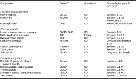
Table 3 Substances processed using SAS with liquid injection
Compounds Solventa Antisolvent Morphologies, particle
size (m)
Polymers and biopolymers
Poly (L-lactide) CH2Cl2 CO2 Spheres, 1}10
Polystyrene Toluene CO2 Spheres, 0.1}20
Microballoons
Polyacrylonitrile DMF CO2 Microfibrils, hollow fibres
Pharmaceuticals
Insulin, catalase, trypsin, lysozyme DMSO, DMF CO2 Spheres, 1}5
Methylprednisolone acetate THF Ethane Crystals, 2.5}8.5
Hydrocortisone acetate DMF CO2 Crystals, 2.5}8.5
Salmeterol xinafoate Acetone CO2 Crystalline modification,
1}10
Sodium cromoglycate Methanol CO2 Spheres, 0.1}20
Tetracycline NMP CO2 Spheres, 0.15}0.6
Salbutamol DMSO CO2 Long rods, 1}3 length
Catalysts, inorganics Red lake C, pigment yellow 1,
pigment Blue 15
Acetone CO2 Spheres,'0.6
Barium acetate, copper acetate DMSO CO2 Spheres, 0.1}0.4
Yttrium acetate DMSO CO2 Spheres, 0.1}0.3
Samarium acetate, neodymium acetate DMSO CO2 Spheres, 0.1}0.3
Zinc acetate DMSO CO2 Spheres, 0.05}0.02
aDMF, dimethylformamide; DMSO, dimethyl sulfoxide; THF, tetrahydrofuran; NMP,N-methyl-2-pyrrolidone. precipitation vessel in an apparatus similar to that
shown in Figure 8. In this operation, solids precipi-tate continuously in the vessel, as the gas phase (SCF) leaves through a pressure-control valve. The valve also maintains the pressure inside the vessel constant. The ratio of the two Sow rates (Sow rate of the liquid solution and that of the SCF antisolvent), and the type of contact (co-current or countercurrent) can be important in the evolution of the precipitation process. Continuous precipitation using liquid injec-tion has been given various acronyms such as precipi-tation by compressed antisolvent (PCA), aerosol solvent extraction system (ASES) and solution
en-hanced dispersion by supercritical (SEDS) Suid pro-cess. These processes have been carried out using slightly different precipitation procedures and in slightly different apparatus. At the end of the precipi-tation procedure, the vessel is washed with antiso-lvent to remove the liquid. This washing procedure is necessary because any liquid solvent remaining after depressurization could redissolve the solute.
Examples of solutes precipitated using liquid injec-tion are summarized inTable 3. These examples in-clude polymer microspheres, where the temperature of the precipitation vessel and the concentration of polymer in the solution play an important role in determining the morphology. There is a tendency for the polymer particles to agglomerate when the perature is higher than the glass transition tem-perature of the polymer. Also, a high polymer concentration in solution produces Rbres. On the other hand, micron-sized particles with a narrow size distribution can be obtained by adjusting the condi-tions of co-solvent and injection devices.
[image:6.568.50.515.427.699.2]provide heating/cooling. Filtration of the particles at high pressures also requires special equipment.
In summary, both RESS crystallization and SAS crystallization appear to be promising methods for generating supersaturation and therefore represent alternatives to conventional crystallization. Such al-ternatives may prove attractive in applications such as polymer and pharmaceutical processing, or in par-ticle design for drug delivery. It is possible to obtain a variety of morphologies and particle sizes in these processes by proper choice of conditions and expan-sion devices. However,a prioridesign of supercritical crystallization processes is not yet possible because the interaction between phase equilibria, expansion paths, and crystallization kinetics in these processes is not yet well understood.
See also: II/Crystallization: Control of Crystallizers and Dynamic Behaviour; Polymorphism.
Further Reading
Berends EM, Bruinsma OSL and van Rosmalen GM (1993) Nucleation and growth ofRne crystals from supercritical carbon dioxide.Journal of Crystal Growth128: 50}56.
Dixon DJ, Johnston KP and Bodmeir RA (1993) Polymeric materials formed by precipitation with a compressed
Suid antisolvent.AIChE Journal39: 127}139. Gallagher PM, Coffey MP, Krukonis VJ and Klasutis
N (1989) Gas anti-solvent recrystallization: new process to recrystallize compounds insoluble in supercritical
Suids. In: Johnston KP and Penninger JML (eds) Super-critical Fluid Science and Technology,ACS Symposium Series 406, pp. 334}354. Washington DC: American Chemical Society.
Griscik GJ, Rousseau RW and Teja AS (1995) Crystalliza-tion ofn-octacosane by the rapid expansion of super-critical solutions. Journal of Crystal Growth 155: 112}119.
McHugh MA and Krukonis VJ (1994)Supercritical Fluid Extraction: Principles and Practice, 2nd edn. Boston: Butterworth-Heinemann.
Palakodaty S, York P and Pritchard J (1998) Supercritical
Suid processing of materials from aqueous solution: the application of SEDS to lactose as a model substance. Pharmaceutical Research15: 1835}1843.
Reverchon E (1999) Supercritical antisolvent precipitation of micro- and nano-particles.Journal of Supercritical Fluids15: 1}21.
Tom JW and Debenedetti PB (1991) Particle formation with supercriticalSuids}a review.Journal of Aerosol Science22(5): 555}584.
SUPERCRITICAL FLUID
EXTRACTION
+
SUPERCRITICAL
FLUID CHROMATOGRAPHY
H. J. Vandenburg, Express Separations Ltd.,
Roecliffe, N. Yorkshire, UK
Copyright^ 2000 Academic Press
Introduction
The transfer of extracted analytes to a chromato-graphy column can be either ofSine or online. In ofSine analysis, the extracted analytes are collected and then an aliquot is manually transferred to the chromatography system. Online analysis is where the extracted analytes are automatically transferred to the analytical column. The intrinsic problems with ofSine collection are that sample loss and contamina-tion are possible, the process is difRcult to automate and the sample must be diluted with solvent to allow transfer, resulting in higher detection limits. Coupling extraction and chromatography minimizes many of these problems. Supercritical Suid extraction (SFE) and supercritical Suid chromatography (SFC) are ideally suited for coupling together as the most
frequently used solvent, carbon dioxide (CO2), is the
same for both techniques. In the case where pure CO2
is used, the extracted analytes can be deposited at the start of the analytical column simply by reducing the pressure, and chromatography started by increasing the pressure again. Capillary SFC (cSFC) beneRts par-ticularly from online methods. The columns are small and easily overloaded, particularly with injection sol-vent. For example, a 1-L injection occupies 0.5 m of a 50-m i.d. column. Larger injections can easily cause band broadening and peak splitting. The limita-tion of injeclimita-tion size increases the deteclimita-tion limit. A logical method of solving the intrinsic problems of ofSine collection and cSFC is to link them online.