International Journal of Science, Engineering and Technology Research (IJSETR) Volume 8, Issue 12, December 2019, ISSN: 2278 -7798
DESIGN, DEVELOPMENT, MODELING AND SIMULATION OF A PYROLYSIS REACTOR FROM WASTE MATERIALS
1*
Dolor Gregory A. and
2Edema Anthony O.
1,2Department of Mechanical of Engineering, Delta State Polytechniques, Otefe-Oghara, Delta State [email protected]
ABSTRACT
Plastics have become very important in today’s world.
Due to their light weight, durability, design flexibility, they are excessively used in industry as well as household and other fields. The demand for plastic is increasing day by day which now pose a tremendous threat to the environment. This study focuses on the design and fabrication of machine to convert plastic into oil as an effort in finding environment-friendly means of waste recycling by means of pyrolysis, this device is called a pyrolysis reactor. It is an alternative solution to increasing problem of waste disposal.
Pyrolysis keeps running without oxygen and in high temperature of around 250°C for which reactor is manufactured to give the expected temperature to the response. Pyrolysis process becomes an option of waste-to-energy technology to deliver bio-fuel to replace fossil fuel. The advantage of the pyrolysis process is its ability to handle unsort and dirty plastic.
Pyrolysis is also nontoxic or non-environmental harmful emission unlike incineration. In this investigation, plastic waste is utilized for pyrolysis to get fuel oil that has comparable physical properties as the energizes like petroleum, diesel and so on Converting waste plastics into fuel hold great promise for both the environmental and economic scenarios. The increased demand and high price for energy sources are driving efforts to convert organic compounds into useful hydrocarbon fuels. Although much of this work has focused on biomass, there are strong benefits to deriving fuels from waste plastic material. Waste plastic is abundant and its disposal creates large problems for the environment. Plastic does not break down in landfills, it is not easily recycled and degrades in quality during the recycling process, and it can produce waste ash, heavy metals, and potentially harmful gas emissions if incinerated at high temperatures. However, thermal processes can be used to convert plastics into hydrocarbon fuels such as gasoline, diesel, aviation / jet fuel, which have unlimited applications in airline industries, helicopter, heavy transportation, and electricity
generation. The method and principal of the production / process will be discussed.
INTRODUCTION
Pyrolysis is the thermal decomposition of materials at elevated temperatures in an inert atmosphere. That is, in the absence of oxygen. It involves a change in chemical composition and is irreversible. The pyrolysis reactor we designed uses plastic as the material. Plastics are one of the most commonly used materials in our daily life and offer remarkable contribution to the society. They are widely used in packaging and manufacture of products including electronic, automotive, etc. Plastics are light weight and can be simply formed. They show non-corrosive behaviour. They are reusable and conserve natural resources. https://en.wikipedia.org › wiki › Pyrolysis;
SCPrabhu et. al. (2019); Abhishek et. al. (2019) Plastics have high molecular mass. They are synthetic organic materials produced by polymerization. Pyrolysis involves the heating and degradation of the polymeric materials at temperatures between 250°C and 350°C without oxygen bringing about the arrangement of a carbonized singe (strong deposits) and an unpredictable division which might be isolated into condensable hydrocarbon oil and a non-condensable high caloric esteem gas. The types of plastics and their composition will condition the conversion process and will determine the pre-treatment requirements, the combustion temperature for the conversion and therefore the energy consumption required, the fuel quality output, the flue gas composition (e.g. formation of hazardous flue gases such as NOx and HO), the fly ash and bottom ash composition, and the potential of chemical corrosion of the equipment. Major factors to be considered while selection are; Smooth feeding for equipment, Effective conversion and Well-controlled combustion.
Abhishek et. al. (2019)
All Rights Reserved © 2019 IJSETR
502
Scheirs and Kaminsky, (2006) expressed that gasesframed amid the pyrolysis of natural material incorporate carbon monoxide, hydrogen, methane, carbon dioxide, water, and hydrocarbons, similar to ethane, ethane, propane, propane, butane, and so forth. The temperature and heating rates can be controlled to produce desired solid, gas and liquid products because they have considerable influence in the pyrolysis process. Yin have considered pyrolysis of waste plastic as one of the most feasible large- scale methods of energy regeneration. This is because waste plastic is a valuable source of liquid and gas fuels as well as chemicals.
Mainly there are two types of plastics: thermoplastics and thermosetting plastic. If enough heat is supplied, thermoplastics can be softened and melted repeatedly.
On cooling, they are hardened, so that they can be made into new plastics products. Examples are polyethylene terephthalate, polystyrene, polyvinyl chloride etc. They are recyclable. Thermosets or thermosetting plastics can be melted and shaped only once. It is not good to repeatedly heat treat such plastics; therefore, they remain in solid state after they have been solidified. Examples are epoxy resin, phenol formaldehyde and urea formaldehyde.
1.1. Pyrolysis process
Pyrolysis is the chemical decomposition of organic substances by heating the word is originally coined from the Greek-derived elements pyro "fire" and pyrolysis "decomposition". Pyrolysis is usually the first chemical reaction that occurs in the burning of many solid organic fuels, cloth, like wood, and paper, and also of some kinds of plastic. Pyrolysis
technology is thermal degradation process in the absence of oxygen. Plastic waste is treated in a cylindrical reactor at temperature of 300ºC – 350ºC.
the plastic melts in the reactor and as it is further heated it begins to release gas in the reactor. The gas flows through pipes into a water tank where it condenses to form biofuel or fuel oil. The biofuel produced exhibits properties similar to diesel and petrol and as such can be used as an alternative to both. Nowadays plastics waste is very harmful to our nature also for human beings. Plastic is not easily decomposable its affect in fertilization, atmosphere, mainly effect on ozone layer so it is necessary to recycle these waste plastic into useful things. So we recycle this waste plastic into a useful fuel. The advantage of this process is its ability to handle unsort and dirty plastic. it is also non-toxic and no harmful emissions are released to the environment 2.0 METHODOLOGY
2.1Designrequirements or considerations
1. The reactor must be able to withstand high temperatures
2. The reactor material must have low density so that the plastic vaporizes more easily and more oil is obtained
3. The reactor must be off the sufficient size for maximum yield of biofuel
4. The moisture content of the plastics must be low to increase oil yield
5. The feed rate must be sufficient enough for maximum oil yield
6. The heating rate must be high for maximum yield
2.2Designconcept and selection
Various design concepts were selected as shown below.
International Journal of Science, Engineering and Technology Research (IJSETR) Volume 8, Issue 12, December 2019, ISSN: 2278 -7798
Figure 1: First CAD of pyrolysis reactor This was the original concept that was chosen for the
project. However, this design proved to be ineffective because after fabrication no oil could be obtained from it. We discovered that one of the reasons for this was leakages in the reactor and pipe. We observed that as we commenced the pyrolysis process there were leakages in certain areas of the reactor particularly areas that were riveted and in the pipes where the pipe was connected to elbows. We tried to
fix this by applying fillers to the areas where the leakage occurred but that proved to be ineffective.
well even though there were leakages some of the gas still flowed through the pipe into the oil collector but the gas did not condense. All our efforts to fix this proved to be in vain hence, we decided a new design
was needed.
2.3Description of selected design
Figure 2: second CAD of the pyrolysis reactor
All Rights Reserved © 2019 IJSETR
504
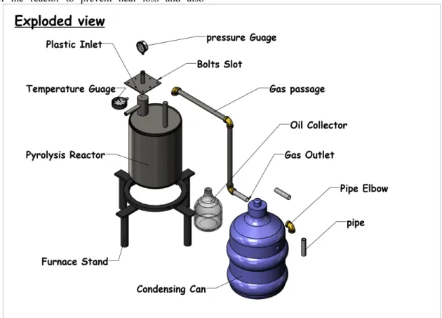
This was the next concept that was chosen wedecided to make a cylindrical vessel from a metal sheet and insert it into the metal container that we used for our last experiment. A mixture of sand, sawdust was used placed in the space between the two cylinders as a form of lagging to prevent heat loss in the reactor. The sand and saw dust mixture was mixed further with cement and used to cover the top of the reactor to prevent heat loss and also
leakage. The reactor was connected to a condensing tank using a pipe arrangement and the tank was connected to a plastic container filled with water to collect the biofuel.
2.4Designspecifications
The various parts of the reactor and their dimensions are shown below
Figure 3: exploded view of pyrolysis reactor The part dimensions are shown below
International Journal of Science, Engineering and Technology Research (IJSETR) Volume 8, Issue 12, December 2019, ISSN: 2278 -7798
Figure 4: 2D CAD of pyrolysis reactor
3.0METHODS ANDMATERIALSOF CONSTRUCTION
3.1Materials andpartsused
i. Metal sheet ii. Pressure gauge iii. Temperature gauge iv. Pipe
v. AB gum vi. Hose vii. Water viii. Heat source
ix. Hack saw x. Dispenser tank xi. Sand
xii. saw dust xiii. cement
xiv. cylindrical metal container xv. bolts and nuts
xvi. fire wood xvii. paint xviii. plastics
3.2 MATHEMATICAL MODELING Design of reactor
Reactor shell (Moss and Basic, 2013) 磨 쳌 䁠 䳌
Design of condenser Serth, (2007), Acharya et.
al. (2012)
Heat taken by m mass of solid plastics until it starts melting at Temperature, T
磨 t
Heat required to completely melt m plastics at temperature, T
磨 t Ẃ
Heat absorbed by m mass of liquid plastics until it attains a temperature of 4500C
Ẃ磨 t Ẃ
Heat required for pyrolysis
All Rights Reserved © 2019 IJSETR
506
磨 t ୗ ݍ ݅ ݕ ݕẂ ݍ ୗ ୗ ݏ
Heat transfer required
磨 ୗ ୗ ୗe ݍ ݅
t ୗ ݏ Plastic vapour production rate
磨 ୗ ୗݏ ୗ
ୗ ݏ ୗ ୗ ݍ ୗ ݏ Mass flow rate of oil vapour
t 磨Plastic vapour production rate t
Heat load in condenser
磨 t e
Mass flow rate of water,
t 磨 e 䁠
Logarithmic mean temperature difference ( 㤱 ⸱㌵
LMTD 磨 T 䁠 T ln T
T
3. 3 METHODOF CONSTRUCTION STEP I: Fabrication of the Reactor
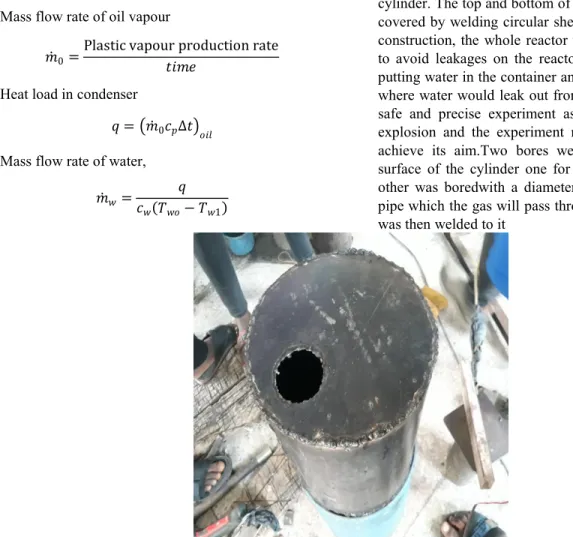
The metal sheet was rolled and welded to form a cylinder. The top and bottom of the cylinder was then covered by welding circular sheets on them.After the construction, the whole reactor was checked in order to avoid leakages on the reactor. This was done by putting water in the container and checking for points where water would leak out from. This is to ensure a safe and precise experiment as leakages can cause explosion and the experiment might not be able to achieve its aim.Two bores were made on the top surface of the cylinder one for the entrance and the other was boredwith a diameter same as that of the pipe which the gas will pass through. Before the pipe was then welded to it
Figure 5: pyrolysis reactor fabrication
STEP II: Lagging of the Reactor
After the cylinder was constructed, it was fixed into another cylinder of larger diameter. The space between the two cylinders was filled with a mixture
of sand and saw dustin order for the reactor to be lagged properly so as to reduce heat loss. The top of the reactor was also lagged with a mixture of saw dust, sand and cement.
International Journal of Science, Engineering and Technology Research (IJSETR) Volume 8, Issue 12, December 2019, ISSN: 2278 -7798
Figure 6: Pyrolysis reactor connecting fittings
STEP III: Sealing of the Entrance
The aim of the construction of the reactor is to produce oil while the plastics burn under the absence of oxygen. Since that is the case, the reactor must be air tight to avoid the flow of air (oxygen) into the
reactor while the plastics are burning. In the course of constructing the reactor, the entrance which the plastics are to enter into the reactor was ensured to be tight using nuts and bolts to tighten the input opening of the reactor. However, the plastic was loaded in the reactor before it was sealed
Figure 7: pyrolysis reactor showing sealing of entrance
STEP IV: Construction of the Condenser
The gas that evolved from the reactor via the pipe from the burning plastics was directed to the
condenser. The condenser was constructed by boring two adjacent holes on opposite surfaces on the plastic dispenser tank. Two hoses were connected to the to both holes on the condenser; one connecting the condenser to the reactor and the other connecting the condenser tank to the collecting container
All Rights Reserved © 2019 IJSETR
508
Figure 8: condenser constructionSTEP V: Operation
The pyrolysis process was started. The reactor was placed in a firewood arrangement and heated up. At about 320°C gas began to form from the plastic the gas flowed through the pipe into the condenser and
then it flowed into the collecting tank where it formed the bio oil. The entire process took about 3 hours. The oil we obtained is shown below. This oil showed the properties of a normal fuel in that it combusts just a normal fuel does.
Figure 9: pyrolysis oil RESULTS: Figures 1 to 8 show the design and
development. Figure 9 shows the produced pyrolysis oil and the combustible properties of the oil.
International Journal of Science, Engineering and Technology Research (IJSETR) Volume 8, Issue 12, December 2019, ISSN: 2278 -7798
Figure 10: reactor showing simulation results
A simulation is an approximate imitation of the operation of a process or system. Sokolowski and Banks,(2009). Therefore figure 10 shows an
approximation of the process of waste pyrolysis reactor and how the oil is produced from the reactor.
Figure 11: Max. Von mises stress analysis on the pyrolysis reactor
All Rights Reserved © 2019 IJSETR
510
The material is said to start yielding when the vonMises stress reaches a value known as yield strength, The von Mises stress is used to predict yielding of materials under complex loading from the results of uniaxial tensile tests. The von Mises stress satisfies the property where two stress states with equal distortion energy have an equal von Mises stress.
Because the von Mises yield criterion is independent
of the first stress invariant, , it is applicable for the analysis of plastic deformation for ductile materials such as metals, as onset of yield for these materials does not depend on the hydrostatic component of the stress tensor. Figure 12 is a depiction of the von mises stress analysis.
4.0 CONCLUSION AND RECOMMENDATIONS
Plastic bears a major threat to the current scenario and the environment. Millions of tonnes of plastics are produced on the daily basis and only few percentage of the waste plastic are being successfully recycled. Since, plastic takes long years to decompose, some alternative to plastic should be developed.
Also, the world is facing the problem of shortage of petroleum. Therefore, conversion of waste plastic into fuel can provide a better solution to the disposal problem of waste plastic as well as act as an alternative to fossil fuel. From the experiments and trials, we also found that by using pyrolysis method we were able to get recover oil from plastic. However, the output varies depending on the type of plastic used. Also, the plastic fuel showed properties similar to that of diesel fuel. Hence, we can conclude that pyrolysis of plastic into fuel can solve both the problem of plastic waste management as well as shortage of fossil fuel if plant is set up at the commercial level.
The project shows some light on the possibility of manufacturing liquid fuels which could be used as feed stock refinery for further modification or commercial use. By using this technology, we could solve the waste plastic problem and also significantly reduce the landfills-which are the cause of infertility of Agriculture land. Waste plastics can also become a very good source of energy and an alternative to fossil fuel which have caused an environment imbalance.
REFERENCES
1. Yuan, X., Converting Waste Plastics into Liquid Fuel by Pyrolysis: Developments in China, in Feedstock Recycling and Pyrolysis of Waste
Plastics, J. Scheirs and W. Kaminsky, Editors.
2006, John Wiley & Sons, Ltd: Changsha, P.R.
China.
2. Material Safety Data Sheet Polypropylene (PP) Indian Oil Corporation Ltd.
3. Ciliz, N.K., E. Ekinci, and C.E. Snape, Pyrolysis of virgin and waste polypropylene and its mixtures with waste polyethylene and polystyrene. Waste Management, 2004.
4. Aguado, J., D.P. Serrano, and J.M. Escola, Catalytic Upgrading of PlasticWastes, in Feedstock Recycling and Pyrolysis of Waste Plastics, J. Scheirs and W. Kaminsky, Editors.
2006, John Wiley & Sons, Ltd: Mostoles, Spain.
5. Williams, P.T., J. Scheirs and W. Kaminsky, Editors. 2006, John Wiley & Sons, Ltd: Leeds.
Yield and composition of gases and oils/waxes from the feedstock recycling of waste plastic, in Feedstock Recycling and pyrolysis of waste plastics,
6. MoinuddinSarker, Mohammad Mamunor Rashid and Muhammad Sadikur Rahman. International Journal of Modern Engineering Research (IJMER), Vol.2, Issue.4, July-Aug. 2012 pp- 2168-2173, ISSN: 2249-6645. Natural State Research, Inc. Department of Research and Development USA.
7. British Plastics Federation website:
http://www.bpf.co.uk/Recycling and Sustainability.
8. Preliminary study on the conversion of different waste plastics into fuel oil, Munich, GRIN Verlag, http://www.grin.com/en/ebook/206451/prelimina ry-study-on-the-conversion-of-differcnt- wastcplastics-into-ruel.
9. European Association of Plastics Recycling website:http:// www.eproplasticsrecycling.org 10. CONVERTING WASTE PLASTICS INTO A
RESOURCE (Compendium of Technologies) United Nations Environmental Programme Division of Technology, Industry and Economics International Environmental Technology Centre Osaka/Shiga, Japan.
11. Oluwafunmilayo A. Aworanti, Samuel E. Agarry, Ayobami O. Ajani. Advances in Chemical Engineering and Science, 2012 http://dx.doi.org/10.4236/aces.2012.24054
International Journal of Science, Engineering and Technology Research (IJSETR) Volume 8, Issue 12, December 2019, ISSN: 2278 -7798 12. Published Online October 2012
(http://www.SciRP.org/journal/aces)
13. A. C. Pinto, L. N. G. Lilian, J. C. R. Michelle, M.
R. Nu-bia, A. T. Ednildo, A. L. Wilson, A. de P.
P. Pedro and B. de A. Jailson, “Biodiesel: An Overview,” Journal of the Brazilian Chemical Society, Vol. 16, No. 6b, 2005.
14. K. Barnwal and M. P. Sharma, “Prospects of Biodiesel Production from Vegetable Oils in India,” Renewable and Sustainable Energy Reviews, Vol. 9, No. 4, 2005.
15. RECOUP, Recycling of Used Plastics webpage:
http://www.recoup.org/
16. Plastics Europe, Plastics the Facts 2013 - An analysis of European latest plastics production, demand and waste data, October 2013.
17. Plastics Recyclers Europe, how to boost plastics recycling and increase resource efficiency – Strategy Paper, 2012.
18. Knoblauch, A. J. (2009):- The environmental toll of plastics – Environmental Health News.
Retrieved from http://www.Environmental healthnews.org/ehs/ news/dangersof-plastic 19. D.S. Achilias, C. Roupakias, P. Megalokonomos,
A.A. Lappas and E.V. Antonakou: - Chemical recycling of plastic wastes made from polyethylene (LDPE and HDPE) and polypropylene (PP). Journal of Hazardous Materials (Impact Factor: 4.53), 2007, 149(3), 536-542.
20. Achyut K. Panda, R.K. Singh, D.K. Mishra: - pyrolysis of waste plastics to liquid fuel. A suitable method for plastic waste management and manufacture of value added product A world prospectives, 2009; 1-6: 10-11
21. Tiwari D.C., Ejaz Ahmad, Kumar Singh:- K.K.
International Journal of Chemical Research, ISSN: 0975-3699, Volume 1,Issue 2, 2009, pp- 31-36
22. Antony Raja and Advaith Mural:- Journal of Materials Science and Engineering B1 (2011) page no.86-89
23. Wenger JornAv.Venezuela 2007:- Asuncion/Paraguay Journal of Materials Science and Engineering A 5 (3-4) (2015) 178-180 doi:10.17265/2161-6213/2015.3-4.011
24. Manish Chand Sharma,NeeleshSoni:-The International Journal Of Engineering And Science (IJES),Volume-3 (54-58),2013, ISSN(e):
2319 – 1813 ISSN(p): 2319 – 180
25. Lakshmana Naik, M. S. Ganesha Prasadstudents, Mr. Sital Kumar Sah, Sandeep Chaudhary, Suraj Timilsina, Nischal Bhattarai, Design And Fabrication Of Machine To Convert Plastic Into Oil And Gaseous Fuel Production New Horizon College Of Engineering, Bengaluru branch:
Department Of Mechanical Engineering guide, Project Reference No.: 41s_B_Be_007college
26. http://engineeringscience18.blogspot.com/2017/0 4/pyrolysis-process-in-plastics.html
27. Mr. SCPrabhu, Anish A Amin, Anson Sunil Huns, Girish, Hamza Mohammed Hafeez, a study on extraction of fuel from waste plastic, Vol-5 Issue-2 2019, IJARIIE-ISSN(O)-2395-4396 27 Abhishek C R, Imad Ahamed I, Lohithkumar B N, Praveena R, Amruth M, 2019,
Waste Plastic Pyrolysis Oil alternative Fuel for an IC Engine, INTERNATIONAL
JOURNAL OF ENGINEERING RESEARCH &
TECHNOLOGY (IJERT) NCMPC – 2019 lume 7, Issue 07),
28. John Scheirs and Walter Kaminsky, (2006), Feedstock Recycling and Pyrolysis of Waste Plastics:
Converting Waste Plastics into Diesel and Other Fuels, Wiley, DOI: 10.1002/0470021543
29 Dennis R. Moss and Michael Basic. Pressure Vessel Design Manual. Butterworth-Heinemann,
4th edition, 2013.
30. Robert W. Serth. Process Heat Transfer Principles and Applications. Academic Press, 2007.
31 Krishna P. Acharya, Manoj Poudel, Rinoj
Gautam,Sharad R. Acharya, and Hari B. Darlami.
Design, Fabrication and Performance Testing of Pine Resin Processing Plant. Department of Mechanical Engineering, IOE, Pulchowk Campus, 2012.
32 Sokolowski, J.A.; Banks, C.M. (2009). Principles of Modeling and Simulation. John Wiley & Son. p. 6.
ISBN 978-0-470-28943-3.