Swarm Robotic Systems
Jan Dyre Bjerknes and Alan FT Winfield
AbstractThis paper challenges the common assumption that swarm robotic
systems are robust and scalable by default. We present an analysis based on both reliability modelling and experimental trials of a case study swarm performing team work, in which failures are deliberately induced. Our case study has been carefully chosen to represent a swarm task in which the overall desired system behaviour is an emergent property of the interactions between robots, in order that we can assess the fault tolerance of a self-organising system. Our findings show that in the presence of worst-case partially failed robots the overall system reliability quickly falls with increasing swarm size. We conclude that future large scale swarm systems will need a new approach to achieving high levels of fault tolerance.
1 Introduction
Research papers in Swarm Robotics frequently assert that swarm robotic systems are both scalable and robust. The fact that individual robots in the swarm make decisions based only on local sensing and communication is assumed to lead naturally to swarms that will scale to very large numbers of robots; the high degree of parallelism in robot swarms, which typically consist of homogeneous robots, is assumed to lead to a high level of robustness and dependability. While it may be true that robot swarms can exhibit an unusual level of tolerance to failure of individual robots, or external threats, when compared with conventionally engineered distributed systems, it is not safe to assume that scalability and robustness are automatically properties of all (or any) swarm systems. It is surprising therefore that, in the field of swarm robotics, there has been relatively little systematic study of dependability and
Bristol Robotics Laboratory, University of the West of England, Bristol, UK, e-mail: jandyre@tankeogteknikk.no; Alan.Winfield@uwe.ac.uk
fault tolerance. In previous papers we have argued for a systematic approach to engineering dependable swarms [15], and started to consider fault tolerance in robot swarms [16]. A recent paper by Christensen et al notably proposed a swarm algorithm, inspired by synchronised flashing seen in fireflies, in which failed robots can be detected and physically removed by operational robots [7]. In [10], Marino et al analyse, in simulation and real robot experiments, the tolerance to failures of a multi-robot team of border patrol robots.
In this paper we develop a reliability model for a case study swarm of robots that exhibit emergent, or self-organised, swarm taxis. After describing the swarm algorithm in Section 2, we outline the key failure modes for the case study swarm, and our experimental setup. In Section 3 we show that we can model this swarm – from a reliability perspective – as a k-out-of-N system. We then extend the k-out-of-N reliability model to take account of worst-case partial robot failures and swarm scaling properties in Section 4, introducing the new concept of swarm self-repair. Section 5 concludes the analysis with a model of reliability as a function of swarm size and hence addresses the question of scalability.
2 Case study: emergent swarm taxis
For our experimental case study we make use of a swarm of e-puck robots [11] with two swarm behaviours: flocking and swarm taxis toward a beacon. The combination means that the swarm maintains itself as a single coherent group while moving toward an infra-red (IR) beacon. The algorithm is a mod-ified version of the wireless connected swarming algorithm (theα-algorithm) developed by Nembrini et al [12, 14].
Our modified algorithm, which we refer to as the ω-algorithm, works as follows. Flocking is achieved with the well-known combination of short-range repulsion and longer-range attraction. Short-range repulsion is implemented with obstacle avoidance behaviour using the e-puck’s IR proximity sensors. Longer-range attraction (coherence) is achieved as follows. Each robot times the duration since it last made an avoidance manoeuvre and if that value exceeds a given threshold ω, the robot turns towards its estimate of the centre of the swarm; an estimate based on readings from the ring of infrared proximity sensors around the e-puck’s body. To increase the distance at which robots can sense each other, and also to enable robots to distinguish between robots and ambient infra-red, each of the robots are equipped with infra-red emitters that flash at 80 Hz. By sampling the sensors at 400 Hz and passing the data through a bandpass filter the 80 Hz flashing is reliably detected. Each robot can then estimate the direction of the local centre of the swarm based on which of its sensors detect a flashing signal from other robots. For the results obtained from hardware trials reported here we setω = 2.5 s; ω
For beacon-taxis, we implement an additional ‘beacon’ sensor on each robot. The beacon sensor is deliberately minimal, in that it is unable to detect the range and bearing of the remote beacon and has only a two-state output:
on = illuminated or off = not-illuminated. An important requirement of the beacon sensor is that it can be occluded by other robots, thus those robots that have a direct line-of-sight to the beacon will have beacon sensors illuminated, and those robots that are in the shadow of other robots will have beacon sensors not-illuminated. This means that for a typical swarm only the robots on or close to the leading edge of the swarm (with respect to the beacon) will have illuminated beacon sensors. Our experimental trials make use of the same IR sensors, that are used for short-range collision avoidance and longer-range coherence, for beacon sensing.
We then introduce a simple symmetry breaking mechanism. We set the short-range avoid sensor radius for those robots that are illuminated by the beacon to be slightly larger than the avoid sensor radius for those robots in the shadow of other robots. This simple mechanism results in a net swarm movement (taxis) toward the beacon. Note that the swarm taxis is an emer-gent property of the swarm: with a simple two-state beacon sensor a single robot cannot sense the direction of the beacon, and even with the symmetry breaking mechanism two or three robots are not enough to give rise to emer-gent swarm taxis; experimentally we find that swarm taxis requires at least five robots. This is important to our case study as we are interested in de-termining the reliability of a swarm with emergent swarm behaviours. For a detailed analysis of the swarm taxis behaviour see [5], and for implementation details and code listings see [4].
2.1 Failure modes and effects
This paper is concerned with analysis and modelling of reliability in swarm robotic systems and so we need to understand which faults, in individual robots, might seriously affect the operation of the overall swarm. We can summarise the failure modes and effects for our case study swarm as follows:
• Case 1: complete failures of individual robots.These are relatively benign,
in the sense that ‘dead’ robots simply become obstacles in the environment to be avoided by the other robots of the swarm. Completely failed robots (due, for instance, to a power failure) might have the effect of slowing down the swarm taxis toward the beacon, but – as shown later in Section 4 – this effect is marginal. The only situation in which complete failures could be critical is if they reduce the number of working robots in the swarm below the minimum number for the self-organising team work to function. This eventuality is modelled by the k-out-of-N approach in Section 3.
• Case 2: failure of a robot’s IR sensors. While highly unlikely given that
in the robot leaving the swarm and becoming lost. Such a robot would become a moving obstacle to the rest of the swarm and might – as in Case 1 above – reduce the number of robots required for team work. This situation is thus also modelled by the k-out-of-N approach in Section 3.
• Case 3: failure of a robot’s motors only.Motor failure only leaving all other
functions operational, including IR sensing and signalling, will have the potentially serious effect of causing the partially-failed robot to ‘anchor’ the swarm, impeding its taxis toward the beacon. If both motors fail the robot will be ‘live’ but stationary; if only one motor fails the robot will turn on the spot, which amounts to the same thing. Of the 3 cases this is by far the most serious, and will be analysed, and modelled, in Section 4.
2.2 Experimental trials
(a) (b)
Fig. 1 (a) Hardware trial of emergent swarm taxis using 10 e-puck robots. The swarm is moving toward the IR beacon located on the RHS of the arena. (b) An e-puck fitted with an opaque ‘skirt’ required to block IR light from passing through the transparent e-puck body. Also note the yellow ‘hat’ which provides a matrix of pins for the reflective spheres which allow the position tracking system to identify and track each robot.
[image:4.595.133.470.307.454.2]3 The k-out-of-N reliability model
The purpose of a reliability model is to enable the estimation of overall sys-tem reliability, given the (known) reliability of individual components of the system, see [8]. Reliability R is defined as the probability that the system will operate without failure, thus the unreliability (probability of failure) of the system, Pf = 1−R. In our case the overall system is the robot swarm
and its components are the individual robots of the swarm.
From a reliability modelling perspective a swarm of robots is clearly a parallel system of N components (robots). If the robots are independent, with equal probability of failure p, then the system probability of failure is clearly the product of robot probabilities of failure. Thus, for identical robots,
R= 1−pN.pcan be estimated using a classical reliability block diagram
ap-proach on the individual sub-systems of the robot. Since the individual robot does not internally employ parallelism or redundancy then its reliability will be modelled as a series system, givingpless than the worst sub-system in the robot, which is most likely to be its motor drive system. However, this sim-plistic modelling approach makes a serious and incorrect assumption, which is that the overall system remains fully operational if as few as one of its components remains operational. This is certainly not true of our case study swarm. The desired emergent swarm behaviours require the interaction of multiple robots and our swarm beacon taxis behaviour is a dramatic exam-ple: with one robot only the behaviour simply cannot emerge. It is a frequent characteristic of swarm robotic systems that the desired overall swarm be-haviours are not manifest with just one or a very small number of robots. However, the question of how many (or few) robots are needed in order to guarantee a required emergent behaviour in a particular swarm and for a particular behaviour is often not straightforward.
Thus, from a reliability perspective, we propose that the swarm must be be modelled as a k-out-of-N:G system. That is, a system ofN parallel elements which requires that at least k of these elements are operational (Good) for the overall system to function correctly. In a swarm of N robots, if more thanN−kfail, the self-organised functionality of the overall swarm will be compromised.
In a k-out-of-N:G system, the probability thatat least kout ofN robots are working at a given timet is given, from [9], by:
P(k, N, t) =
N
X
i=k
N i
(e−tλ)i(1
−e−tλ)N−i (1)
where λ = 1
M T BF. MTBF is the mean time before failure of an individual
robot.
0 100 200 300 400 500 600 700 800 900 1000 0
0.2 0.4 0.6 0.8 1
time, minutes
Reliability
0 20 40 60 80 100 120 140
0 0.2 0.4 0.6 0.8 1
distance, meters
Reliability
Fig. 2 Top: The reliability of a robot swarm modelled as a k-out-of-N system, withk= 5, swarm sizeN = 10 robots and MTBF = 480 m. Bottom: Reliability of the same swarm as a function of distance travelled, based on a measured mean swarm velocity of 12.4 cm. per min. for a swarm of 10 robots.
working in order for the emergent swarm taxis behaviour to work properly. Thus, we can model our swarm as a 5-out-of-N system. Consider now the individual robots’ MTBF. Carlson et al. tracked failure data for 13 robots by three different manufacturers over a period of two years. They found the MTBF to be eight hours [6]. Experiments with the e-pucks used in our experi-mental trials might suggest that their failure rate might be higher (because of the design of the e-puck battery connector). However, as no systematic data is available, the value reported by Carlson et al. will be used here. Fig. 2 (top) plots Eq. 1 for a swarm of ten robots, and shows that the swarm reliability starts to decline rapidly after 100 minutes of operation.
Fig. 2 (bottom) plots the reliability of the same swarm of ten robots, with the same values forkand MTBF, against the distance the swarm will travel (the emergent swarm taxis behaviour) based on a measured mean swarm velocity of 12.4 cm per minute for a swarm of 10 robots.
[image:6.595.151.445.80.322.2]been left behind, typically a smaller swarm (of at least 5 robots) will have a higher swarm taxis velocity. We now analyse these factors in more detail in order to improve the swarm reliability model.
4 Swarm self-repair
We now introduce the concept ofswarm self-repair. Consider the case-study swarm and its failure modes and effects analysis outlined above in Sect. 2.1. Our experimental trials confirm the failure modes and effects analysis of Sect. 2.1 and demonstrate that, while all failure modes have the effect of slowing down swarm progress toward the beacon, the swarm is tolerant to the simultaneous (i.e. worst case) failure of more than one robot. Furthermore, we notice two different categories of effect on the overall swarm: (i) sensor failures (Case 2) which slow down progress of the swarm, but the whole swarm reaches the beacon and (ii) motor failures (Cases 1 and 3) which hold back progress of the swarm until the swarm breaks free of the failed robots; for a detailed analysis of these results see [4]. Consider the second, and more serious category (ii), which gives rise to the notion of swarm self-repair.
0 200 400 600 800 1000 1200 0
500 1000 1500 2000 2500
Time, seconds
x Position
x Position of failed robot x Position of trailing robot
Fig. 3 Hardware trials using 10 e-puck robots: single robot complete failure Case 1, swarm self-repair time. Two robots are tracked: the failed robot and the trailing robot from the rest of the swarm. At about 250 s. a single robot on the leading edge of the swarm experiences Case 1 failure; at about 580 s. the trailing robot leaves the failed robot. In this case the failed robot is simply a static obstacle to the swarm, to be avoided as the swarm moves toward the beacon.
[image:7.595.196.406.353.518.2]0 200 400 600 800 1000 1200 1400 1600 0
500 1000 1500 2000 2500
Time, seconds
x Position
x Position of trailing robots x Position of failed robot
Fig. 4 Hardware trials using 10 e-puck robots: single robot partial failure Case 3, swarm self-repair time. Three robots are tracked: the failed robot, the trailing robot from the rest of the swarm and a third healthy robot left behind with the failed robot. At about 450 s. a single robot on the leading edge experiences Case 3 failure; at about 1150 s. the trailing robot ‘escapes’ the failed robot. Here the partially failed robot actively holds back the swarm - as outlined in Sect. 2.1 Case 3. To escape, the ‘pull’ of the swarm taxis needs to overcome the anchoring force of the failed robot. The healthy robot that is, by chance, left behind remains attracted by - and in the orbit of - the partially failed robot.
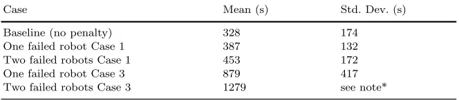
[image:8.595.195.404.96.261.2]robot(s). This is a useful metric because it varies with both the type of robot motor failure (Cases 1 or 3) and the number of robots. Table 1 lists the measured swarm self-repair times for one and two simultaneous failures for Cases 1 and 3. For comparison the table also shows a baseline notional self-repair time: the time the swarm would take to leave behind a failed robot if that robot failure did not slow down the swarm.
Table 1 Mean swarm self-repair times for the case study swarm ofN= 10 e-puck robots.
Ten runs for each case. *Here the swarm reached the beacon in only 6 of 10 runs.
Case Mean (s) Std. Dev. (s)
Baseline (no penalty) 328 174 One failed robot Case 1 387 132 Two failed robots Case 1 453 172 One failed robot Case 3 879 417 Two failed robots Case 3 1279 see note*
5 Swarm scaling and reliability
[image:8.595.134.466.487.560.2]as 5 robots. For N = 10 robots and an MTBF of 8 hours, this reliability model suggests that the swarm will become unreliable after approximately 100 minutes. While it is clear that we can increase the swarm reliability by increasing the individual robots’ MTBF, can we also make the swarm more reliable by increasing swarm size? At first it might seem plausible to suggest that the increased redundancy in a larger swarm would maintain reliability for a longer period. One may even be led to believe that the swarm could be made reliable for an arbitrarily long time, given a sufficiently large number of robots. This is not correct, and we now combine a model of swarm self-repair with the k-out-of-N model to determine the maximum upper size for our case-study swarm.
Consider the argument informally. When a swarm is larger it will take longer to self-repair than a smaller swarm. There are two reasons for this. Firstly, it is a property of our case study swarm that the swarm taxis velocity reduces with increasing swarm size. Secondly, the swarm is physically larger and must move a longer distance before it is fully self-repaired. Thus the self-repair rate willremain constantwith increased swarm size. However, for a given robot MTBF, the swarm failure-rate willincreasefor larger swarms. It is unavoidable that at some point the failure rate will overtake the self-repair rate of the swarm, and the swarm will come to a complete halt - the desired emergent swarm-taxis property will fail. In fact a swarm of sufficient size would die under it own weight, so to speak, before it has even started to move.
We now estimate the values of k and self-repair time ts as a function of
N. We will then use these values, together with the k-out-of-N model Eq. 1, to estimate swarm reliability as a function of swarm size.
5.1 The value of
k
In experimental tests it is clear that, for complete failures Case 1, two out of ten robots could fail without permanently damaging the swarm. The swarm would always self-repair. The cases with partial failure Case 3 fared less well. When one out of ten robots failed, the swarm did always self repair, even though a functioning robot might occasionally become stuck with the failed robot. But when two out of ten robots failed, the swarm would suffer a complete breakdown in four out of ten cases, and in the remaining six cases, as many as three healthy robots stayed behind with the failed robots.
Based on this the value ofkwill be conservatively estimated as 90% ofN
5.2 The value of
t
sWe know from an analysis of the scaling properties of our case study swarm [4], that swarm-taxis velocityv as a function ofN follows this relationship:
v(N) =CN−12 (2)
WhereC is a scaling constant. Thus larger swarms move more slowly. Note, as stated already, that the minimum value of swarm sizeN for the swarm to exhibit swarm taxis is 5, thus Eqn. 2 is not valid forN <5.
Clearly, the diameterd, of the swarm will increase with swarm size.
d(N) =D√N (3)
WhereD is the density constant for the swarm.
Since a robot can fail anywhere within the swarm: on the leading edge, in the middle of the swarm or at the trailing edge, the average distance that the swarm needs to move before it has moved away from the failed robot will be half the diameter, d
2. Thus the self-repair time becomests= d
2v.
Thus,
ts(N) =
D√N
2C√1
N
(4)
Which simplifies to
ts(N) =
D
2CN (5)
Eq. 5 is important as it demonstrates that the self-repair time increases linearly with N. Based on this equation it is now possible to introduce a new constant for a given swarm, namely the self-repair-time-constant. Let this constant have the symbolS for Self-repair, whereS= 2DC. Now we have
established thatSis linear withN, we can determine its value experimentally. For a swarm with ten robots with one partially failed robot the mean self-repair time was found to be 879 s (see table 1). This was for a case with ten robots, so the self-repair constant for our case study swarm, for Case 3 partial failures, then becomesS= 879
10 = 87.9.
5.3 Swarm scalability
Using the estimated values forkandtsand the k-out-of-N reliability model
we can now plot swarm reliability against swarm sizeN.
10 20 30 40 50 60 70 80 90 100 0
0.1 0.2 0.3 0.4 0.5 0.6 0.7 0.8 0.9 1
Number of robots.
Reliability
Reliability for a swarm with partially failed robots
Fig. 5 Reliability of the case study swarm as a function of swarm size, based on a k-out-of-N reliability model and assuming Case 3 partially failed robots;k= 0.9N,
self-repair-time-constantS= 87.9 and robot MTBF 8 h.
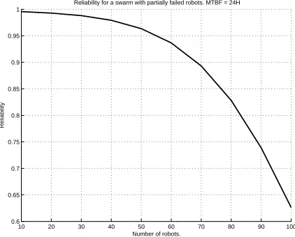
10 20 30 40 50 60 70 80 90 100 0.6
0.65 0.7 0.75 0.8 0.85 0.9 0.95 1
Number of robots.
Reliability
Reliability for a swarm with partially failed robots. MTBF = 24H
Fig. 6 Reliability of the case study swarm as a function of swarm size, based on a k-out-of-N reliability model and assuming Case 3 partially failed robots;k= 0.9N,
self-repair-time-constantS= 87.9 and robot MTBF 24 h.
[image:11.595.196.408.96.273.2] [image:11.595.195.406.322.492.2]occurs at a much lower swarm size than one might intuitively expect. Clearly we can significantly improve swarm reliability by increasing robot MTBF, as shown in Fig. 6. A four-fold increase in MTBF from 8 h to 24 h increases the swarm size with 0.9 reliability from 20 robots (Fig. 5) to 70 robots.
6 Concluding discussion
The analysis of this paper raises two questions: firstly, to what extent can our conclusions be generalised, and secondly, what measures might be needed to improve the fault tolerance of swarm robotic systems. Addressing these questions in turn:
(1) We would argue two general conclusions from this work. Firstly, that our k-out-of-N approach to reliability modelling holds true for any swarm robotic system which depends on team work, i.e. the interaction of multi-ple robots giving rise to the desired overall swarm behaviour(s). Team work contrasts with parallel work in which any single robot can complete the task on its own, but multiple robots speed up task completion (subject to the constraint of interference between robots). Secondly, it follows that scaling to larger swarm sizes requires either more reliable individual robots, or ac-tive measures to improve fault tolerance (or both). Our analysis of what we call swarm self-repair and how it impacts swarm scaling and reliability is, of course, specific to the algorithm of our case study but, we contend, should apply to any swarm system in which swarm failure rate can overtake the swarm self-repair rate, with increasing swarm size. But even if that con-tention is wrong, invoking the Popperian criterion of scientific falsification, we only need to show that the assumption of swarm robustness and scalability is false once in order to cast its general validity into doubt.
cells into multi-celled organisms), which is that such systems cannot function without an active approach to dealing with failed or rogue units, i.e. an immune response. What is perhaps surprising is that such an approach will be needed in swarm systems with relatively few individuals, i.e. less than a hundred.
References
1. Bjerknes, J.D.: Video of 10 e-puck swarm taxis trial with 2 simultaneous complete failures (2008). URL http://www.youtube.com/watch?v=zXrXCbag2iM
2. Bjerknes, J.D.: Video of 10 e-puck swarm taxis trial with 2 simultaneous partial failures (2008). URL http://www.youtube.com/watch?v=e2Zsga1pUIo
3. Bjerknes, J.D.: Video of 10 e-puck swarm taxis trial with no failures (2008). URL http://www.youtube.com/watch?v=DCyCaHePTd8
4. Bjerknes, J.D.: Scaling and fault tolerance in self-organised swarms of mobile robots. Ph.D. thesis, University of the West of England, Bristol (2010)
5. Bjerknes, J.D., Winfield, A.F.T., Melhuish, C.R.: An analysis of emergent taxis in a wireless connected swarm of mobile robots. In: Proc. IEEE Swarm Intelligence Symposium (SIS 2007), pp. 45–52 (2007)
6. Carlson, J., Murphy, R.R.: Reliability analysis of mobile robots. In: Proc. IEEE Int. Conf. on Robotics and Automation (ICRA 2003), pp. 274–281 (2003)
7. Christensen, A., O’Grady, R., Dorigo, M.: From fireflies to fault tolerant swarms of robots. IEEE Transactions on Evolutionary Computation13(4), 754–766 (2009) 8. Elsayed, E.: Reliability Engineering. Addison Wesley Longman (1996)
9. Kuo, W., Zuo, M.J.: Optimal Reliability Modeling: Principles and Applications. Wiley (2002)
10. Marino, A., Parker, L.E., Antonelli, G., Caccavale, F., Chiaverini, S.: A modular and fault-tolerant approach to multi-robot perimeter patrol. In: Proceedings of IEEE In-ternational Conference on Robotics and Biomimetics (ROBIO), pp. 735–740 (2009) 11. Mondada, F., Bonani, M., Raemy, X., Pugh, J., Cianci, C., Klaptocz, A., Magnenat, S.,
Zufferey, J.C., Floreano, D., Martinoli, A.: The e-puck, a Robot Designed for Education in Engineering. In: 9th Conference on Autonomous Robot Systems and Competitions, vol. 1, pp. 59–65. Portugal (2009)
12. Nembrini, J.: Minimalist Coherent Swarming of Wireless Networked Autonomous Mo-bile Robots. PhD Thesis, University of the West of England, Bristol, UK (2005) 13. Timmis, J., Tyrrell, A., Mokhtar, M., Ismail, A., Owens, N., Bi., R.: An artificial
immune system for robot organisms. In: P. Levi, S. Kernback (eds.) Symbiotic Multi-Robot Organisms: Reliability, Adaptability and Evolution, pp. 268–288. Springer (2010)
14. Winfield, A., Liu, W., Nembrini, J., Martinoli, A.: Modelling a wireless connected swarm of mobile robots. Swarm Intelligence2(2-4), 241–266 (2008)
15. Winfield, A.F.T., Harper, C.J., Nembrini, J.: Towards dependable swarms and a new discipline of swarm engineering. In: E. S¸ahin, W. Spears (eds.) Swarm Robotics Work-shop: State-of-the-art Survey, 3342, pp. 126–142. Springer-Verlag, Berlin Heidelberg (2005)