EXTENSION OF MODEL FOLLOWING TECHNIQUES TO SLIDING MODE
FUZZY CONTROL FOR NON LINEAR SYSTEMS
A Kumar R.K. Singh Seshachalam D, Tripathi R K, Member, IEEE
Abstract -In this paper, a new algorithm based on model following technique has been presented for a Fuzzy sliding mode control. The proposed technique enables designing of fuzzy controller based on time domain specifications and the response of the fuzzy control law can be properly shaped on a sound mathematical footing. The new fuzzy control law leads to appreciable reduction of number of fuzzy rules as compared to any other algorithm reported so far. The approach also enables stability analysis of the fuzzy control law, which is often a challenging issue in fuzzy control system design. It has been found that proposed method results in much superior tracking performance, wherein a non-linear system can be forced to track the response of a properly chosen linear mathematical model.
Index Terms-Model following, Sliding Mode, fuzzy
I. INTRODUCTION
Majority of the work reported in literature related to fuzzy logic uses error and error derivative as the input to the fuzzy controller [1-3]. These fuzzy controllers based on the conventional fuzzy techniques encounter difficulty when they are extended to higher order system. This is due to the fact that a rule base dependent either on error (e) and derivatives of the error
)
(
e
e
• •e
•L
L
grows exponentially as the order of the system grows. In case of fuzzy controller based on conventional theory, it is extremely difficult to tackle systems of order higher than two, as it is not easy to formulate rule base solely dependent on heuristics for error and error derivatives in the higher order systems.Recently techniques combining fuzzy theory with sliding mode control have shown promising results in overcoming
Manuscript received Jan 30, 2007. This work was a part of research undertaken towards Doctoral thesis in the department of Electrical Engineering at Motilal Nehru National Institute of Technology, Allahabad, India.
Wg Cdr (Dr.) Anil Kumar is an Engineer with the Indian Air Force and formerly a Ph.D. scholar at MNNIT Allahabad Phone: 01132990349 fax. 011 23013849 Email anil_tiwari_1@hotmail.com
Dr. RK Singh is an Assistant Professor at Deptt of Electrical Engineering MNNIT Allahabad. Email rksingh@mnnit.in
DS Chalam is a Ph. D. scholar at MNNIT Allahabad. Email dschalam@gmail.com
Dr. R K Tripathi is an Assistant Professor at Deptt of Electrical Engineering.
these limitation of fuzzy logic based control. Several researchers [5-9] have also reported similarity between fuzzy logic control and sliding mode control and have utilized it to design fuzzy controllers based on sliding mode theory for a class of non-linear system. Most of the work reported in the design of Sliding mode fuzzy controller use
representative functions like
( ,
σ σ
.)
, whereσ
is the expression for sliding plane which results in the number of fuzzy rules being as high as 49. Sliding mode based Fuzzy control reported [5] uses 32 rule base. In this paper a new Sliding mode fuzzy control technique has been developed, which addresses all the above listed limitations of fuzzy control design. The proposed control technique is based on model following approach [7], where in a fuzzy controller minimizes error between plant vector and the model vector. The plant is forced to follow the response of an ideal mathematical model whose response has been tailored as par time domain specifications. In this way a fuzzy controller forces the plant to follow the response of a stable, ideal mathematical system and in a way fuzzy controller adapts itself to the specified time domain specifications and thus a fuzzy controller can be designed whose response can be controlled by varying the time domain specifications of the mathematical model. This technique enables one to do away with, defining complicated cost functions as the figure of merit of the system performance. The proposed fuzzy algorithm based on Sliding mode theory results in development of fuzzy rules in a very systematic way and the control law developed can be easily extended to higher order systems. The algorithm is based on driving the state vector to the sliding surface and simultaneously forcing it to the origin of state space. In this method two fuzzy inputs are suggested. The first input measures the magnitude of the distance of the state vector from the sliding plane and the second vector is the Euclidean norm of the state vector. Since, both the inputs are treated as positive quantity unlike the earlier cases [5], the proposed technique results in significant reduction of the rule base. The stability of proposed fuzzy control based on sliding mode theory is easier to prove [10].11. MODEL FOLLOWING SLIDING MODE FUZZY CONTROL
A Model following Sliding Mode Fuzzy Control Consider an th
n
order (linear or nonlinear) system given byD
U
X
G
X
F
X
(n)=
(
)
+
(
)
+
(1)Where
[
]
T n i Tn x x x
x x
x
X = =⎢⎣⎡ − ⎥⎦⎤
•
) ( 2
1, , LL, LL
is the state vector of the system,
F
(
X
)
andG
(
X
)
are non linear, uncertain continuous and bounded function .[
]
Tn
u
u
U
=
1,
L
L
represents the input vector and D represents the unknown external disturbances assumed to be bounded. It is possible to transform a large class of general nonlinear problem into this form. The elements of the state vector X are assumed to be available for measurementSuppose that the function F(X) and G(X) can be written as the sum of nominal function and a bounded unknown uncertainty the functions can be written as
0 1
0 1
( )
( )
( ),
( )
( )
( )
( ),
( )
F
G
F X
F X
F X
F X
M
G X
G X
G X
F X
M
=
+ Δ
Δ
<
=
+ Δ
Δ
<
(2)
Where
M
F1and
M
G1 are positive constant, andrepresents the Euclidean norm It is also assumed that
det( ( ) 0
G X
0≠
These assumption ensure that system follows matching conditions, which are necessary for the invariance property to hold in SMC. The system equations can be rewritten as
W
U
X
G
X
F
X
(n)=
0(
)
+
0(
)
+
(3)where,
D
U
X
G
X
F
W
=
(
Δ
(
)
+
Δ
(
))
+
andD
≤
ρ
(4) where
ρ
a positive constantThe tracking error vector is defined as E, where
x
x
e
e
e
e
E
r
T n T
T T
−
=
=
[
,
•,
L
L
L
,
−1]
(5)where, e is a general element of Error vector E,
x
ris the rthelement of model vector Xr, . The objective is to determine a control for the nonlinear system represented by (1) so as to force the system state trajectory to track a bounded reference trajectory
X
r representing the state vector of an ideal mathematical model, in the presence of uncertainties and external disturbances. In order to reduce the error to an arbitrary small residual tracking error, in the sliding mode control this is achieved by forcing the error trajectory on to a sliding hyperplane passing through the origin. For an thn
order system, a set of sliding surfaces are defined so as to represent a sliding manifold. The objective is to maintain state trajectory onto sliding manifold given by
[
( , ) ( , ) ( , )]
0) ,
(X t = σ1 X t σ2 X t σn X t =KX=
σ LLL
(6)
Which leads to polynomial representing the hyperplane
P
=
−
1−
2 •−
−
−1 n−2−
n−1n
e
e
k
e
k
e
k
L
L
L
(7)Where
k k
1, ,...,
2k
n−1are selected such that all the roots of the corresponding polynomial P are located in the left half of the complex plane. The entire process of sliding mode control can be divided into two phases. First is the reaching phase whenσ
i(
X
,
t
)
≠
0
and sliding phase when0
)
,
(
X
t
=
iσ
. If the sliding mode exists on0
)
,
(
X
t
=
iσ
then from the theory of SMC, the behavior of system is decided by the linear differential equation given by (24) and thus the sliding manifold design. Since the choice of coefficient matrix K guarantees to satisfy the Hurwitz stability criterion, the origin in the subspace)
,
(
X
t
iσ
is asymptotically stable. Thus maintaining system states on sliding manifold is equivalent to tracking problem illustrated vide (20). In SMFC, the control problem is to force the state trajectory onto the sliding plane using a linguistic control law. However instead of choosingrepresentative functions such as
( ,
σ σ
.)
as used in [7] and in [9] two representative functions are defined as follows:
( 1)
1 2
2 2
1 1
1
n
n
k
e
k e
e
D
abs
k
k
•
−
−
⎛
+
+
⎞
⎜
⎟
=
⎜
+
+
⎟
⎝
⎠
L
LL
(8)2
2
2 (n1)
R
E
e
e
e
•
−
=
=
+
+
LL
(9)Here D represents the Euclidean distance from the representative point (RP) to the sliding plane and R represents the Euclidean Norm of the state vector i.e. distance of the RP from the origin of the state space. A linguistic rule base is now developed using these
representative functions Assigning a fuzzy set to each of the variables, fuzzy rule base is designed as stated below . Rule 1 IF R is small AND D is small Then Kfuzz small Rule 2 IF R is large AND D is small Then Kfuzz is medium
Rule 3 IF R is large AND D is large Then Kfuzz is large Here, R and D are both positive quantities and Kfuzz is the magnitude of control input. The fact that fuzzy rule base has been created by manipulating the absolute values of quantity results in appreciable reduction of rule base. The appropriate direction of control effort can be determined as par the direction of
( )
σ
. The expression for fuzzy control can thus be written as)
(
)
,
(
R
D
Sign
σ
K
It is quiet evident from the above that evaluation of control Kfuzz doesn’t require Knowledge of the bounds of uncertainty as would be the case in the development of a simple sliding mode control for the system. The inferencing method used is Mamdani and various membership function are as shown in the diagram below.
μ
0
1 Small Large
1
0
Small Medium Large
[image:3.612.309.521.123.322.2]μ
Fig. 1. Output and Input membership function respectively
III SIMULATION EXAMPLES
In order to test the performance of the proposed Model following SMFC law it is applied to the second order non linear model of an inverted pendulum [7-9] and a third order system with large uncertainty. The problems have been taken to demonstrate how the developed Fuzzy law can control an inherently unstable non-linear system and can be easily extended to higher order systems. In order to demonstrate practical feasibility of the proposed scheme the controller is developed and applied to a buck converter
A. Inverted Pendulum
In the first case consider an inverted pendulum whose non linear model is given as an illustrative example [8]. This problem is representative of a rocket from a launch pad. As shown in Fig. 5, a movable pole is joined with a vehicle by a pivot. The pole, which serves as an inverted pendulum, can be kept standing by moving the vehicle appropriately. The control objective is to keep the pole in vertically upright position starting from any initial condition. The plant dynamics is then expressed as
[image:3.612.62.269.126.185.2]
Fig. 2. Inverted pendulum: schematic diagram
w
u
x
b
x
f
x
=
+
+
•
)
(
)
(
(11) Where,1
2
x
x
x
⎡ ⎤
= ⎢ ⎥
⎣ ⎦
(12)Where,
x
1 denotes the angular displacement (in rad) of the pendulum from the vertical axis andx
2 is the angular velocity (in rad/S)1
2
x
x
θ
θ
=
=
(13)2 2
1 2 1
2 1
( ) 9.8sin( ) 0.05 sin(2 ) 2 / 3 0.1cos ( )
x
f x x x x
x
⎡ ⎤
⎢ ⎥
=⎢ − ⎥
⎢ − ⎥
⎣ ⎦
(14)
2 1
0
( )
0.1cos( 1)
2 / 3 0.1cos ( )
b x
x
x
⎡
⎤
⎢
⎥
=
⎢
−
⎥
−
⎢
⎥
⎣
⎦
(15)
2
0
w
w
⎡ ⎤
= ⎢ ⎥
⎣ ⎦
Here
w
2 is external disturbance The magnitude of disturbance is less than 1 max(w
2 )=0.1The control objective s to regulate x to 0. Selectings
=
[
1 0.2
]
for stability considerationModel- A fast model is selected with a settling time of 250mS and damping ratio of 0.8. Model dynamics can be written as.
32
400
400
X
d
X
d
Xd
r
•• •
+
+
=
(16)
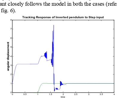
B Simulation Results Extensive simulations in Matlab were carried out to check the response of closed loop system to a reference square wave input. It is seen that plant closely follows the model in both the cases (refer fig. 5 & fig. 6).
0 0.5 1 1.5 2 2.5 3 3.5 4 0
1 2 3 4 5 6 7 8
time
a
ngu
la
r di
s
pl
a
c
e
m
e
nt
Tracking Response of Inverted pendulum to Step input
Fig 3. Tracking Response of inverted pendulum FSMC
M
sin
m g θ
l
[image:3.612.318.514.489.653.2]0 0.5 1 1.5 2 2.5 3 3.5 4 0
20 40 60 80 100 120 140 160 180
time
input
f
u
zz
y
v
a
ri
abl
e
[image:4.612.323.501.78.217.2]Variation of Input Fuzzy Variable
Fig 4. Variation of input Fuzzy variable
0 0.5 1 1.5 2 2.5 3 3.5 4
-150 -100 -50 0 50 100 150
time
c
ontr
o
l
[image:4.612.319.498.258.397.2]Control Plot
Fig. 5. Variation of Control Input
IV. PRACTICAL APPLICATION
Sliding mode fuzzy control has been successfully applied in a number of application ranging from aerospace to autonomous vehicle control [19-21]. In this section above developed algorithm is applied in the design of Sliding mode Fuzzy logic controller for a buck converter operating in CCM. It is an offline fuzzy controller where the width of the membership functions is fixed. An important claim of this paper is a drastic reduction in rule base as compared to a conventional fuzzy logic controller, where the number of rules increases exponentially with increase in input membership functions. Simulation studies are carried out using MATLAB SIMULINK, fuzzy logic toolbox, and result is compared with a conventional 7x7 rule based fuzzy controller for the same buck converter.
TABLE. 1
BUCK CONVERTER DESIGN PARAMETERS
Sl No Element value
1 Inductor 10mH 2 Capacitor 470µF 3 Input Supply Voltage 25V(nominal)
4 Load resistance 8Ω
Fuzzy Inference system type: MamdaniDefuzzification: Smallest of maximum (som)
Fig.10. Plot of Output voltage with time at RL=4Ω
Fig.11. Plot of Output voltage with time RL=8Ω to 4Ω at
0.06 sec
V CONCLUSION
In this paper a new algorithm has been developed that is based on model following Fuzzy sliding mode control. Proposed algorithm enables passing of second order time domain specifications to the fuzzy design. The performance of the controller is verified by applying it to a second order non linear model of an inverted pendulum and Simulation results have shown that the proposed scheme works better than earlier reported algorithms and results in significant reduction of the rule base.
APPENDIX Stability Analysis of Proposed scheme
In order to prove the convergence of the error by the proposed FSMC scheme, it needs to be proved that fuzzy manipulation of representative functions i.e. D and R will result in negative definiteness of a properly selected
so selected that coefficients of the polynomial meet Hurwitz stability criteria. Therefore, in order to prove the asymptotic stability of the system it is sufficient to prove that manipulation of fuzzy variable D results in negative definiteness of a properly selected Lyapunov function. This ensures convergence of error to a desired finite value.
Reproducing (1)
W
U
X
G
X
F
X
(n)=
0(
)
+
0(
)
+
, (17) the switching surfaces are defined as0
)
,
(
X
t
=
KX
=
σ
and the sliding condition is given as (18)0
)
,
(
)
,
(
≤
=
• •t
X
t
X
V
σ
Tσ
Replacing expression forn
KX
t
X
=
•)
,
(
σ
(19)}
)
(
)
(
{
)
,
(
X
t
K
F
0X
G
0X
U
W
V
=
T+
+
•
σ
(20) for simplicity of expression let
T T
t
X
σ
σ
(
,
)
=
(21)the following expression follows
KW
U
X
KG
X
KF
V
=
σ
T+
σ
T+
σ
T•
)
(
)
(
0 0 (22) For further simplicityLet
U
(
KG X
0( ))
1U
∧ −
=
be defined (23) Therefore (4.22) modifies toKW
U
X
KF
V
=
σ
T+
σ
T+
σ
T∧ •
)
(
0 (24)
since manifold is summation of individual sliding surfaces, it can be written
σ
σ
σ
σ
σ
i n i i T TT
KF
X
U
KW
V
∑
==• ∧ •
=
+
+
=
0(
)
1(25)
since
T
σ
can be expressed in terms of individual switchingsurfaces the expression can be modified as
Considering the case
KG
0(
X
)
>
0
for any X, from (26) itfollows
U
∝
U
∧
Therefore, if
σ
j >0 it follows decreasing∧
U
will ensuresliding condition
σ
Tσ
•<
0
Which will ensure asymptotic stability. In order to establish Sliding mode fuzzy control does result in above stated
manipulation of variable
∧
U
a lyapunov candidate is selected as underLet
V
=
0.5
DD
T, (28)Where, D is defined as in (8)
2 2 2
1 2 1
1
...
nV
D D
k
k
k
σ σ
•• •
−
=
=
+
+
+
(29) By algebraic manipulation
σ
σ
σ
σ
σ
i n i i T T TKW
U
X
KF
V
∑
==• ∧ •
=
+
+
=
0(
)
1(30)
or
V
1{
TKF
0(
X
)
TU
TKW
}
i n i
i
σ
σ
−
σ
+
σ
+
σ
=
== • ∧•
∑
(31)
From expression (4.29) and (4.31) it is seen that if
σ
>
0
,then
D
>
0
increasing∧
U
ensures•
V
to be negativemaking
<
0
•
σ
σ
, similarly ifσ
<
0
thenD
<
0
,decreasing
∧
U
Ensures>
0
•
σ
making<
0
•
σ
σ
fromabove relation it follows system is asymptotically stable
from it also follows
U
∝
D
∧
. Therefore manipulation of variable D as par fuzzy rule base would result in asymptotic stability of the system.
0( ) { ( )1 1 2( ) ...2 ( )}
T T
m m
V σ KF X σ u σ u σ u σ KW
•
= + + + + +
(26)
As the lumped disturbance and uncertainty follow matching conditions matrix W can be written as a product of input matrix and some matrix J
0( ) { ( )1 1 2( ) ...2 ( )} 0( )
T T
m m
V σ KF X σ u σ u σ u σ KG X J
•
= + + + + +
(27)
REFERENCES
[1] Jan Jantzen, “Design of Fuzzy Controllers”, Tech report no98-E 864 (design)
[2] Jan Jantzen, “Tuning of Fuzzy PID Controllers”, Tech report no98-E 871 (design)
[3] Chuen Chien Lee, “Fuzzy Logic in Control System: Fuzzy Logic Controller” IEEE Transaction on System Man and Cybernetics”Vol 20, No.2 Mar/Apr1990.
[4] Y. D. Landau, "Adaptive Control: The Model Reference Approach," New York, Dekker, 1979.
[5] Rainer Palm, “Robust Control by Fuzzy Sliding Mode” Automaica Vol 30 no. 9, pp1429-1437, 1994..
[6] D Drainkov, H Hellendoorn, M Reinfrank, “An Introduction to fuzzy control,” Narosa Publishing house. ISBN 81-7319-069-0 K.
[7] Okyay Kaynak, “The Fusion of Computationally Intelligent Methodologies and Sliding-Mode Control-A Survey,” IEEE Transactions on industrial electronics, Vol. 48, No. 1, Feb. 2001. [8] L. K. Wong, H. F. Leung Peter K. S. Tam, “A
Fuzzy Controller for Non Linear System”, IEEE Transaction on Industrial Electronics Vol. 48 No.1 Feb 2001.
[9] L. K. Wong, H. F. Leung Peter K. S. Tam, “An Improved Lyapunov Function Based Stability Analysis Method For Fuzzy Logic Control systems,” IEEE on line publication 0-7803-5877 Yr 2000.
[10] L. K. Wong, H. F. Leung Peter K. S. Tam, “The Design of Stable Fuzzy Logic Controllers with combination of Conventional Controllers,” IEEE on line publication catalog number 97TH 8280
[12] L. K. Wong, H. F. Leung Peter K. S. Tam, “Improved Stability Analysis Method for Fuzzy Logic Control Systems”, Electronics Letter on line No. 20000787 IEE 2000.
[13] Xinghuo yu, zhihong Mau ,“Design of fuzzy sliding mode control systems,” Trans on Fuzzy sets and system 95(1998)295-306, Elsevier publisher
[14] K. Sudhakar Shenoy and S.B. Phadke, “Design of Sliding Mode Control Using fuzzy Logic” Proceedings of Computer Society of India, pp. 205-212, 1996
[15] W.S. Lin and C.S. Chen, “Robust Adaptive Sliding Mode Control Using Fuzzy Modeling for a class of Uncertain MIMO Non Linear Systems,” IEE Proceedings Control Theory and Application Vol.149 No.3, May 2002
[16] Yu Sheng Lu and Jian, “A Self Organizing Fuzzy Sliding –Mode Controller Design For a Class of Non Linear Servo System” IEEE Transactions on Industrial Electronics, Vol. 41 No.5 Oct 1994 [17] I Eksin, M Guzelkaya and S Tokat “Self Tuning
Mechanism for Sliding Surface Slope Adjustment in Fuzzy Sliding Mode Controllers,” Proceedings Institution of Mechanical Engineers Vol. 216 Part I Journal Systems and Control Engineering 2002. [18] A. J. Healey and D. Lienard, “Multivariable Sliding
Mode Control for Autonomous Diving and Steering of Unmanned Underwater Vehicles,” IEEE Journal of Oceanic Engineering, vol. 18, No. 3, 1993. [19] Q. P. Ha, Q. H. Nguyen, and D.C. Rye, “Fuzzy
Sliding Mode Controllers with Applications” IEEE Transactions on Industrial Electronics Vol. 48. No.1 Feb 2001.
[20] S F Wu C J H Engelen Q P Chu, “Fuzzy Logic based Attitude Control Of the Space craft X-38 along a nominal reentry trajectory,” Control Engineering Practice 9 pp.699-707 2001
[21] S F Wu C J H Engelen Q P Chu, “Fuzzy Logic based full Envelope autonomous flight control for an atmospheric reentry Aircraft,” Control Engineering Practice 11 pp.11-25, 2003
[22] Han-Xiong Li and Shaocheng Tong, “A Hybrid Adaptive Fuzzy Control for a Class of Nonlinear MIMO Systems,” IEEE Transactions on Fuzzy Systems, Vol. 11, No. 1, Feb 2003.
[23] Ralph G. Berstecher, Rainer Palm, “An Adaptive Fuzzy Sliding-Mode Controller,” IEEE Transaction on Industrial Electronics, Vol. 48, No. 1, Feb 2001.