Towards Verifying Correctness of Wireless
Sensor Network Applications using Insense and
Spin
O. Sharma1, J. Lewis2, A. Miller1, A. Dearle2, D. Balasubramaniam2, R.
Morrison2, and J. Sventek1
1 Department of Computing Science, University of Glasgow, Scotland 2 School of Computer Science, University of St. Andrews, Scotland
Abstract. The design and implementation of wireless sensor network applications often require domain experts, who may lack expertise in soft-ware engineering, to produce resource-constrained, concurrent, real-time software without the support of high-level software engineering facilities. The Insense language aims to address this mismatch by allowing the complexities of synchronisation, memory management and event-driven programming to be borne by the language implementation rather than by the programmer. The main contribution of this paper is an initial step towards verifying the correctness ofWSNapplications with a focus on concurrency. We model part of the synchronisation mechanism of the Insense language implementation using Promela constructs and verify its correctness using SPIN. We demonstrate how a previously published version of the mechanism is shown to be incorrect by SPIN, and give complete verification results for the revised mechanism.
Keywords
Promela; SPIN; Concurrency; Distributed systems; Formal Modelling; Wireless Sensor Networks
1
Introduction
The coupling between software and hardware in the design and implementation of wireless sensor network (WSN) applications, driven by time, power and space constraints, often results in ad-hoc, platform specific software. Domain experts are expected to produce complex, concurrent, real-time and resource-constrained applications without the support of high-level software engineering facilities.
by the language implementation rather than by the programmer. Verifying the correctness of Insense applications requires that the language implementation be proved correct with respect to its defined semantics.
The main contribution of this paper is an initial step towards verifying the correctness of WSN applications by modelling the semantics of Insense using Promela constructs. We focus here on concurrent programming and in particular on the correctness of the Insense channel implementation. The Insense channels and some of their associated algorithms are modelled in Promela. SPINis then used to verify a set of sufficient conditions under which the Insense channel semantics are satisfied for a small number of sender and receiver components.
The remainder of this paper is structured as follows. Section 2 provides back-ground information on WSNs, Insense, and model checking. We then present the Insense channel model and its implementation in sections 3 and 4 respec-tively. Section 5 details the translation of the Insense channel implementation to Promela, develops a set of properties to verify the correctness of the imple-mentation and demonstrates how a previously published version of the channel algorithms is shown to be incorrect by SPIN. Section 6 presents complete ver-ification results for a revised set of algorithms and for previously unpublished connect and disconnect algorithms. Section 7 includes conclusions and some thoughts and directions on future work.
2
Background
2.1 Wireless Sensor Networks
WSNs, in general, and wireless environmental sensor networks, in particular, are receiving substantial research focus due to their potential importance to society [1]. By composing inexpensive, battery-powered, resource-constrained computa-tion platforms equipped with short range radios, one can assemble networks of sensors targeted at a variety of tasks – e.g. monitoring air or water pollution [13], tracking movement of autonomous entities (automobiles [17], wild animals [19]), and attentiveness to potentially disastrous natural situations (magma flows indicative of imminent volcanic eruptions [20]).
A typical application operating on aWSNsystem consists of code to: take measurements (either at regular intervals or when an application-specific event occurs), forward these measurements to one or more sink nodes, and subse-quently to communicate these measurements from the sink node(s) to a data centre. In order to design such an application, a variant of the following method-ology is used:
– A domain expert (e.g. hydrologist), using information obtained from a site visit and topological maps, determines the exact locations at which sensors should be placed (e.g. at the bends of a stream)
– A communications expert, using information obtained from a site visit, de-termines the exact location(s) at which the sink node(s) should be placed (e.g. with sufficient cellular telephony data signal strength to enable trans-port of the data back to a data centre)
– A communications expert, using information obtained from a site visit, topo-logical maps, and knowledge of radio wave propagation characteristics, then determines the number and placement of additional forwarding nodes in or-der to achieve required connectivity and redundancy
– The system operation is then simulated using realistic data flow scenarios to determine whether the design meets the connectivity, redundancy, and reliability requirements. If not, the design is iterated until the simulations indicate that the requirements are met.
Implementation of such a design takes many forms. The most common are:
– a component-based framework such as using the nesC extension to C under TinyOS [11] to construct the application;
– a more traditional OS kernel based approach such as using Protothreads for constructing the application in C under Contiki [10].
As these examples show, and as is normal for embedded systems, the application code is usually produced using a variant of the C programming language.
2.2 Insense
A fundamental design principle of Insense is that the complexity of concur-rent programming is borne by the language implementation rather than by the programmer. Thus, the language does not include low-level constructs such as processes, threads and semaphores. Instead, the unit of concurrent computation is a language construct called thecomponent. Components are stateful and pro-vide strong syntactic encapsulation whilst preventing sharing, thereby avoiding accidental race conditions.
create instances of other components and may be arranged into a Fractal pattern [5], enabling complex programs to be constructed. We envisage the future de-velopment of high-level software engineering tools which permit components to be chosen and assembled into distributed applications executing on collections of nodes.
The locus of control of an Insense component is by design akin to a single thread that never leaves the syntactic unit in which it is defined. As components and threads are defined by the same syntactic entity, each component may be safely replaced without affecting the correct execution of others with respect to threading. By contrast, in conventional thread based approaches, threads weave calls through multiple objects, often making it difficult (or at least expensive) to determine if a component can be replaced in a running program.
The topology of Insense applications may be dynamically changed by con-necting and disconcon-necting channels. Furthermore, new component instances may be dynamically created and executing component instances may be stopped. These mechanisms permit arbitrary components to be safely rewired and re-placed at runtime.
In order to decouple the application software from the operating system and hardware, Insense programs do not make operating system calls or set specific registers to read from a device. Instead, parts of the hardware are modelled as In-sense components with the appropriate channels to allow the desired interaction and are provided as part of anInsense library.
The Insense compiler is written in Java and generates C source code which is compiled using gcc and linked with the Insense library for the appropriate host operating system code. The current Insense library implementation is written for the Contiki operating system [10].
2.3 Model checking
Errors in system design are often not detected until the final testing stage when they are expensive to correct. Model checking [6–8] is a popular method that helps to find errors quickly by building small logical models of a system which can be automatically checked.
Verification of a concurrent system design by temporal logic model checking involves first specifying the behaviour of the system at an appropriate level of abstraction. The specification P is described using a high level formalism (often similar to a programming language), from which an associatedfinite state model,M(P), representing the system is derived. A requirement of the system is specified as a temporal logic property,φ.
A software tool called amodel checkerthen exhaustively searches the finite state model M(P), checking whether φ is true for the model. In Linear Time
Temporal Logic(LTL) model checking, this involves checking thatφholds for all
paths of the model. Ifφdoes not hold for some path, an error trace or
is an error in the design. In this case, either P, φ, or the system design (and
thus alsoP and possibly φ) must be modified, and re-checked. This process is
repeated until the model checker reports that φ holds in every initial state of
M(P), in which case we sayM(P) satisfiesφ, writtenM(P)|=φ.
Assuming that the specification and temporal properties have been con-structed with care, successful verification by model checking increases confidence in the system design, which can then be refined towards an implementation.
The model checker SPIN[12] allows one to reason about specifications written in the model specification language Promela.
Promela is an imperative style specification language designed for the de-scription of network protocols. In general, a Promela specification consists of a series of global variables, channel declarations and proctype(process template) declarations. Individual processes can be defined as instances of parameterised proctypes in which case they are initiated via a definedinitprocess. Properties are either specified usingassertstatements embedded in the body of a proctype (to check for unexpected reception, for example), an additionalmonitorprocess (to check global invariance properties), or viaLTLproperties.
WSNs are inherently concurrent and involve complex communication mech-anisms. Many aspects of their design would therefore benefit from the use of model checking techniques. Hitherto, the use of model checking in this domain has been largely restricted to the quantitative evaluation ofWSNprotocols [4, 15, 18].
SPIN has been used throughout the development of the WSNlanguage In-sense. In this paper we concentrate on the channel implementation. We show how even fairly simple analysis using SPIN has revealed errors in the early de-sign, and allowed for the development of robust code, that we are confident is error-free.
3
Insense Channel Model
Insense channels are typed and directional and are the only means for inter-component communication and synchronisation. A channel type consists of the direction of communication (inorout) and the type of messages that can be com-municated via the channel. All values in the language may be sent over channels of the appropriate type including channels themselves. Inter-component commu-nication is established by connecting anoutgoingchannel in one component to anincomingchannel of the same message type in another component using the connect operator. Similarly the language supports a disconnect operation that permits components to be unwired.
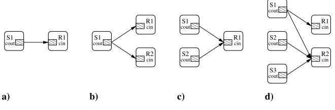
Multiple incoming and outgoing channels may be connected together enabling the specification of complex communication topologies. This facility introduces non-determinism into the send and receive operations. The semantics of send and receivecan be explained in more detail by considering Fig.1 which depicts four connection topologies.
a) b) c) d)
cout
S2
cout
R1
cin
cin
R1
cin
S1 R1
cin cout
S1
cout
S1
cout
R1
cin
R2
cin
S2
cout
S3
cout
[image:6.612.143.473.166.275.2]R2 S1
Fig. 1.Connection Topologies
4
Insense Channel Implementation
Insense channels are used for concurrency control and to provide inter-component communication via arbitrary connection topologies. Furthermore, the language is intended to permit components to be rewired and even replaced at runtime. The combination of component and channel abstractions reduces the complexity faced by the Insense programmer at the cost of increasing complexity in the channel implementation.
Each Insense channel is represented by a half channel object in the imple-mentation. Each half channel contains five fields:
1. abufferfor storing data of the corresponding message type;
2. a field called readywhich indicates if its owner is ready to send or receive data,
3. a list of pointers, calledconnections, to the channels to which the channel is connected; and
4. two binary semaphores: one calledmutexwhich serialises access to the chan-nel and,
5. another called blockedupon which the components may block.
When a channel is declared in the language a corresponding half channel is created in the implementation. Whenever a connection is made between an outgoing and an incoming channel in Insense, each half channel is locked in turn using the mutex. Next a pointer to the corresponding half channel is added to each of the connections lists and the mutex released. Disconnection is similar with theconnectionslist being traversed and the bi-directional linkage between the half channels dissolved.
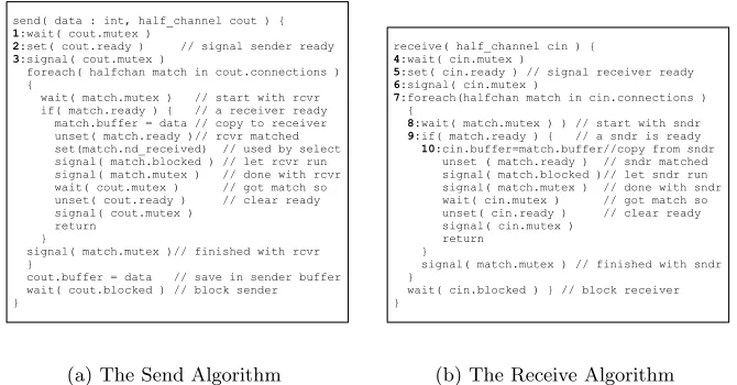
The implementation of thesend andreceive operations are shown in Fig. 2 and were published in [9]. Numbers on the left hand side of the descriptions should be ignored - they are used for reasoning purposes in Section 5.2.
Thesendandreceive operations are almost symmetric. Both operations at-tempt to find a waiting component in the list of connections with the receiver looking for a waiting sender and vice-versa. If no such match is found the sender or receiver block on the blocked semaphore until they are re-awakened by the
signal(match.blocked)statement in the corresponding receive or send
opera-tion respectively.
5
Verification of the Send and Receive Operations
send( data : int, half_channel cout ) { 1:wait( cout.mutex )
2:set( cout.ready ) // signal sender ready 3:signal( cout.mutex )
foreach( halfchan match in cout.connections ) {
wait( match.mutex ) // start with rcvr if( match.ready ) { // a receiver ready match.buffer = data // copy to receiver unset( match.ready )// rcvr matched set(match.nd_received) // used by select signal( match.blocked ) // let rcvr run signal( match.mutex ) // done with rcvr wait( cout.mutex ) // got match so unset( cout.ready ) // clear ready signal( cout.mutex )
return }
signal( match.mutex )// finished with rcvr }
cout.buffer = data // save in sender buffer wait( cout.blocked ) // block sender }
(a) The Send Algorithm
receive( half_channel cin ) {
4:wait( cin.mutex )
5:set( cin.ready ) // signal receiver ready
6:signal( cin.mutex )
7:foreach(halfchan match in cin.connections ) {
8:wait( match.mutex ) ) // start with sndr 9:if( match.ready ) { // a sndr is ready 10:cin.buffer=match.buffer//copy from sndr unset ( match.ready ) // sndr matched signal( match.blocked )// let sndr run signal( match.mutex ) // done with sndr wait( cin.mutex ) // got match so unset( cin.ready ) // clear ready signal( cin.mutex )
return }
signal( match.mutex ) // finished with sndr }
wait( cin.blocked ) } // block receiver }
[image:8.612.142.477.81.256.2](b) The Receive Algorithm
Fig. 2.Original Send and Receive Algorithms
5.1 Send and Receive in Promela
Communication between Insense components over a channel is achieved by a send operation in one component and a correspondingreceive operation in the other. We therefore model the operations in Promela using a Sender and a Receiver proctype (see Section 2.3). We can then verify the behaviour of the send/receiveoperations to/from given sets of components by initiating the appro-priate Sender/Receiverprocesses within an initprocess (see Section 2.3). Both proctypes have an associatedmyChan parameter, which is a byte identifying a process’s half-channel. In addition the Sender proctype has a data parameter indicating the item of data to be sent. After initialisation we are not interested in the actual data sent, so a single value for eachSender process suffices.
Half-channels Half-channels are implemented as C structs in the Insense im-plementation. They contain a buffer for storing an item of the channel type, semaphores and flags, and a list of other half-channels that this half-channel is connected to (see Section 4).
In Promela, we implement half-channels using variations of the following typedef definition:
typedef halfchan { // Binary semaphores
bit mutex; // locks access to channel
bit ready; //TRUE if ready to send/recv // Buffer
byte buffer;
// List of connections to other half-channels bit connections[NUMHALFCHANS];
}
Every sender and receiver is owner of exactly one half-channel. In our Promela specification all half channels are stored in a globally accessible arrayhctab.
Connections and Semaphores Each channel contains a list of other half-channels to which it is connected. The connections list is an array of bits, where a value of 1 at indexiindicates that the half-channel is connected to half-channel iin thehctabarray.
TheSendandReceivealgorithms use binary semaphores to synchronize. For example, if LOCKandUNLOCKEDare constants denoting locked and unlocked
sta-tus of a semaphore andmethe half-channel parameter, then thewaitoperation
(line (1) in Figure 2(a)) is represented by the following Promela code in the Sender proctype:
atomic{
hctab[me].mutex!=LOCKED; // wait for mutex hctab[me].mutex=LOCKED //lock mutex
}
The lock can only be obtained if it is currently not in use (that is, it is currently set toUNLOCKED). If the lock is being used, the atomic sequence blocks until the lock can be obtained. The use of an atomic statement here ensures that race conditions do not occur.
Data transfer In addition to the data item being transfered from sender to receiver, global flags are set to note the type of transfer. In the case of a sin-gle sender and receiver, there are two types of data transfer: either the sender pushes the data item to the receiver, or the receiverpulls the data item from the sender. Two bit flags, pushand pull, used for verification purposes only,
are set accordingly within appropriate atomic steps.
5.2 Error in the Original Version of the Send Algorithm
After data has been pulled by the receiver, it should have the same value as that sent by the sender. Assuming that the sender always sends data with value 5, the assert statement isassert(hctab[me].buffer==5). A safety check showed
that there was an assertion violation. Close examination of the output generated by a guided simulation provided the error execution sequence for our model. The corresponding sequence in the sendand receive operations is illustrated in the algorithms given in Figs. 2(a) and 2(b), following the numbered statements from (1) to (10). Both processes obtain their own (half-channel’s) mutex lock, set theirreadyflag and release the lock. The receiver then checks that the sender is ready for data transfer (by checking itsreadyflag), then commences to pull data from the sender’s buffer. This is where the error occurs: the data item is copied although it has not been initialized by this stage.
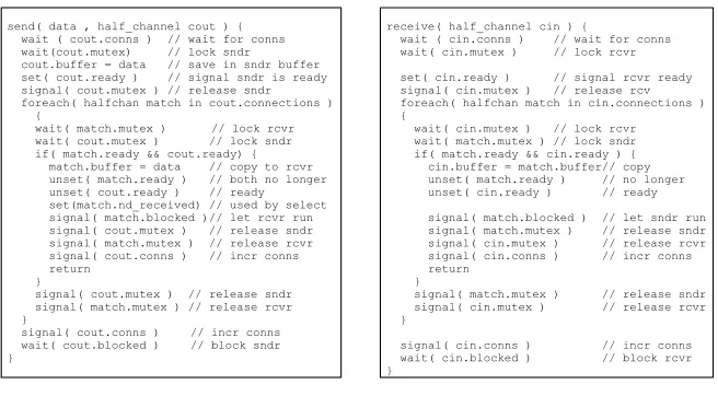
Inspection of the send algorithm shows that the sender’s buffer is not set until the penultimate line of code is reached. Possible fixes for this bug are to either set the sender’s buffer before setting the ready flag or to not set the readyflag until the buffer is initialized. To maximize parallelism, the former fix was implemented. The corrected algorithms are shown in Fig. 3. Note that in addition to the fix, aconnssemaphore, used when dynamically connecting and
disconnecting channels, is introduced to the half channel data structures and to both algorithms.
send( data , half_channel cout ) { wait ( cout.conns ) // wait for conns wait(cout.mutex) // lock sndr cout.buffer = data // save in sndr buffer set( cout.ready ) // signal sndr is ready signal( cout.mutex ) // release sndr foreach( halfchan match in cout.connections ) {
wait( match.mutex ) // lock rcvr wait( cout.mutex ) // lock sndr if( match.ready && cout.ready) { match.buffer = data // copy to rcvr unset( match.ready ) // both no longer unset( cout.ready ) // ready set(match.nd_received) // used by select signal( match.blocked )// let rcvr run signal( cout.mutex ) // release sndr signal( match.mutex ) // release rcvr signal( cout.conns ) // incr conns return
}
signal( cout.mutex ) // release sndr signal( match.mutex ) // release rcvr }
signal( cout.conns ) // incr conns wait( cout.blocked ) // block sndr }
(a) The Send Algorithm
receive( half_channel cin ) {
wait ( cin.conns ) // wait for conns wait( cin.mutex ) // lock rcvr
set( cin.ready ) // signal rcvr ready signal( cin.mutex ) // release rcv foreach( halfchan match in cin.connections ) {
wait( cin.mutex ) // lock rcvr wait( match.mutex ) // lock sndr if( match.ready && cin.ready ) { cin.buffer = match.buffer// copy unset( match.ready ) // no longer unset( cin.ready ) // ready
signal( match.blocked ) // let sndr run signal( match.mutex ) // release sndr signal( cin.mutex ) // release rcvr signal( cin.conns ) // incr conns return
}
signal( match.mutex ) // release sndr signal( cin.mutex ) // release rcvr }
signal( cin.conns ) // incr conns wait( cin.blocked ) // block rcvr }
[image:10.612.146.474.346.527.2](b) The Receive Algorithm
5.3 Extending the model for multiple processes
After adapting ourSender proctype to reflect the corrected version of thesend operation, verification runs were performed to ensure that a model with single Sender and Receiver processes behaved as expected. They were then extended to run indefinitely, via an additionalgotostatement and a label (start).
The current Promela implementation allows for multipleSenderandReceiver processes. Extra receivers require the global variableNUMHALFCHANSto be incre-mented, thereby adding an additional element to global data structures such as the half-channel table and the half-channel’s connection lists. Each receiver’s half-channel must be initialized in the initproctype and the eachsender and
receiverprocess instantiated.
With multiplesender/receiverprocesses, variables used for verification must be adapted. In particular, rather than using a single bit to indicate a sender push or receiver pull, bit arrays of length NUMHALFCHANSare used. As with the
global half-channels table, each element in these arrays is associated with a single senderor receiverprocess.
Note that some of the properties described in Section 5.4 apply only when multiplesenderorreceiverprocesses are present. In particular, property 6, which is concerned with duplication of data, applies only to versions where a sender is connected to multiple receivers.
5.4 Properties
The following list contains the high-level requirements of the channel implemen-tation provided by the Insense designers. This list was developed over a period of time during discussion between the designers and modellers. This helped to clarify the design specification.
– Property 1 In a connected system, send and receive operations are free from deadlock
– Property 2Finite progress – in a connected system data always flows from senders to receivers
– Property 3For any connection between a sender and a receiver, either the sender canpush or the receiver can pull, but not both
– Property 4Thesendoperation does not return until data has been written to a receiver’s buffer (either by sender-push or receiver-pull)
– Property 5Thereceiveoperation does not return until data has been writ-ten into its buffer (either by sender-push or receiver-pull)
– Property 6 Data passed to the send operation is written to exactly one receiver’s buffer. i.e. data is not duplicated during a singlesendoperation – Property 7 The receiver’s buffer is only written to once during a single
operation. i.e. data is never overwritten (lost) before thereceive operation returns
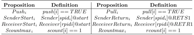
a no invalid endstates verification with SPIN, so no LTL property is required in this case. In Table 1 we define propositions used in our LTL properties to-gether with their meaning in Promela. The index i ranges from 1 to 3 and is
used to access array elements associated with theith sender orith receiver
pro-cess respectively. On the other hand, spidi and rpidi are variables storing the
process identifiers of the ith sender/receiver process respectively and are used
to remotely reference labels within a given sender/receiver process. Note that scount[i] and rcount[i] are array elements recording the number of push/pull operations executed. Variable scount[i] is incremented when the ith sender is
involved in a push or a pull, and decremented when the sender reaches itsreturn label (similarly for rcount[i]). Note that both senders and receivers can incre-ment these variables, but thescount[i]/rcount[i] variables are only decremented by the corresponding sender/receiver. The ith elements of the push and pull
[image:12.612.141.475.274.335.2]arrays record whether apushorpullhas occurredtoorfromtheith receiver.
Table 1.Propositions used inLT Lproperties
Proposition Definition Proposition Definition
P ushi push[i] ==T RU E P ulli pull[i] ==T RU E
SenderStarti Sender[spidi]@start SenderReturni Sender[spidi]@RET S1
ReceiverStartiReceiver[rpidi]@start ReceiverReturniReceiver[rpidi]@RET R1
Scountmaxi scount[i] == 1 Rcountmaxi rcount[i] == 1
We use the usual !, ||, && and → for negation, disjunction, conjunction and implication. In addition [],"#, andU denote the standard temporal
opera-tors “always”, “eventually” and “(strong) until” respectively. As shorthand we use W for “(weak) until”, where pW q denotes ([]p || (pU q)). In addition, for
1 ≤j ≤3 we use the notation [PushOrPull]j and [PushAndPull]j to represent
(P ush1||P ull1||. . .||P ushj||P ullj) and ((P ush1&&P ull1)||. . .||(P ushj&&P ullj))
respectively. Here R denotes the number of receivers. Properties are the same
for any number of Senders greater than zero.
– Property 2
• 1≤R≤3: []"#[PushOrPull]R
– Property 3
• 1≤R≤3: []![PushAndPull]R
– Property 4
• 1≤R≤3: [](SenderStart1→((!SenderReturn1)W[PushOrPull]R))
– Property 5
• 1≤R≤3: [](ReceiverStart1→((!ReceiverReturn1)W(P ush1||P ull1)))
– Property 6
• R >1: [](SenderReturn1→Scountmax1)
– Property 7
• 1≤R≤3: [](ReceiverReturn1→Rcountmax1)
6
Experimental results
The experiments were conducted on a 2.4 GHz Intel Xenon processor with 3Gb of available memory, running Linux (2.4.21) and SPIN 5.1.7.
6.1 Verification of the corrected Send and Receive operations
To provide consistency, a template model was used from which a unique model was generated for each configuration and property being tested. This allowed us to control the state-space by only including variables that were relevant to the property being tested. Promela code for our template and some example configurations, together with claim files (one per property) and full verification output for all configurations and properties can be found in an appendix at
http://www.dcs.gla.ac.uk/dias/appendices.htm.
In Table 2 we give results for scenarios in which S sender processes are
connected toR receiverprocesses, whereR+S≤4.
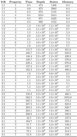
Here Property is the property number as given in Section 5.4; time is the actual verification time (user + system) in seconds;depthis the maximum search depth; states is the total number of stored states; and memory is the memory used for state storage. Compression was used throughout, and in all cases full verification was possible (with no errors).
Note that there is no result for property 6 with a single receiver, as this property applies to multiple receivers only.
6.2 Verification of the Connect/Disconnect operations
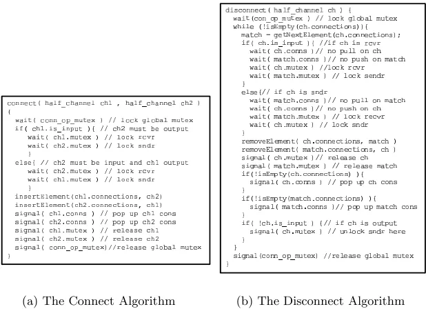
The Insense designers worked closely with the model checking experts to develop previously unpublished algorithms for dynamic connection and disconnection of components. Using SPIN, deadlocks were shown to exist in previous versions of the algorithms. The final, verified algorithms are given in Fig. 4.
We note that:
Table 2.Results for sender and receiver verifications
S:R Property Time Depth States Memory
1:1 1 0.5 474 1488 0.3
1:1 2 0.6 972 2982 0.4
1:1 3 0.5 972 1518 0.3
1:1 4 0.5 1014 2414 0.3
1:1 5 0.5 971 2425 0.3
1:1 7 0.5 969 1552 0.3
1:2 1 1.3 1.9×10⁴ 1.3
×105 4.0
1:2 2 4.3 4.1×10⁴ 2.7
×105 9.7
1:2 3 1.5 4.1×10⁴ 1.4
×105 5.3
1:2 4 2.0 4.2×10⁴ 2.0
×105 7.3
1:2 5 2.1 4.1×10⁴ 2.1
×105 7.9
1:2 6 1.5 4.0×10⁴ 1.4
×105 5.3
1:2 7 1.6 4.3×10⁴ 1.5
×105 5.7 1:3 1 115.7 1.0×10⁶ 1.1
×107 351.6 1:3 2 446.7 2.2×10⁶ 2.2
×107 832.0 1:3 3 148.4 2.2×10⁶ 1.2×10⁷ 439.3 1:3 4 188.7 2.1×10⁶ 1.5
×107 576.8 1:3 5 229.4 2.2×10⁶ 1.8×10⁷ 678.0 1:3 6 147.4 2.1×10⁶ 1.1×10⁷ 437.1 1:3 7 162.3 2.4×10⁶ 1.3×10⁷ 486.2 2:1 1 1.0 1.5×10⁴ 8.0×10⁴ 2.5 2:1 2 2.7 3.2×10⁴ 1.6×10⁵ 5.9 2:1 3 1.1 3.2×10⁴ 8.3×10⁴ 3.3 2:1 4 1.5 3.3×10⁴ 1.3×10⁵ 5.1 2:1 5 1.4 3.2×10⁴ 1.2×10⁵ 4.7
2:1 7 1.1 3.2×10⁴ 8.4
×104 3.3 2:2 1 158.2 2.3×10⁶ 1.5×10⁷ 460.1 2:2 2 562.2 5.0×10⁶ 2.8
×107 1052.0 2:2 3 205.5 5.0×10⁶ 1.6
×107 573.2 2:2 4 227.3 5.1×10⁶ 2.2
×107 828.8 2:2 5 283.3 5.0×10⁶ 2.2
×107 826.7 2:2 6 204.1 5.0×10⁶ 1.6
×107 586.1 2:2 7 209.8 5.1×10⁶ 1.6
×107 590.8 3:1 1 42.5 5.9×10⁵ 4.0
×106 127.8 3:1 2 163.7 1.2×10⁶ 7.9
×106 282.1 3:1 3 51.7 1.2×10⁶ 4.2
×106 148.3 3:1 4 83.6 1.4×10⁶ 6.8
×106 244.7 3:1 5 72.1 1.2×10⁶ 5.9
×106 214.5 3:1 7 51.9 1.2×10⁶ 4.2
(a) The Connect Algorithm (b) The Disconnect Algorithm
Fig. 4.Connect and Disconnect
– In our Promela model,R×S Connectprocesses andR+S Disconnect
pro-cesses are used to simulate connection and disconnection (1Connectprocess perSender-Receiverpair, and 1Disconnectprocess perSenderorReceiver).
The executions of these processes interleave with those ofS Sender andR
Receiverprocesses.
– As Property 2 of 5.4 refers to a connected system, it is not relevant in this context.
– All other relevant properties have been shown to hold for casesR+S ≤3.
See Table 3.
– A (further) template model was used to generate models. This template and an example model is contained in the online appendix.
7
Conclusions and Further Work
Table 3. Results for sender and receiver verifications, with additional Connect and Disconnect processes
S:R Property Time Depth States Memory
1:1 1 0.6 1.1×10³ 1.5
×104 0.7
1:1 3 0.6 2.1×10³ 1.5
×104 0.9
1:1 4 0.7 2.7×10³ 2.4
×104 1.1
1:1 5 0.7 2.1×10³ 2.4
×104 1.1 1:1 7 0.6 3.3×10³ 1.6×10⁴ 0.9 1:2 1 68.4 3.0×10⁵ 5.1×10⁶ 205.1 1:2 3 80.5 6.3×10⁵ 5.3×10⁶ 234.1 1:2 4 111.2 6.2×10⁵ 7.6×10⁶ 328.5 1:2 5 127.2 6.3×10⁵ 8.2×10⁶ 356.6 1:2 6 78.3 6.4×10⁵ 5.3×10⁶ 232.4 1:2 7 93.5 7.6×10⁵ 6.2×10⁶ 271.3 2:1 1 48.1 3.7×10⁵ 3.7×10⁶ 142.7 2:1 3 54.4 7.1×10⁵ 3.8×10⁶ 160.8 2:1 4 98.3 8.6×10⁵ 6.4×10⁶ 276.8 2:1 5 84.7 7.1×10⁵ 5.7×10⁶ 247.8 2:1 7 57.1 7.1×10⁵ 3.8×10⁶ 162.0
properties under which the channel semantics are satisfied for a small number ofsenders andreceivers.
The SPIN model checker is used to reveal errors in a previously published version of the Insense channel implementation. SPIN is also shown to aid the development of revised algorithms that are correct with respect to their defined semantics.
There are three avenues of further work in this area. First, the verification of the Insense language implementation is to be completed by modelling the non-deterministic selectoperation in Promela and using SPINto check the relevant LTLproperties.
Second, we would like to show that thesendandreceiveoperations are safe foranynumberSof senders andanynumberRof receivers. This is an example
of the parameterised model checking problem (PMCP) which is not, in general, decidable [2]. One approach that has proved successful for verifying some pa-rameterised systems involves the construction of anetwork invariant (e.g. [14]). The network invariantIrepresents an arbitrary member of a family of processes.
The problem here is especially hard, as we have two parameters,S andR. By
fixing S to be equal to 1, however, we have applied an invariant-like approach,
Finally, an important aspect of further work is to extend our methodology from verifying the Insense language implementation to verifying programs. Our intention is to model WSNapplications written in Insense using Promela con-structs and to verify correctness of these programs using SPIN.
8
Acknowledgements
This work is supported by the EPSRC grant entitled DIAS-MC (Design, Im-plementation and Adaptation of Sensor Networks through Multi-dimensional Co-design) EP/C014782/1.
References
1. I. Akyildiz, W. Su, Y. Sankarasubramaniam, and E. Cyirici. Wireless sensor net-works: A survey. Computer Networks, 38(4):393–422, 2002.
2. Krzysztof R. Apt and Dexter C. Kozen. Limits for automatic verification of finite-state concurrent systems. Information Processing Letters, 22:307–309, 1986. 3. D. Balasubramaniam, A. Dearle, and R. Morrison. A composition-based approach
to the construction and dynamic reconfiguration of wireless sensor network appli-cations. InProc. 7th Int. Symp. on Software Composition (SC 2008), volume 4954 ofLecture Notes in Computer Science, pages 206–214. Springer, 2008.
4. P. Ballarini and A. Miller. Model checking medium access control for sensor net-works. InProc. of the 2nd int’l symp. on leveraging applications of formal methods, pages 255–262. IEEE, 2006.
5. ´E. Bruneton, T. Coupaye, M. Leclercq, V. Qu´ema, and J.-B. Stefani. The fractal component model and its support in Java. Software Practice and Experience, 36(11-12):1257–1284, 2006.
6. E. Clarke and E. Emerson. Synthesis of synchronization skeletons for branching time temporal logic. InProc. of the 1st Workshop in Logic of Programs, volume 131 ofLecture Notes in Computer Science. Springer, 1981.
7. E. Clarke, E. Emerson, and A.P. Sistla. Automatic verification of finite-state con-current systems using temporal logic specifications. ACM Transactions on Pro-gramming Languages and Systems, 8(2):244–263, 1986.
8. E. Clarke, O. Grumberg, and D. Peled. Model Checking. The MIT Press, Cam-bridge, MA, 1999.
9. A. Dearle, D. Balasubramaniam, J. Lewis, and R. Morrison. A component-based model and language for wireless sensor network applications. InProc. of the 32nd Int’l Computer Software and Applications Conference (COMPSAC 2008), IEEE Computer Society, pages 1303–1308. IEEE, 2008.
10. A. Dunkels, B. Gr¨onvall, and T. Voigt. Contiki – a lightweight and flexible op-erating system for tiny networked sensors. In Proc. 1st Workshop on Embedded Networked Sensors (EmNets-I). IEEE, 2004.
11. D. Gay, P. Levis, and D. Culler. Software design patterns for TinyOS.Transactions on Embedded Computing Systems, 6(4):22, 2007.
13. A. Khan and L. Jenkins. Undersea wireless sensor network for ocean pollution prevention. In Proc. 3rd Int’l Conference on Communication Systems Software and Middleware (COMSWARE’08), IEEE, pages 2–8, 2008.
14. R. P. Kurshan and K.L. McMillan. A structural induction theorem for processes. InProceedings of the eighth Annual ACM Symposium on Principles of Distrubuted Computing, pages 239–247. ACM Press, 1989.
15. Marta Kwiatkowska, Gethin Norman, and Jeremy Sproston. Probabilistic model checking of the IEEE 802.11 wireless local area network protocol. In Proc. 2nd Joint Int’l Workshop on Process Algebra and Probabilistic Methods, Performance Modeling and Verification (PAPM-PROBMIV 2002), volume 2399 ofLecture Notes in Computer Science, pages 169–187. Springer, 2002.
16. A. Miller, M. Calder, and A.F. Donaldson. A template-based approach for the generation of abstractable and reducible models of featured networks. Computer Networks, 51(2):439–455, 2007.
17. A. Skordylis, A. Guitton, and N. Trigoni. Correlation-based data dissemination in traffic monitoring sensor networks. InProc. 2nd int’l conference on emerging networking experiments and Technoligies (CoNext’06), page 42, 2006.
18. L. Tobarra, D. Cazorla, F. Cuatero, G. Diaz, and E. Cambronero. Model checking wirelss sensor network security protocols: TinySec + LEAP. InWireless Sensor and Actor Networks, volume 248 ofIFIP International Federation for Information Processing, pages 95–106. Springer-Verlag, 2007.
19. S. Venkatraman, J. Long, K. Pister, and J. Carmena. Wireless inertial sensors for monitoring animal behaviour. In Proc. 29th Int’l Conference on Engineering in Medicine and Biology (EMBS’07), IEEE, pages 378–381, 2007.