ISSN Online: 2327-5227 ISSN Print: 2327-5219
DOI: 10.4236/jcc.2019.710011 Oct. 16, 2019 116 Journal of Computer and Communications
A Novel Iterative Detection in Downlink of
Massive MIMO System
Mingtong Sun1, Jie Wang1, Dongming Wang1, Lijun Zhai2
1National Communication Research Laboratory (NCRL), Southeast University, Nanjing, China 2CETC 54, Shijiazhuang, China
Abstract
In this paper, we propose the novel iterative detection which operates itera-tively on blocks of the received signal in downlink in massive MIMO (Mas-sive Multiple-input Multiple-output) system. This article will combine the equivalent channel with soft detection and soft decoder, and finally propose a new structure for the iterative detection in downlink based on 5G simulation test platform of NCRL and analysis the performance of the novel structure. The simulation result shows iterative algorithm performs better than conven-tional detection with lower amount of iterations.
Keywords
Iterative Algorithm, Massive MIMO, Novel Structure
1. Introduction
5G technology has grown and advanced significantly over the years through re-search and innovation. The key features of 5G contain high throughput, im-proved spectrum efficiency reduced latency, better mobility support, and high connection density. To support increased throughput requirements, massive MIMO technology is applied in 5G.
Various techniques like spatial multiplexing, diversity and precoding [1] [2] has supported to improve the channel capacity, energy efficiency, spectral effi-ciency and the reliability of the communication link. Precoding techniques used in massive MIMO system are to exploit spatial multiplexing gain or diversity gain. It is known that spatial multiplexing is used to increase the spectral effi-ciency and diversity coding is used to increase the link reliability. In [3] and [4], hybrid precoding and QR methods are introduced respectively. SVD based How to cite this paper: Sun, M.T., Wang,
J., Wang, D.M. and Zhai, L.J. (2019) A Novel Iterative Detection in Downlink of Massive MIMO System. Journal of Com-puter and Communications, 7, 116-126.
https://doi.org/10.4236/jcc.2019.710011
DOI: 10.4236/jcc.2019.710011 117 Journal of Computer and Communications
beamforming method to increase the capacity with optimum proper power allo-cation was proposed by [5] [6]. We use the two-level algorithm to decompose the multi-user MIMO channel into multiple single-user channels, which con-tains block diagonalization and SVD.
Pilot contamination and interference are well-known problems affecting communication system, requiring the need of an equalizer. Various solutions to the problem were widely investigated. The optimal, iterative equalizer applying soft feedback is LMMSE ISDIC equalizer. Iterative channel estimation and data detection is researched in [7] [8]. We consider time division duplexing since it can exploit channel reciprocity [9]. An innovated double-turbo receiver was proposed to alleviate the pilot contamination and interference, which combines the equivalent channel estimation with the detector and the decoder.
The paper is organized as follows. In Section 2, we propose the system model, including precoding algorithm, detection algorithm and so on. Section 3 intro-duces the novel detection structure and compares the proposed structure and the traditional one. Some numerical results with a performance comparison are shown in Section 4. Last, Section 5 draws the conclusions on the proposed schemes.
2. System Model
The paper considers the downlink of a MU-MIMO system. The cellular scene is a single base station serving K UEs simultaneously. Assume that the uplink and downlink has reciprocity ( T
D= U
G G ). According to [10], the following precoding scheme is used. We first calculate zero force precoding:
(
T)
1U U U 1
ˆ [ ˆ ˆ ]
K −
∗ ∗
= =
G G G G G G (1) ZF precoding forces the interference of other users to zero.
D,1
D 1
D,
ˆ ˆ ˆK
K = = G
G G G G I
G
(2)
This means
D,kˆj
k j k j = = ≠ I G G
0 (3)
MMSE precoding describes the approach which minimizes the mean square error. It does not usually eliminate ISI completely but, minimizes the total power of the noise and ISI components.
(
T 2)
1U U U 1
ˆ [ ˆ ˆ ]
t
N K K
σ −
∗ ∗
×
= + =
G G G G I G G (4)
Then make QR decomposition to Gˆk. ˆk = ˆ ˆk k
G Q R (5) where Qˆk is unitary orthogonal matrix, Rˆk is an upper triangular matrix,
DOI: 10.4236/jcc.2019.710011 118 Journal of Computer and Communications D,k ˆ ˆj j
k j k j = = ≠ I G Q R
0 (6)
ˆk
Q is the precoding matrix which satisfied the principle of BD precoding al-gorithm. We perform QR decomposition to all the Gˆk one by one, then we can
get the interference suppression matrix of downlink.
IS= ˆ1 ˆK
W Q Q (7)
The interference suppression matrix has the ability to blocks diagonalization, the specific property is as follows.
1 T
D IS U IS
K = = R
G W G W
R
(8)
where 1 T
U, IS, ˆ
k k− = k k
R R G W . It can be seen that after blocks diagonalization, the interference among multiple users is eliminated. Next, we can make SVD de-composition to matrix Rk.
H k = k k k
R U D V (9)
(
)
TT H T
k = k k k = k∗ k k
R U D V V D U (10) From (8)-(9), we can know that the downlink single-user precoding matrix is
k
V and the uplink single-user precoding matrix is Uk∗. The dimensions of
these two matrices are depended on the numbers of streams.
As for detection, [11] proposes a new low-complexity iterative detection for overloaded multiuser MIMO systems. Iterative algorithm of soft interference cancellation is researched in [12] [13] [14]. In this letter, the LMMSE-ISDIC al-gorithm is used in data detection unit. If we know the priori information of transmitted signal, the mean s and variance matrix V of transmitted signal can be calculated. If the priori information is unknown, we can set them to 0 and 1 respectively. The detection value of the kth sending symbol is
(
)
r
1
H H H H 2
k k k σ
−
= + + N −
s e s e VH HVH I r H s
(11)
From the view of downlink receiver, the received signal can be expressed as
D ISˆ
= +
y G W Vs n (12) where Vˆ and s respectively
1 ˆ ˆ ˆK = V V V
(13)
1 K = s s s
(14)
DOI: 10.4236/jcc.2019.710011 119 Journal of Computer and Communications
1 1 1 1 1
D IS
ˆ ˆ
ˆK K K ˆK K
= + = +
V s R V s
y G W n n
R
V s V s
(15)
Each user received signal is yk =R V sk k kˆ +nk. In ideal condition,
D,k IS,k′ =
G W 0 (16)
However, there are some channel estimation error in realistic scenario,
D,k IS,k′ ≠
G W 0, each user received signal is expressed as
D, IS, ˆ D, IS, ˆ
K
k k k k k k k k k
k k′≠ ′ ′ ′
= +
∑
+y G W V s G W V s n (17)
Redefining
yk =G sk k+nk (18) yk =yk (19)
k = D,k IS,k kˆ
G G W V (20)
k D, K IS,k ˆk k
k k′≠ ′ ′ ′
= k
∑
+n G W V s n (21)
( )
H K H 2k k k k
k k
σ
′ ′ ′≠
=
∑
+k E n n G G I
Ξ (22)
In ideal condition,
k =
n n (23)
( )
H 2 E k k k n n =σ IΞ (24)
Defining Ξ ,
H
H H 2 H
H 2 H
k k
k K
k k k k k k
k k k k σ σ ′ ′ ′≠ = + = + + − = + −
∑
G VGG G G G I G G
GG I G G
Ξ Ξ
(25)
So the detected symbol is as follows,
(
)
(
)
H H 1 H H 1 1 1 k kk k k k k k
k k
k k k
v − − = − + + − e G
s y G s G e s
e G G e
Ξ
Ξ (26)
where 0 j j k j k = = ≠ s
s (27)
[ ]
j j, 1j
j k v j k
= = ≠
V (28)
DOI: 10.4236/jcc.2019.710011 120 Journal of Computer and Communications
( )
E P
k
k k k k k k
∈
= =
∑
s S
s s s s s s (29)
2 2
P
k
k k
k k k
v
∈
=
∑
−s S s s s s
(30)
where S is the set of modulated symbols.
3. Receiver Structure
3.1. Traditional Receiver Structure
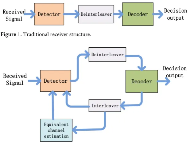
In the traditional receiver structure, there is no information interaction between the detection unit, the decoder unit and the equivalent channel unit (Figure 1).
3.2. Proposed Receiver Structure
In fact, the extra information obtained by the decoder unit can facilitate the equivalent channel unit so as to eliminate the estimation error and improve the performance of data detection. The same idea is applied between channel esti-mation and data detection in [15] [16]. The overall framework of the proposed receiver structure is as Figure 2.
3.2.1. Equivalent Channel Unit
[image:5.595.219.529.475.706.2]As Figure 2 clarifies, receiver firstly obtains the equivalent channel value at the pilot point by sending the frequency-domain pilot sequence and uses a certain interpolation algorithm to obtain initial equivalent channel value at the entire frequency point. The equivalent channel matrix is obtained by the product of the channel matrix and multi-level precoding matrix. It needs to note that the fre-quency-domain pilot sequence is the value of multi-level precoding matrix. The equivalent channel matrix is then used for detection unit.
Figure 1. Traditional receiver structure.
DOI: 10.4236/jcc.2019.710011 121 Journal of Computer and Communications
When data has already been processed by the decoder unit, the judged sym-bols can be sent back to the equivalent channel estimation unit. The channel es-timation unit can use the received signal and the reconstructed signal to re-estimate the channel matrix. The reconstructed signal is acquired by the product of the judged symbols and multi-level precoding matrix. In this paper, we use Least-Square algorithm to estimate the equivalent channel. LS algorithm is described by the following formula.
( )
H 1 HLS
− =
H s s s y (31)
where s is the reconstructed signal and y is the corresponding received se-quence.
3.2.2. Detection Unit
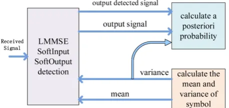
The detection unit has accepted the LMMSE-ISDIC algorithm to detect the re-ceived symbols. The LMMSE-ISDIC algorithm performs a matrix inversion op-eration in every single itop-eration. The complexity of LMMSE-ISDIC in single ite-ration is relatively low. LMMSE-ISDIC is an iterative algorithm and need to cal-culate symbolic probability, prior mean and variance (Figure 3).
3.2.3. Decoder Unit
Turbo decoder algorithm is applied in the decoder unit. In the iterative detection algorithm, the extrinsic information of decoder will be feed back to the detection unit as the priori information. As the information exchange among the detection unit, the decoder unit and the equivalent channel estimation units, the precision of the three units are enhanced simultaneously during the overall iteration process, which is similar to turbo structure.
4. Simulation
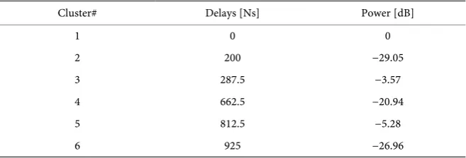
The simulation environment of this paper is similar to SCME Urban micro-cell, it has six clusters, each cluster delay and power are in Table 1.
[image:6.595.260.489.594.702.2]The paper considers one base station in one cell and the base station serves 16 UEs simultaneously, each UE with 8 antennas. Correspondingly, the base station has 128 antennas. The number of each UE’s data stream is 4. The modulation type is QPSK. Assuming that users are evenly distributed around the base sta-tion.
DOI: 10.4236/jcc.2019.710011 122 Journal of Computer and Communications
Table 1. Cluster delat and power.
Cluster# Delays [Ns] Power [dB]
1 0 0
2 200 −29.05
3 287.5 −3.57
4 662.5 −20.94
5 812.5 −5.28
6 925 −26.96
The article gives the BER (Bit Error Rate) and system achieve rate in downlink when the speed of UE is 3 km/h. The achieve rate is calculated by data blocks, each data block containing 2400 information bits.
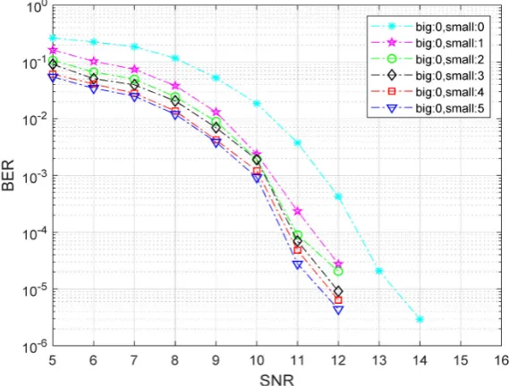
4.1. LMMSE Iterative Detector
In order to work out the performance of the LMMSE iterative detector, we set the number of small iteration respectively. Need to explain that in the simulation the small iteration corresponds to the number of LMMSE iteration and the big iteration corresponds to the number of the process of the detector, decoder and equivalent channel.
In Figure 4, there is no decoder and no overall iteration and only LMMSE iteration, which means the big number is zero and the small number is 0, 1, 2, 3, 4, 5. The number zero means no iteration in LMMSE detector. From Figure 4, there is remarkable improvement in performance. As the number gradually in-creases one by one, the performance rises little by little.
4.2. Big Iteration
To figure out the performance of the big iteration between equivalent channel estimation unit, detection unit and decoder unit, we set the small iterative num-ber to zero. The big iterative numnum-ber is set to 0, 1, 2, 3 respectively. The numnum-ber zero means no information among these three separate units.
From Figure 5, we can learn that the performance improves gradually as the big number increases one by one. The big number 2 improves 0.7 dB approx-imately compared to the big number 0 in bit error rate at 10−4. To reduce the complexity, it is appropriate to set the big number to 2.
Combining big iteration with LMMSE iterative detector, we could achieve much better performance. To achieve the best effect for application, the number of the LMMSE iteration is set to 3, and the number of the big iteration is set to 2, which could make tradeoffs between complexity and performance.
The LMMSE-ISDIC detection algorithm has to do a matrix inversion opera-tion in each iteraopera-tion. The complexity of the algorithm is approximately
( )
3Ο Nt . It also needs to calculate symbolic probability, prior mean and va-riance. However, the complexity maintains at Ο
( )
3t
DOI: 10.4236/jcc.2019.710011 123 Journal of Computer and Communications
[image:8.595.229.519.319.554.2]Figure 4. Bit error rate.
Figure 5. Bit error rate.
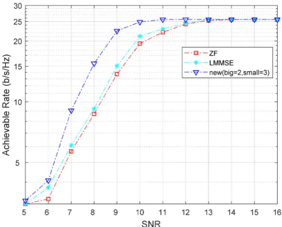
4.3. Comparison
To enhance the performance better, the big iteration and small iteration are combined together and run at once. In the meantime, we also perform ZF de-tector and LMMSE dede-tector.
DOI: 10.4236/jcc.2019.710011 124 Journal of Computer and Communications
Figure 6. Bit error rate.
Figure 7. System achieve rate.
5. Conclusion
[image:9.595.229.517.334.565.2]DOI: 10.4236/jcc.2019.710011 125 Journal of Computer and Communications
Conflicts of Interest
The authors declare no conflicts of interest regarding the publication of this pa-per.
References
[1] Pradhan, B.B. and Roy, L.P. (2014) MIMO Beamforming in Spatially and Tempo-rally Correlated Channel. Proc. IEEE India Conference (INDI-CON), December 2014, 1-5.https://doi.org/10.1109/indicon.2014.7030636
[2] Zheng, L. and Tse, D.N.C. (2003) Diversity and Multiplexing: A Fundamental Tra-deoff in Multiple-Antenna Channels. IEEE Transactions on Information Theory, 49, 1073-1096.https://doi.org/10.1109/tit.2003.810646
[3] Ahmed, I., Khammari, H. and Shahid, A. (2017) Resource Allocation for Transmit Hybrid Beamforming in Decoupled Millimeter Wave Multiuser-MIMO Downlink.
Access IEEE, 5, 170-182.https://doi.org/10.1109/access.2016.2634096
[4] Huang, Z.Y. and Tsai, P.Y. (2011) Efficient Implementation of QR Decomposition for Gigabit MIMO-OFDM Systems. IEEE Transactions on Circuits and Systems I: Regular Papers, 58, 2531-2542.https://doi.org/10.1109/tcsi.2011.2123770
[5] Zhan, C.-Z., Jheng, K.-Y., Chen, Y.-L., Jheng, T.-J. and Wu, A.-Y. (2009) High-Convergence-Speed Low-Computation-Complexity SVD Algorithm for MIMO-OFDM Systems. Proc. International Symposium on VLSI Design Automa-tion and Test, April 2009, 195-198.https://doi.org/10.1109/vdat.2009.5158128
[6] Tsai, P.Y. and Liu, C.Y. (2015) Reduced-Complexity SVD with adjustable Accuracy for Precoding in Large-Scale MIMO Systems. Proc. IEEE Workshop on Signal Processing Systems, October 2015, 1-6.https://doi.org/10.1109/sips.2015.7345023
[7] Rezk, M. and Friedlander, B. (2008) Joint Channel-Symbol Estimation for High-Performance Differential MIMO. Signals Systems and Computers 2008 42nd Asilomar Conference, 1744-1748.https://doi.org/10.1109/acssc.2008.5074725
[8] Wu, C.-L., Skoglund, M., Chen, P.-N. and Han, Y.S. (2009) A Systematic Space-Time Code Design and Its Maximum-Likelihood Decoding for Combined Channel Estimation and Error Correction. IEEE International Symposium, 764-768.
https://doi.org/10.1109/isit.2009.5205641
[9] Wang, D.-M. (2015) 5G Test Platform Algorithm and Principle from NCRL (Na-tional Mobile Communication Research Lab, Southeast University).
[10] Sung, H. (2009) Generalized Channel Inversion Methods for Multiuser MIMO Sys-tems. TCOM, 2009.
[11] Chen, M. and Burr, A.G. (2013) Low-Complexity Channel Selection and Iterative Detection for Overloaded Uplink Multiuser MIMO OFDM System. 2013 IEEE 77th Vehicular Technology Conference, 1-5.
https://doi.org/10.1109/vtcspring.2013.6692621
[12] Gerstacker, W.H., Ralfr, M. and Huber, J.B. (2000) Iterative Equalization with Adaptive Soft Feedback. IEEE Trans. on Commun., 48, 1462-1466.
https://doi.org/10.1109/26.870012
[13] Yang, T.-Q., Wang, J., Wang, D.M. and Zhai, L.J. (2018) Joint Detection in Uplink of Massive MIMO System. IEEE MTT-S International Wireless Symposium, May 2018.https://doi.org/10.1109/ieee-iws.2018.8400958
Telecommunica-DOI: 10.4236/jcc.2019.710011 126 Journal of Computer and Communications
tions, 6-5, September 1995, 507-511.https://doi.org/10.1002/ett.4460060506
[15] Stoica, P., Vikalo, H. and Hassibi, B. (2003) On Joint ML Channel Estimation and Signal Detection for SIMO Channels. Proc. IEEE ICASSP, 4 Apr 2003, 13-16.
https://doi.org/10.1109/icassp.2003.1202529