warwick.ac.uk/lib-publications
Original citation:
Cherkasov, Nikolay, Al-Rawashdeh, Ma ’moun, Ibhadon, Alex O. and Rebrov, Evgeny V.. (2016) Scale up study of capillary microreactors in solvent-free semihydrogenation of 2‐ methyl‐3‐butyn‐2‐ol. Catalysis Today, 273 . pp. 205-212.
Permanent WRAP URL:
http://wrap.warwick.ac.uk/78678
Copyright and reuse:
The Warwick Research Archive Portal (WRAP) makes this work by researchers of the University of Warwick available open access under the following conditions. Copyright © and all moral rights to the version of the paper presented here belong to the individual author(s) and/or other copyright owners. To the extent reasonable and practicable the material made available in WRAP has been checked for eligibility before being made available.
Copies of full items can be used for personal research or study, educational, or not-for-profit purposes without prior permission or charge. Provided that the authors, title and full bibliographic details are credited, a hyperlink and/or URL is given for the original metadata page and the content is not changed in any way.
Publisher’s statement:
© 2016, Elsevier. Licensed under the Creative Commons Attribution-NonCommercial-NoDerivatives 4.0 International http://creativecommons.org/licenses/by-nc-nd/4.0/
A note on versions:
The version presented here may differ from the published version or, version of record, if you wish to cite this item you are advised to consult the publisher’s version. Please see the ‘permanent WRAP url’ above for details on accessing the published version and note that access may require a subscription.
Scale up study of capillary microreactors in solvent-free
semihydrogenation of 2-methyl-3-butyn-2-ol
Nikolay Cherkasova, Ma’moun Al-Rawashdehb, Alex O. Ibhadonc, Evgeny V. Rebrova,d*
a School of Engineering, University of Warwick, Library Road Coventry, CV4 7AL, United
Kingdom
b TreeScaling BV, Helix Building, PO. Box 513, 5600 MB Eindhoven, Netherlands
c Catalysis and Reactor Engineering Research Group, Department of Chemistry and School
of Biological, Biomedical and Environmental Sciences, University of Hull, Cottingham Road,
Hull, HU6 7RX, United Kingdom
d Department of Biotechnology and Chemistry, Tver State Technical University, Tver,
170026, Russia
(*Corresponding Author’s E-mail: [email protected])
ABSTRACT
A 2.5 wt. % Pd/ZnO catalytic coating has been deposited onto the inner wall of capillary
reactors with a diameter of 0.53 and 1.6 mm. The coatings were characterised by XRD, SEM,
TEM and elemental analysis. The performance of catalytic reactors was studied in solvent-free
hydrogenation of 2-methyl-3-butyn-2-ol. No mass transfer limitations was observed in the
reactor with a diameter of 0.53 mm up to a catalyst loading of 1.0 kg(Pd) m-3. The activity and
selectivity of the catalysts has been studied in a batch reactor to develop a kinetic model. The
kinetic model was combined with the reactor model to describe the obtained data in a wide range
of reaction conditions. The model was applied to calculate the range of reaction conditions to
reach a production rate of liquid product of 10-50 kg a day in a single catalytic capillary reactor.
Keywords: Semihydrogenation; catalytic coatings; microreactor; Palladium; alkynol;
Highlights:
- Capillary reactors with a diameter of 0.53 and 1.6 mm were coated with a Pd/ZnO
catalyst
- The alkene selectivity above 97% was obtained in the hydrogenation of
2-methyl-3-butyn-2-ol
- At a coating thickness of 6 µm, the onset of internal diffusion limitations was observed
- A throughput of 28 kg/day per coated channel can be reached according to the reaction
kinetics
Graphical abstract:
1.
Introduction
Process safety and small environmental footprint are one of the main challenges of chemical
industry, and microreactors seem to be one of the most promising technologies. Small
dimensions of microreactors provide large surface to volume ratio, orders of magnitude higher
than that of conventional reactors, and result in high heat and mass transfer rates [1–4]. Quick
mass transfer opens new ways for improved product selectivity by avoiding mass and heat
transfer limitations which eliminate hot spots that generally lead to over-reaction, catalyst
deactivation and rise safety concerns. Another important benefit brought about by microreactors
lies with the ability to use high reaction temperature and pressure without compromising on the
process safety. Even in the case of catastrophic reactor malfunction only very small amount of
harmful substances will be released due to the low liquid hold up [5]. Because of intrinsic safety
and excellent reaction control, microreactors can be utilised under reaction conditions that are
prohibited for large-scale reactors. This opens new operational regimes which results in
processes is the synthesis on demand in smaller scale at the place where products are needed, the
approach which decreases concentration of industrial units and reduces transportation costs [7].
Microreactor technology is successfully used for a number of processes both in academia
and in industry [9–12]. The advantages of microreactors have been clearly demonstrated for
non-catalytic gas-liquid and liquid-liquid reactions that require precise control over reaction
conditions, or involve dangerous chemicals such as corrosive fluorine or explosive
diazo-compounds [13–16]. However, considering that the vast majority of modern chemical processes
utilise heterogeneous catalysts to replace stoichiometric reactions due to obvious economic and
environmental advantages, the application of catalytic coatings in microreactors is
disproportionately scarcely studied [17]. A few gas-phase heterogeneously catalysed reactions
have been studied in various reactions such as Fisher-Tropsch synthesis, CO2 hydrogenation,
water gas shift [18], preferential CO oxidation [19], and complete oxidation of organic
compounds [20] demonstrating a 2-5 fold increase in reaction rates compared to conventional
reactors [21–24].
However, the class of heterogeneously-catalysed multiphase (liquid-liquid or gas-liquid)
reactions received limited attention because of the difficulty to precisely control
catalyst-substrate interactions. The reactions can be performed either using a (i) catalyst particles in a
micro fixed bed configuration [2,25], (ii) magnetically-supported catalysts held at the reactor
walls with magnetic field [26–29], (iii) introducing a slurry of solid catalyst particles into the
reactant flow [30], (iv) catalytic wall coatings obtained via hydrothermal synthesis [31,32] or
methods derived from dipcoating, spincoating or washcoating [33–39]. Micro fixed bed reactors
with a typical pellet size below 100 m seem to offer a simple way of catalyst introduction and
they are suitable for any catalyst. However, catalytic beds have a number of problems such as
bed densification with time resulting in considerable pressure build-up which requires catalyst
dilution with a hard inert material. Also, the removal of heat from the reaction zone to the
external walls could create considerable radial gradients in the reactor in a highly exothermic
reaction. Finally, liquid channelling may result in very wide residence time distribution and
therefore poor product selectivity in consecutive reactions [40–42]. However, for a limited class
of reactions that have no side products, packed-bed reactors can successfully be applied [5,40].
Magnetically-recoverable catalysts offer a convenient way of catalyst introduction and
separation, but their benefits are counterbalanced by more complex reactor design required [43–
45]. A slurry of solid catalyst particles can be introduced into a liquid stream and provides good
selectivity towards intermediate products which is comparable to that of an ideal stirred-tank
reactor [30]. However, this approach requires an additional expensive step to separate catalysts
reactor types in order to provide good catalyst distribution and high conversion. The wall coated
capillary reactors combine simplicity of operation and high throughput with excellent reaction
control which lead to high selectivity towards intermediate products [33,34,46]. Their synthesis
methods have been considerably improved over the last decade and very stable catalytic coatings
were obtained for a range of industrial applications following a recently developed synthesis
method [33].
There exists a limited number of publications describing the upscaling of catalytic capillary
microreactors [47,48]. While the numbering up approach looks very promising to increase the
throughput, it might require 102-105 parallel channels to produce 1-100 ton of product per year.
The exact number of microchannels depends on the maximum allowed pressure drop over the
reactor and the channel length which is often limited by available microfabrication methods [49–
52]. Therefore the numbering up approach needs to be combined with scaling up of the reactor
dimensions to bring the throughput to the industrial scale while avoiding mass or heat transfer
limitations.
The aim of the work was to assess feasibility of industrially-relevant semihydrogenation in
wall-coated capillary microreactors and to study the feasibility of reactor upscaling to reach the
desired production capacity. In this study, selective hydrogenation (semihydrogenation) of
2-methyl-3-butyn-2-ol (MBY) over a Pd/ZnO catalyst was chosen as a model reaction representing
a wide class of important gas-liquid reactions catalysed by a supported heterogeneous catalyst.
The replacement of traditional batch reactors with slurry catalysts by catalytic capillary
microreactors is expected to provide (i) substantial safety benefits due to minimisation of
explosive hydrogen utilisation and (ii) decreased labour costs due to quick process optimisation.
2.
Experimental
2.1.
Reactor preparation and characterisation
Two groups of capillary reactors were used: (i) fused silica capillary microreactors with an
internal diameter of 0.53 mm and a length of 1 m, and (ii) glass tubes millireactors with an
internal diameter of 1.6 mm, and a length of 0.2 m. The reactors are further referred to as
r0.53-xx, where 0.53 is the internal diameter in mm and xx is the total Pd loading in kg m-3(reactor). A
2.5 wt.% Pd/ZnO catalytic coating was deposited onto the inner reactor walls following the
previously reported method [33]. The sol containing catalyst precursors was introduced into the
capillary reactors and the solvent was evaporated by moving the capillary into the oven at 200 oC
at the displacement speed of 0.3 mm s-1. The coating thickness was varied from 2 to 65 µm
surfactants were removed by heating the coated reactor in a vacuum oven (1 mbar residual
pressure) at 200 oC overnight. After cooling to room temperature, the reactors were
consecutively flushed with water and acetone (1 mL min-1, 10 min each) followed by drying in
air.
Several coated reactors were cut and glued on a microscope stubs with epoxy. Then several
(typically 6-9) cross-sections from every reactor were studied on a TM-1000 Hitachi scanning
electron microscope (SEM) in a high-pressure mode to minimise charging without deposition of
an additional conductive coating. The transmission electron microscopy (TEM) images of the
coatings were obtained using a Jeol 2010 transmission electron microscope equipped with an
energy-dispersive X-ray spectrometer (EDX, Oxford Instruments). The study was performed
from 5-8 different regions to obtain representative data. In this study, the coating from the
reactors was removed, dispersed in ethanol under sonication and a few droplets of the dispersion
were dropped on a carbon-coated copper grid.
Powder X-ray diffraction (XRD) measurements were performed using an Empyrean X-ray
diffractometer equipped with monochromatic Kα-Cu X-ray source and a PIXcel linear detector.
The scanning was performed in a stepwise mode within a 2θ range of 20-85o with a step length
of 0.0390o 2θ, and a step time of 60 min studying the coating removed from the capillaries on a
zero background sample holder.
After the reaction, the total catalyst loading in the capillaries was determined dissolving the
coating by withdrawing 1 mL of aqua regia (1:3 volume mixture of concentrated HCl and HNO3,
Sigma-Aldrich) at 0.4 mL min-1 through the capillaries. The resulting solution was collected in a
5 mL volumetric flask and diluted with deionised water. The solutions were studied using a
Perkin Elmer Optima 5300DV emission inductively coupled plasma spectrometer.
Turn-over frequency has been calculated as a ratio of the initial reaction rate (in mol
gcatalyst-1 s-1) and the number of surface Pd sites (in mol gcatalyst-1). The latter was calculated via
dispersion using the empirical correlation D=0.9/dPd(nm) with the average Pd nanoparticle
diameter determined by TEM [53].
2.2.
Capillary reactor testing
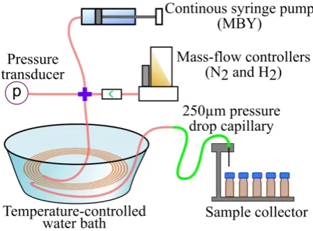
The experimental setup consists of a continuous flow syringe pump fed with MBY
(Sigma-Aldrich, > 98 wt. %) without solvent, mass flow controllers and a pressure transducer connected
via an X-joint to the capillary reactor (Figure 1). The reactor was placed into a thermostatic
water bath at the temperature of 70.0 ±0.4 oC. The reactor outlet was connected to an automatic
0.20±0.03 bar. The liquid samples were diluted 100:1 with hexane and analysed using a Varian
430 gas chromatograph equipped with a 30 m Stabiwax capillary column and a flame ionisation
[image:7.595.218.444.124.291.2]detector.
Figure 1. Scheme of the capillary reactor setup.
2.3.
Reference catalyst synthesis
A reference Pd/ZnO powder catalyst was used for kinetic study in a batch reactor. The
reference catalyst was synthesised by a conventional polyol method [54]. A powder of ZnO, 2 g,
particle sizes < 20 μm (Alfa Aesar), was added into a solution of palladium acetate (>99 wt. %,
Sigma-Aldrich) in 50 mL ethylene glycol (>99 wt. %, Sigma-Aldrich). The amount of palladium
precursor was adjusted to obtain a 2 wt. % Pd/ZnO catalyst because this Pd content provided Pd
nanoparticles of the same dimensions as the 2.5 wt. % Pd/ZnO obtained in capillary reactor
coatings. The dissolved air was displaced with a nitrogen flow of 100 mL min-1 followed by
reflux heating for 2 h. Then, the solution was centrifuged, washed with water (2x30 mL), acetone
(2x30 mL) and dried in nitrogen. The catalyst was characterised by N2 adsorption and TEM. The
complete reduction of Pd was confirmed by elemental analysis data.
2.4.
Batch reactor testing
Hydrogenation in a batch reactor at atmospheric pressure was performed in a 10 mL
two-neck round bottom flask equipped with a water-cooled condenser, and a septum for gas
introduction and liquid withdrawal. The 2 wt. % Pd/ZnO reference catalyst (30.0 mg) was added
to 4.0 mL of MBY without any additional solvent. The reaction mixture was stirred using a
magnetic stirrer. The stirring rates were in the range of 600 – 1200 rpm. The reaction
temperature was controlled with a water bath at 70.0±0.1 oC. The gases were introduced to the
bottom of the reactor via a 250 μm id silica capillary and the flow rates were controlled by
mass-flow controllers. The reactor was flushed with a mass-flow of 20 mL min-1 of nitrogen (99.999 vol.%,
for 1 min to displace nitrogen. Afterwards, the reaction was performed feeding a hydrogen flow
of 15 mL min-1 through the reaction mixture and withdrawing 20 uL of the reaction mixture
regularly for off-line analysis. The absence of mass transfer limitations was confirmed by
studying the reaction rate at various stirring speeds and catalyst amounts. The liquid samples
were diluted 100:1 with heptane and analysed using a Shimadzu 2010 gas chromatograph
equipped with a Stabiwax capillary column and a flame ionisation detector.
3.
Results and Discussion
3.1.
Characterisation of the capillary reactors
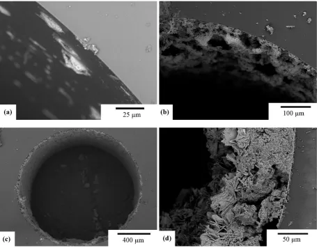
Figure 2 shows representative SEM images of catalytic coatings in the r0.53 reactors. No
continuous ZnO layer was obtained at the catalyst loading corresponding to the Pd content below
0.7 kg(Pd) mr-3. These coatings consisted of separate particles of Pd/ZnO deposited onto the
reactor walls (Figure 2 a,b). Statistical analysis of the coating in 5 capillary reactors with the Pd
loading below 0.7 kg(Pd) mr-3 shows that the dimensions of catalytic particles are independent of
total Pd content and are about 2.3±2.0 µm (average value ± standard deviation). Likely, the
formation of individual particles was caused by capillary forces of the evaporating solvent. At a
higher catalyst content, however, the capillary was coated with a rather uniform catalytic layer
with a thickness of 11.9±6.0 µm. The coating consisted of ZnO crystallite platelets which formed
Figure 2. Cross sectional SEM photographs of the 0.53 mm i.d. capillary reactors wall-coated with Pd/ZnO, total Pd content is (a) 0.24, (b) 0.64, (c, d) 2.35 kg (Pd) m-3(reactor).
SEM study of various r1.6 reactors showed that the coating was not uniform at the catalyst
loading below 0.7 kg(Pd) mr-3. The coating consisted of individual ZnO particles with a mean
size of 6.7±5.2 µm. At a higher catalyst content, a uniform coating was obtained onto the reactor
walls with the thickness increasing from 36±22 to 65±30 µm for the r1.6-1.0 and r1.6-1.8
reactors, respectively. A Pd loading in all the capillary reactors of 2.53±0.37 wt. % was
determined by EDX analysis. This value is in a good agreement with the nominal Pd loading of
Figure 3. Cross sectional SEM photographs of the 1.6 mm i.d. capillary reactors wall-coated with Pd/ZnO, total Pd content is (a) 0.17, (b) 1.03, (c) 1.23, (d) 1.76 kg (Pd) m-3(reactor).
The powder XRD pattern of the Pd/ZnO catalyst (Figure 4) showed that wurtzite was the
only ZnO phase in the coatings. Its crystallite size was estimated using Scherrer’s formula to be
about 30 nm. This is a typical size obtained in the developed sol-gel method after a calcination
step at 200 oC as low calcination temperature prevents sintering of ZnO nanoparticles. A small
[image:10.595.86.545.55.411.2]Pd peak is present at 40o 2θ.
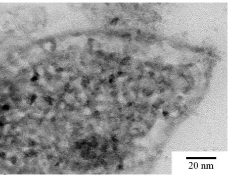
Figure 5 shows a characteristic TEM image of a coating detached from the r1.6-1.0 reactor.
It can been seen in Figure 5 that the Pd particles with a mean size of 3.0±1.0 nm are evenly
distributed through the ZnO framework. These particles are formed by several smaller
nanoparticles about 1.3 nm in diameter. The morphology and dimensions of Pd nanoparticles
were the same for r0.53 and r1.6 capillary reactors, i.e. change in the total Pd content in the
reactors was caused only by the increase in the Pd/ZnO coating thickness.
Figure 5. A representative TEM microphotograph of the Pd/ZnO coating removed from the r1.6-1.0 reactor.
3.2.
Semihydrogenation in capillary reactors
Two series of capillary reactors, r0.53 and r1.6, were studied in solvent-free MBY
hydrogenation. The conditions were selected to ensure that the conversion of MBY was below
80 %, which allowed for determination of apparent reaction rates directly from MBY conversion
as the reaction rate follows a pseudo-zero order kinetics [55,56]. The alkene selectivity above
97.5 % was observed for all the reactors studied except for the r1.6-1.8 reactor. These data show
that there were no internal diffusion limitations of MBY or liquid channelling that usually
substantially decrease selectivity.
It can be seen in Figure 6, the MBY conversion in r0.53 reactors with different Pd loadings
was linearly proportional to the catalyst loading up to a Pd content of 0.75 kg m-3 at a liquid flow
rate of 10 µL min-1. This confirms the absence of mass transfer limitations. At a higher Pd
loading of 2.4 kg m-3, the full MBY conversion was observed therefore the flow rates was
increased to 40 µL min-1 to get kinetic data. At the higher flow rate, the MBY conversion
increased linearly with catalyst loading up to a Pd content of 0.7 kg m-3. At a higher Pd loading
of 2.4 kg m-3 the reaction rate was affected by the onset of mass-transfer limitations. For the r1.6
reactors, similarly, the MBY conversion was proportional to the Pd loading in the whole range of
[image:11.595.219.445.182.356.2]Figure 6. MBY hydrogenation over a Pd/ZnO catalytic coating in capillary reactors (■,♦) 0.53 mm i.d. (r0.53) and (▲) 1.6 mm i.d. (r1.6). Liquid flow rate: (■,▲) 10 µL min-1 or (♦) 40 µL min-1, reaction
temperature: 70 C, H2 flow rate: 10 mL min-1 (STP), absolute reaction pressure 1.2 bar.
The reactant conversion in a zero-order catalytic reaction is proportional to the amount of
catalyst in the reactor, the fraction of the total reactor volume occupied by the liquid (which is
determined by the liquid hold up) and inversely proportional to the liquid reactant flow rate. The
zero-order reaction kinetics is described by Eq. 1:
) 1
( '
0 0
res MBY
MBY C k
C (1),
where τres is the liquid residence time ( L
V cat res
F V
), Vcat is the catalyst volume, Lis the
liquid hold-up in the reactor, and Fv is the volumetric liquid flow rate, and ' 0
k is the pseudo
zero-order reaction rate constant. Eq. 1 can be rearranged in terms of MBY conversion (XMBY):
res MBY k
X '
0
(2)
Figure 7 shows the change in reactant concentration as a function of residence time. It can
be seen that no mass transfer limitations were observed for the r0.53 up to the catalytic loading
of 1 kg(Pd) mr-3. For the r1.6 reactors, the observed rates were lower than that in the r0.53
reactors suggesting the presence of mass transfer limitations.
Figure 7. MBY hydrogenation as a function of normalised catalyst mass over a Pd/ZnO catalytic coating
or (♦) 40 µL min-1, reaction temperature: 70 C, H
2 flow rate: 10 mL min-1 (STP), absolute reaction pressure
1.2 bar.
3.3.
Semihydrogenation in a batch reactor
The MBY semihydrogenation was performed over a 2 wt. % Pd/ZnO catalyst in a batch
reactor. The reaction rate was independent on the stirring speed above 900 rpm confirming the
absence of mass transfer limitations. The catalyst was non-porous (Vpore<50 μL g-1) with a
specific surface area of 4.1 m2 g-1. The Pd nanoparticles were 3.2 ±1.1 nm according to TEM
data (not shown). The Pd dispersion in the model catalyst was the same as that in the catalytic
coatings which allowed direct data comparison between the model catalyst and catalytic
coatings.
The reaction kinetics was modelled to explain the difference in the performance between
r0.53 and r 1.6 reactors. The MBY hydrogenation reaction scheme (Figure 8) consists of three
main reactions: (i) MBY hydrogenation to MBE followed by (ii) MBE hydrogenation to MBA
[image:13.595.86.246.597.724.2]and (iii) a direct hydrogenation step of MBY to MBA.
Figure 8. Scheme of 2-methyl-3-butyn-2-ol hydrogenation reactions.
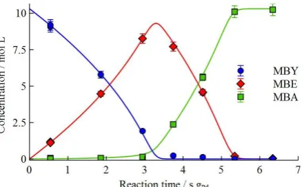
The concentration profiles of the reactant and products in the MBY hydrogenation over the
2 wt. % Pd/ZnO catalyst in the batch reactor are shown in Figure 9. The concentration profiles
were modelled using the Langmuir-Hinshelwood kinetics with competitive adsorption of organic
species and dissociated hydrogen on the catalyst surface with the rate equation 3-5 [55,56].
Considering vapour pressure of MBY of 0.27 bar at the reaction temperature, hydrogen pressure
(PH2) in the system was taken as 0.73 bar.
2 2 1 2 * 1 1 ) ( MBE MBY MBA
H MBY C Q C C Q p C k r (3) 2 2 1 2 * 2 2 ) ( MBE MBY MBA
H MBE C Q C C Q p C k r (4) 2 2 1 2 2 * 3 3 ) ( MBE MBY MBA
where CMBY, CMBE and CMBA are the concentrations of the organic species, k*1-k*3 are the apparent
rate constants of the corresponding reaction steps, Q1=KMBE/KMBY, Q2=KMBA/KMBY are the ratios
of adsorption constants.
The rate equations (Eqs. 3-5) were solved numerically in the Matlab software using a
Runge-Kutta method optimised for stiff systems of ordinary differential equations (ode23tb
solver). The regression analysis was performed using a non-linear weighted least squares routine
using Levenberg-Marquardt with the statistical weights reciprocal to the experimental
uncertainties. The error analysis of the kinetic parameters was performed using a Monte-Carlo
method analysing results on 2000 data sets with the initial data normally distributed around the
experimental results [57].
Figure 9. Concentration profiles of solvent-free MBY hydrogenation in a batch reactor on the 2. %
Pd/ZnO reference catalyst at 70C and ambient H2 pressure. Curves present results of kinetic modelling.
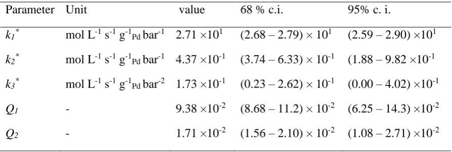
The obtained constants are listed in Table 1. The values of k2* and k3* are more than 100
times lower than k1* value which explains the very high MBE selectivity observed in Figure 9.
The k3* rate constant has wide confidence intervals and demonstrates that the experimental data
can be accurately described considering only two consecutive reaction stages. This result is in
line with the data reported for Pd and Pd-Bi catalysts [55,56,58]. The KMBE/KMBY and
KMBA/KMBY ratios are below 0.1. This result agrees with previously published data reporting
preferential adsorption of alkynes on Pd catalysts which is another factor contributing to the high
alkene selectivity [59,60]. TOF calculated using TEM data was 93 s-1, which is in good
agreement with the TOF of about 60 s-1 obtained for 0.2% Pd/ZnO catalyst under similar
[image:14.595.220.441.274.410.2]Table 1. Kinetic parameters for MBY hydrogenation obtained by regression analysis of experimental data
Parameter Unit value 68 % c.i. 95% c. i.
k1* mol L-1 s-1 g-1Pd bar-1 2.71 ×101 (2.68 – 2.79) × 101 (2.59 – 2.90) ×101
k2* mol L-1 s-1 g-1Pd bar-1 4.37 ×10⁻¹ (3.74 – 6.33) × 10-1 (1.88 – 9.82 ×10⁻¹
k3* mol L-1 s-1 g-1Pd bar-2 1.73 ×10⁻¹ (0.23 – 2.62) × 10-1 (0.00 – 4.02) ×10-1
Q1 - 9.38 ×10⁻² (8.68 – 11.2) × 10-2 (6.25 – 14.3) ×10-2
Q2 - 1.71 ×10⁻² (1.56 – 2.10) × 10-2 (1.08 – 2.71) ×10-2
c.i. =confidence interval
3.4.
Semihydrogenation in a capillary reactor
The kinetic parameters were applied to the capillary reactors and the corresponding parity
plot is shown in Figure 10. There is a good agreement between the experimental data and model
predictions for the r0.53 reactors, which confirms the absence of mass transfer limitations. The
deviations in the area of low MBY conversions are likely caused by uncertainties in elemental
analysis and variations in the dispersion of Pd nanoparticles. The experimental data obtained in
the r0.53-2.4 reactor demonstrated substantial deviation from predicted values due to the
presence of substantial mass transfer limitations in this reactor.
Figure 10. Parity plot for MBY conversion in the microreactors for capillary 0.53 mm i.d. microreactors (r0.53) at liquid flow rates of (■) 10 µL min-1 and (♦) 40 µL min-1, and in 1.6 mm i.d. millireactors (r1.6) at
liquid flow rate of (▲) 10 µL min-1. Dashed line corresponds to perfect agreement. The numbers in the
parentheses refer to the Pd loading in kg m-3 in the corresponding reactors.
For the r1.6 reactors, the picture was completely different as all the points show reaction
rates much lower than that expected for the modelled conditions, i.e. without mass transfer
limitations. The Weisz-Prater criterion was calculated to estimate internal mass transfer
limitations of hydrogen and organic species (Eq. 6):
eff s
c P
W
D C
h N
2
where is the apparent reaction rate, hc is the coating thickness, Cs is the concentration of the
diffusing species with the effective diffusivity of Deff. Diffusivities of dissolved hydrogen and
organic species of 7.0· 10-9 m2 s-1 and 2.0· 10-9 m2 s-1 were estimated according to Vannice [63].
A value of NW-P = 0.5 for hydrogen in the coating with a thickness of 6 µm, indicates the
presence of internal diffusion limitations. For organic species, however, diffusion limitations
were highly unlikely because their concentrations, 4 orders of magnitude higher than that of
hydrogen, resulted in NW-P numbers below 10-3. Still, at the high MBY conversion and for thick
catalytic coating observed in the r1.6-1.8 reactor, NW-P reached values ~1 suggesting pore
limitations of MBE. Indeed, low MBE selectivity of 91 % for the r1.6-1.8 reactor indicates that
pore diffusion limitations were observed for both organic and hydrogen species. The observed
linearity with Pd content in Figure 7 is likely caused by comparable intrinsic reaction and mass
transfer rates under the studied conditions. Furthermore, pore diffusion limitations cannot be
removed at a higher hydrogen pressure because the increase in the concentration of dissolved
hydrogen will be compensated by the increased reaction rates resulting in the same Weisz-Prater
numbers.
The pore limitations agree with the modelling performed by Warnier, who showed that pore
diffusion limitations are observed faster than external transfer in a gas-liquid slug flow [64].
Considering the boundary value for the Weisz-Prater number of 0.3, the thickness of the catalytic
layer where no hydrogen diffusion limitations are expected is 5 µm. This thickness is in excellent
agreement with the experimental results, which show that mass transfer was observed for all the
reactors with the thicker catalytic coating (Figure 6).
Considering good agreement of the kinetic model with experiment and the absence of mass
transfer limitations for the reactors coated with 5 µm catalyst, the model was used to estimate
maximum hydrogenation throughput for a range of capillary reactors of various lengths and
diameters. Pressure drop in the reactors was estimated using Lockhart-Martinelli correlation
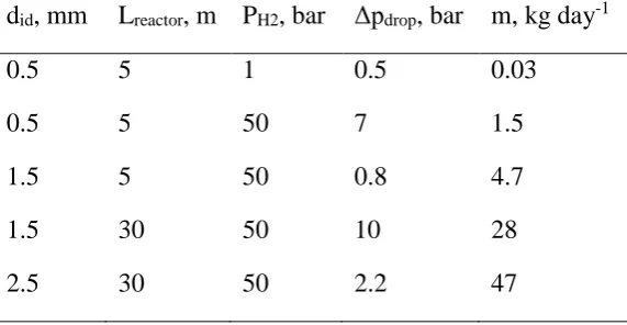
[65,66] neglecting consumption of hydrogen in the reaction. The results presented in Table 2
show that at a reaction pressure of 50 bar, the throughput of about 1.5 kg day-1 can be reached in
a 5 m reactor with a diameter of 0.5 mm operated at a pressure drop of 7 bar. Such a substantial
pressure drop can be decreased by increasing the reactor diameter, allowing for longer reactors
and higher throughputs reaching up to 28 kg day-1. Further increase in diameter allows for even
higher throughput, but the onset of external mass transfer limitations is expected under such
conditions [64]. The throughput can further be increased via numbering up and increasing the
Table 2. Estimations of the maximum throughput and pressure drop in capillary reactors coated with 5 µm of 2.5% Pd/ZnO if no external mass transfer limitations apply.
did, mm Lreactor, m PH2, bar Δpdrop, bar m, kg day-1
0.5 5 1 0.5 0.03
0.5 5 50 7 1.5
1.5 5 50 0.8 4.7
1.5 30 50 10 28
2.5 30 50 2.2 47
4.
Conclusions
Two series of capillary reactors with the internal diameters of 0.53 and 1.6 mm were wall–coated
with Pd/ZnO and tested in solvent-free hydrogenation of a vitamin A precursor,
2-methyl-3-butyn-2-ol (MBY). Selectivity towards alkene was above 97.5 % in all the reactors studies,
demonstrating feasibility of semihydrogenation in capillary reactors with minimal by-product
formation. Correlation of the observed MBY conversion with the total Pd content in the reactors
indicated that no mass transfer limitations were observed for the microreactors 0.53 mm i.d. up
to about 1 kg(Pd) m(reactor)-3. Kinetic modelling of solvent-free MBY hydrogenation was performed
in a batch reactor and the model was applied to the reactions in capillary reactors, confirming
that mass transfer limitations were observed for the microreactor with the Pd loading of 2.4 kg(Pd)
m-3 and all the millireactors 1.6 mm id. Calculation of the Weisz-Prater number demonstrated
that internal diffusion of hydrogen was the limiting phenomena, so maximum thickness of the
coating that creates negligible hydrogen pore diffusion is 5 µm. The kinetic model was used to
estimate maximum throughput of a range of capillary reactors wall coated with a 5 µm layer of
2.5 wt. % Pd/ZnO catalyst considering that no external mass transfer limitations apply. The
estimations showed that throughput of about 10-50 kg day-1 of liquid product can be achieved in
a single reactor at the reaction pressure of 50 bar, while further increase is expected by
numbering up and process intensification using higher temperature and pressure, microwave or
radiofrequency heating.
Acknowledgments
Authors are grateful to Dr. C. Wiles for the access to her equipment, to the European
European Research Council (ERC) project 279867, the Russian Science Foundation (project
15-13-20015) for financial support.
References
[1] S.G. Newman, K.F. Jensen, The role of flow in green chemistry and engineering, Green
Chem. 15 (2013) 1456–1472. doi:10.1039/c3gc40374b.
[2] K.F. Jensen, Microreaction engineering — is small better?, Chem. Eng. Sci. 56 (2001)
293–303. doi:10.1016/S0009-2509(00)00230-X.
[3] K. Jähnisch, V. Hessel, H. Löwe, M. Baerns, Chemistry in microstructured reactors,
Angew. Chemie Int. Ed. 43 (2004) 406–46. doi:10.1002/anie.200300577.
[4] E. V. Rebrov, Use of microtechnologies for intensifying industrial processes, Theor.
Found. Chem. Eng. 44 (2010) 791–799. doi:10.1134/S004057951005026X.
[5] B.P. Mason, K.E. Price, J.L. Steinbacher, A.R. Bogdan, T.D. McQuade, Greener
approaches to organic synthesis using microreactor technology, Chem. Rev. 107 (2007) 2300–
2318. doi:10.1021/cr050944c.
[6] V. Hessel, D. Kralisch, N. Kockmann, T. Noël, Q. Wang, Novel process windows for
enabling, accelerating, and uplifting flow chemistry, ChemSusChem. 6 (2013) 746–789.
doi:10.1002/cssc.201200766.
[7] V. Hessel, D. Kralisch, N. Kockmann, Novel Process Windows: Innovative Gates to
Intensified and Sustainable Chemical Processes, John Wiley & Sons, 2014.
[8] D. Reay, C. Ramshaw, A. Harvey, Process Intensification: Engineering for Efficiency,
Sustainability and Flexibility, Butterworth-Heinemann, 2013.
http://books.google.com/books?hl=en&lr=&id=QV_U0Kbhh1UC&pgis=1 (accessed December
27, 2014).
[9] P. Watts, S.J. Haswell, The application of microreactors for small scale organic synthesis,
Chem. Eng. Technol. 28 (2005) 290–301. doi:10.1002/ceat.200407124.
[10] C. Wiles, P. Watts, Continuous flow reactors: a perspective, Green Chem. 14 (2012) 38–
54. doi:10.1039/c1gc16022b.
[11] D.M. Roberge, L. Ducry, N. Bieler, P. Cretton, B. Zimmermann, Microreactor
Technology: A Revolution for the Fine Chemical and Pharmaceutical Industries?, Chem. Eng.
Technol. 28 (2005) 318–323. doi:10.1002/ceat.200407128.
approaches to organic synthesis using microreactor technology., Chem. Rev. 107 (2007) 2300–
18. doi:10.1021/cr050944c.
[13] S.G. Newman, L. Gu, C. Lesniak, G. Victor, F. Meschke, L. Abahmane, et al., Rapid
Wolff–Kishner reductions in a silicon carbide microreactor, Green Chem. 16 (2014) 176–180.
doi:10.1039/C3GC41942H.
[14] B.J. Deadman, S.G. Collins, A.R. Maguire, Taming Hazardous Chemistry in Flow: The
Continuous Processing of Diazo and Diazonium Compounds, Chem. - A Eur. J. 21 (2015) 2298–
2308. doi:10.1002/chem.201404348.
[15] R.D. Chambers, M. a. Fox, G. Sandford, Elemental fluorine : Part 18. Selective direct
fluorination of 1,3-ketoesters and 1,3-diketones using gas/liquid microreactor technology, Lab
Chip. 5 (2005) 1132. doi:10.1039/b504675k.
[16] T.H. Rehm, Photochemical Fluorination Reactions - A Promising Research Field for
Continuous-Flow Synthesis Introduction – Why fluorine ?, Chem. Eng. Technol. (2015) article
ASAP 10.1002/ceat.201500195. doi:10.1002/ceat.201500195.
[17] E. V Rebrov, A. Berenguer-Murcia, A.E.H. Wheatley, B.F.G. Johnson, J.C. Schouten,
Thin catalytic coatings on microreactor walls A way to make industrial processes more efficient,
Chim. Oggi-Chemistry Today. 27 (2009) 4–7. <Go to ISI>://000268662700002.
[18] A.R. Dubrovskiy, E. V. Rebrov, S.A. Kuznetsov, J.C. Schouten, A microstructured
reactor/heat-exchanger for the water-gas shift reaction operated in the 533-673 K range, Catal.
Today. 147 (2009) 198–203. doi:10.1016/j.cattod.2009.07.037.
[19] P. V. Snytnikov, M.M. Popova, Y. Men, E. V. Rebrov, G. Kolb, V. Hessel, et al.,
Preferential CO oxidation over a copper-cerium oxide catalyst in a microchannel reactor, Appl.
Catal. A Gen. 350 (2008) 53–62. doi:10.1016/j.apcata.2008.07.036.
[20] I.Z. Ismagilov, E.M. Michurin, O.B. Sukhova, L.T. Tsykoza, E. V Matus, M.A.
Kerzhentsev, et al., Oxidation of organic compounds in a microstructured catalytic reactor,
Chem. Eng. J. 135 (2008) S57–S65. doi:10.1016/j.cej.2007.07.036.
[21] I. Miguel-García, M. Navlani-García, J. García-Aguilar, Á. Berenguer-Murcia, D.
Lozano-Castelló, D. Cazorla-Amorós, Capillary microreactors based on hierarchical SiO2
monoliths incorporating noble metal nanoparticles for the Preferential Oxidation of CO, Chem.
Eng. J. 275 (2015) 71–78. doi:10.1016/j.cej.2015.04.020.
[22] B. Tidona, A. Urakawa, P. Rudolf von Rohr, High pressure plant for heterogeneous
catalytic CO2 hydrogenation reactions in a continuous flow microreactor, Chem. Eng. Process.
[23] S. Allahyari, M. Haghighi, A. Ebadi, Direct synthesis of DME over nanostructured CuO–
ZnO–Al2O3/HZSM-5 catalyst washcoated on high pressure microreactor: Effect of catalyst
loading and process condition on reactor performance, Chem. Eng. J. 262 (2015) 1175–1186.
doi:10.1016/j.cej.2014.10.062.
[24] B. Todić, V. V. Ordomsky, N.M. Nikačević, A.Y. Khodakov, D.B. Bukur, Opportunities
for intensification of Fischer–Tropsch synthesis through reduced formation of methane over
cobalt catalysts in microreactors, Catal. Sci. Technol. 5 (2015) 1400–1411.
doi:10.1039/C4CY01547A.
[25] S.K. Ajmera, M.W. Losey, K.F. Jensen, M.A. Schmidt, Microfabricated packed-bed
reactor for phosgene synthesis, AIChE J. 47 (2001) 1639–1647. doi:10.1002/aic.690470716.
[26] R.B.N. Baig, R.S. Varma, Magnetically retrievable catalysts for organic synthesis.,
Chem. Commun. 49 (2013) 752–70. doi:10.1039/c2cc35663e.
[27] T.K. Houlding, E. V. Rebrov, Application of alternative energy forms in catalytic reactor
engineering, Green Process. Synth. 1 (2012) 19–31. doi:10.1515/greenps-2011-0502.
[28] L.M. Rossi, N.J.S. Costa, F.P. Silva, R. Wojcieszak, Magnetic nanomaterials in catalysis:
advanced catalysts for magnetic separation and beyond, Green Chem. 16 (2014) 2906–3380.
doi:10.1039/c4gc00164h.
[29] T. Zhang, X. Zhang, X. Yan, L. Kong, G. Zhang, H. Liu, et al., Synthesis of
Fe3O4@ZIF-8 magnetic core-shell microspheres and their potential application in a capillary
microreactor, Chem. Eng. J. 228 (2013) 398–404. doi:10.1016/j.cej.2013.05.020.
[30] A.-K. Liedtke, F. Bornette, R. Philippe, C. de Bellefon, Gas–liquid–solid “slurry Taylor”
flow: Experimental evaluation through the catalytic hydrogenation of 3-methyl-1-pentyn-3-ol,
Chem. Eng. J. 227 (2013) 174–181. doi:10.1016/j.cej.2012.07.100.
[31] E. V. Rebrov, G.B.F. Seijger, H.P.A. Calis, M.H.J.M. de Croon, C.M. van den Bleek,
J.C. Schouten, Preparation of highly ordered single layer ZSM-5 coating on prefabricated
stainless steel microchannels, Appl. Catal. A Gen. 206 (2001) 125–143.
doi:10.1016/S0926-860X(00)00594-9.
[32] M.J.M. Mies, J.L.P. Van Den Bosch, E. V. Rebrov, J.C. Jansen, M.H.J.M. de Croon, J.C.
Schouten, Hydrothermal synthesis and characterization of ZSM-5 coatings on a molybdenum
support and scale-up for application in micro reactors, Catal. Today. 110 (2005) 38–46.
doi:10.1016/j.cattod.2005.09.015.
[33] N. Cherkasov, A.O. Ibhadon, E. V. Rebrov, Novel synthesis of thick wall coatings of
acetylene alcohols in capillary microreactors, Lab Chip. 15 (2015) 1952–1960.
doi:10.1039/C4LC01066C.
[34] E. V Rebrov, A. Berenguer-Murcia, H.E. Skelton, B.F.G. Johnson, A.E.H. Wheatley, J.C.
Schouten, Capillary microreactors wall-coated with mesoporous titania thin film catalyst
supports, Lab Chip. 9 (2009) 503–6. doi:10.1039/b815716b.
[35] M. Faustini, B. Louis, P.A. Albouy, M. Kuemmel, D. Grosso, Preparation of Sol− Gel
Films by Dip-Coating in Extreme Conditions, J. Phys. Chem. C. 114 (2010) 7637–7645.
http://pubs.acs.org/doi/abs/10.1021/jp9114755 (accessed April 5, 2014).
[36] E. V Rebrov, E.A. Klinger, A. Berenguer-Murcia, E.M. Sulman, J.C. Schouten, Selective
hydrogenation of 2-methyl-3-butyne-2-ol in a wall-coated capillary microreactor with a
Pd25Zn75/TiO2 catalyst, Org. Process Res. Dev. 13 (2009) 991–998.
http://pubs.acs.org/doi/abs/10.1021/op900085b (accessed May 20, 2013).
[37] L.N. Protasova, E. V. Rebrov, H.E. Skelton, A.E.H. Wheatley, J.C. Schouten, A kinetic
study of the liquid-phase hydrogenation of citral on Au/TiO2 and Pt–Sn/TiO2 thin films in
capillary microreactors, Appl. Catal. A Gen. 399 (2011) 12–21.
doi:10.1016/j.apcata.2011.03.021.
[38] C.H. Hornung, B. Hallmark, M.R. Mackley, I.R. Baxendale, S.V. Ley, A Palladium Wall
Coated Microcapillary Reactor for Use in Continuous Flow Transfer Hydrogenation, Adv.
Synth. Catal. 352 (2010) 1736–1745. doi:10.1002/adsc.201000139.
[39] O. Muraza, E. V. Rebrov, J. Chen, M. Putkonen, L. Niinistö, M.H.J.M. de Croon, et al.,
Microwave-assisted hydrothermal synthesis of zeolite Beta coatings on ALD-modified
borosilicate glass for application in microstructured reactors, Chem. Eng. J. 135 (2007) 117–120.
doi:10.1016/j.cej.2007.07.003.
[40] M. Irfan, T.N. Glasnov, C.O. Kappe, Heterogeneous catalytic hydrogenation reactions in
continuous-flow reactors., ChemSusChem. 4 (2011) 300–16. doi:10.1002/cssc.201000354.
[41] C.G. Frost, L. Mutton, Heterogeneous catalytic synthesis using microreactor technology,
Green Chem. 12 (2010) 1687. doi:10.1039/c0gc00133c.
[42] B.H. Alsolami, R.J. Berger, M. Makkee, J.A. Moulijn, Catalyst Performance Testing in
Multiphase Systems: Implications of Using Small Catalyst Particles in Hydrodesulfurization,
Ind. Eng. Chem. Res. 52 (2013) 9069–9085. doi:10.1021/ie4010749.
[43] R. Easterday, C. Leonard, O. Sanchez-Felix, Y. Losovyj, M. Pink, B.D. Stein, et al.,
Fabrication of magnetically recoverable catalysts based on mixtures of Pd and iron oxide
21652–60. doi:10.1021/am5067223.
[44] A. Zoabi, S. Omar, R. Abu-Reziq, Chiral Ruthenium Catalyst Immobilized within
Magnetically Retrievable Mesoporous Silica Microcapsules for Aqueous Asymmetric Transfer
Hydrogenations, Eur. J. Inorg. Chem. 2015 (2015) 2101–2109. doi:10.1002/ejic.201403212.
[45] C.P. Park, D.-P. Kim, A Microchemical System with Continuous Recovery and
Recirculation of Catalyst-Immobilized Magnetic Particles, Angew. Chemie. 122 (2010) 6977–
6981. doi:10.1002/ange.201002490.
[46] M. Ueno, T. Suzuki, T. Naito, H. Oyamada, S. Kobayashi, Development of microchannel
reactors using polysilane-supported palladium catalytic systems in capillaries., Chem. Commun.
(2008) 1647–9. doi:10.1039/b715259k.
[47] J. Fernández, S. Chatterjee, V. Degirmenci, E. V. Rebrov, Scale-up of an RF heated
micro trickle bed reactor to a kg/day production scale, Green Process. Synth. (2015).
doi:10.1515/gps-2015-0035.
[48] N.G. Patil, F. Benaskar, E. V. Rebrov, J. Meuldijk, L.A. Hulshof, V. Hessel, et al.,
Continuous Multitubular Millireactor with a Cu Thin Film for Microwave-Assisted
Fine-Chemical Synthesis, Ind. Eng. Chem. Res. 51 (2012) 14344–14354. doi:10.1021/ie300754z.
[49] M. Al-Rawashdeh, F. Yue, N.G. Patil, T.A. Nijhuis, V. Hessel, J.C. Schouten, et al.,
Designing flow and temperature uniformities in parallel microchannels reactor, AIChE J. 60
(2014) 1941–1952. doi:10.1002/aic.14443.
[50] M. Al-Rawashdeh, F. Yu, T.A. Nijhuis, E. V. Rebrov, V. Hessel, J.C. Schouten,
Numbered-up gas–liquid micro/milli channels reactor with modular flow distributor, Chem. Eng.
J. 207-208 (2012) 645–655. doi:10.1016/j.cej.2012.07.028.
[51] M. Al-Rawashdeh, L.J.M. Fluitsma, T.A. Nijhuis, E. V. Rebrov, V. Hessel, J.C.
Schouten, Design criteria for a barrier-based gas-liquid flow distributor for parallel
microchannels, Chem. Eng. J. 181-182 (2012) 549–556. doi:10.1016/j.cej.2011.11.086.
[52] M. Al-Rawashdeh, J. Zalucky, C. Müller, T.A. Nijhuis, V. Hessel, J.C. Schouten,
Phenylacetylene hydrogenation over [Rh(NBD)(PPh3) 2]BF4 catalyst in a numbered-up
microchannels reactor, Ind. Eng. Chem. Res. 52 (2013) 11516–11526. doi:10.1021/ie4009277.
[53] M. Boudart, D.E. Mears, M.A. Vannice, Kinetics of heterogeneous catalytic reactions,
Ind. Chim. Belge. 32 (1967) 281–284.
[54] R.R.E. Cable, R.E.R. Schaak, R. V September, V. Re, M. Recei, V. October,
Low-temperature solution synthesis of nanocrystalline binary intermetallic compounds using the
http://pubs.acs.org/doi/abs/10.1021/cm0520113 (accessed July 9, 2014).
[55] Z. Wu, N. Cherkasov, G. Cravotto, E. Borretto, A.O. Ibhadon, J. Medlock, et al.,
Ultrasound- and Microwave-Assisted Preparation of Lead-Free Palladium Catalysts: Effects on
the Kinetics of Diphenylacetylene Semi-Hydrogenation, ChemCatChem. 7 (2015) 952–959.
doi:10.1002/cctc.201402999.
[56] N. Cherkasov, A.O. Ibhadon, A. McCue, J.A. Anderson, S.K. Johnston, Palladium–
bismuth intermetallic and surface-poisoned catalysts for the semi-hydrogenation of
2-methyl-3-butyn-2-ol, Appl. Catal. A Gen. 497 (2015) 22–30. doi:10.1016/j.apcata.2015.02.038.
[57] J.S. Alper, R.I. Gelb, Standard errors and confidence intervals in nonlinear regression:
comparison of Monte Carlo and parametric statistics, J. Phys. Chem. 94 (1990) 4747–4751.
doi:10.1021/j100374a068.
[58] N. Cherkasov, A.O. Ibhadon, E. V. Rebrov, Solvent-free Semihydrogenation of
Acetylene Alcohols in a Capillary Reactor coated with a Pd-Bi/TiO2 Catalyst, Appl. Catal. A
Gen. 515 (2016) 108–115. doi:10.1016/j.apcata.2016.01.019.
[59] D. Mei, P. Sheth, M. Neurock, C. Smith, First-principles-based kinetic Monte Carlo
simulation of the selective hydrogenation of acetylene over Pd(111), J. Catal. 242 (2006) 1–15.
doi:10.1016/j.jcat.2006.05.009.
[60] M. García-Mota, J. Gómez-Díaz, G. Novell-Leruth, C. Vargas-Fuentes, L. Bellarosa, B.
Bridier, et al., A density functional theory study of the “mythic” Lindlar hydrogenation catalyst,
Theor. Chem. Acc. 128 (2010) 663–673. doi:10.1007/s00214-010-0800-0.
[61] M. Crespo-Quesada, M. Grasemann, N. Semagina, A. Renken, L. Kiwi-Minsker,
Kinetics of the solvent-free hydrogenation of 2-methyl-3-butyn-2-ol over a structured Pd-based
catalyst, Catal. Today. 147 (2009) 247–254. doi:10.1016/j.cattod.2008.09.035.
[62] N. Semagina, A. Renken, D. Laub, L. Kiwi-Minsker, Synthesis of monodispersed
palladium nanoparticles to study structure sensitivity of solvent-free selective hydrogenation of
2-methyl-3-butyn-2-ol, J. Catal. 246 (2007) 308–314. doi:10.1016/j.jcat.2006.12.011.
[63] M.A. Vannice, Kinetics of Catalytic Reactions, Springer Science+Business Media, New
York, 2005. doi:10.1007/b136380.
[64] M.J.F. Warnier, Taylor flow hydrodynamics in gas-liquid-solid micro reactors, 2009.
[65] D. Chisholm, A theoretical basis for the Lockhart-Martinelli correlation for two-phase
flow, Int. J. Heat Mass Transf. 10 (1967) 1767–1778. doi:10.1016/0017-9310(67)90047-6.
[66] R.W. Lockhart, R.C. Martinelli, Proposed correlation of data for isothermal two-phase,