VMware vCloud
Implementation
Example
Public vCloud Service Provider
Table of Contents
1. Purpose and Overview . . . . 4
1.1 Executive Summary . . . .4
1.2 Business Requirements . . . .4
1.3 Use Cases . . . .4
1.4 Document Purpose and Assumptions . . . .4
2. VMware vCloud Architecture Design Overview . . . . 5
2.1 vCloud Definition . . . .5
2.2 vCloud Component Design Overview . . . .6
3. vSphere Architecture Design Overview . . . . 6
3.1 High Level Architecture . . . .6
3.2 Site Considerations . . . .8
3.3 Design Specifications . . . .8
4. vSphere Architecture Design – Management Cluster . . . . 9
4.1 Compute Logical Design . . . .9
4.1.1 Datacenters . . . .9
4.1.2. vSphere Clusters . . . .9
4.1.3. Host Logical Design . . . .9
4.2 Network Logical Design . . . .11
4.3 Shared Storage Logical Design . . . .11
4.4 Management Components . . . .11
4.5 Management Component Resiliency Considerations . . . . 12
5. vSphere Architecture Design – Resource Groups . . . . 13
5.1 Compute Logical Design . . . .13
5.1.1. Datacenters . . . .13
5.1.2. vSphere Clusters . . . .13
5.1.3. Host Logical Design . . . .14
5.2 Network Logical Design . . . .14
5.3 Shared Storage Logical Design . . . .15
5.4 Resource Group Datastore Considerations . . . .16
5.4.1. Datastore Sizing Estimation . . . . 17
6. vCloud Provider Design . . . .17
6.1 Abstractions and VMware vCloud Director Constructs . . . . 17
6.2 Provider vDCs . . . . 18
6.4 Networks . . . . 20
6.4.1. External Networks . . . . 20
6.4.2. Network Pools . . . . 20
6.4.3. Networking Use Cases . . . .21
6.5 Catalogs . . . .23
7. vCloud Security . . . . 24
7.1 vSphere Security . . . .24
7.1.1. Host Security . . . .24
7.1.2. Network Security . . . .24
7.1.3. vCenter Security . . . .24
7.2 VMware vCloud Director Security . . . .24
8. vCloud Management . . . . 24
8.1 vSphere Host Setup Standardization . . . .24
8.2 VMware vCloud Director Logging . . . .24
8.3 vSphere Host Logging . . . .25
8.4 VMware vCloud Director Monitoring . . . .25
1. Purpose and Overview
1.1 Executive Summary
ACME Service Provider will be implementing a “service provider” cloud built on VMware technologies. The objective of this project is to create a consumer-oriented self-service model to allow ACME Service Provider’s customers to individually consume its aggregated resources.
This document defines the vCloud architecture and provides detailed descriptions and specifications of the architectural components and relationships. This design is based on a combination of VMware best practices and specific business requirements and goals.
1.2 Business Requirements
The vCloud for ACME Service Provider will have the following characteristics and provide: • Compute capacity to support 1,500 virtual machines, which are predefined workloads.
• Secure multi-tenancy, permitting more than one organization to share compute resources. In a public cloud, organizations typically represent different customers, and each customer may have several environments such as development or production.
• A self-service portal where Infrastructure as a Service (IaaS) can be consumed from a catalog of predefined applications (vApp Templates).
• A chargeback mechanism, so that resources can be methodically allocated, their consumption metered, and the associated cost provided back to the appropriate consumer.
Refer to the corresponding Service Definition for further details.
1.3 Use Cases
The target use cases for the vCloud include the following workloads: • Development and test
• Pre-production • Demos • Training
• Tier 2 and Tier 3 applications
1.4 Document Purpose and Assumptions
This vCloud Architecture Design document is intended to serve as a reference for architects, and assumes they have familiarity with VMware products, including VMware vSphere, vCenter, and VMware vCloud Director. The vCloud architecture detailed in this document is organized into these sections:
SEC TION DESCRIPTION
vCloud Definition Inventory of components that comprise the cloud solution
vSphere – Management vSphere and vCenter components that support running workloads
vSphere – Resources Resources for cloud consumption
Design organized by compute, networking, and shared storage
Detailed through logical and physical design specifications and considerations
Management and Security Considerations as they apply to vSphere and VMware vCloud Director Management components
vCloud Logical Design VMware vCloud Director objects and configuration Relationship of VMware vCloud Director to vSphere objects
This document is not intended as a substitute for detailed product documentation. Refer to the installation and administration guides for the appropriate product as necessary for further information.
2. VMware vCloud Architecture Design Overview
2.1 vCloud Definition
The VMware vCloud is comprised of the following components:
VCLOU D COM PON ENT DESCRIPTION
VMware vCloud Director Abstracts and coordinates underlying resources Includes:
• VMware vCloud Director Server (1 or more instances, each installed on a Linux VM and referred to as a “cell”) • VMware vCloud Director Database (1 instance per
clustered set of VMware vCloud Director cells) • vSphere compute, network and storage resources
VMware vSphere Foundation of underlying cloud resources
Includes:
• VMware ESXi hosts (3 or more instances for Management cluster and Resource Group)
• vCenter Server (1 instance managing a management cluster of hosts, and 1 instance managing a resource group of hosts reserved for vCloud consumption) • vCenter Server Database (1 instance per vCenter Server)
VCLOU D COM PON ENT DESCRIPTION
VMware vShield Provides network security services including NAT and firewall
Includes:
• vShield Edge (deployed automatically as virtual appliances on hosts by VMware vCloud Director) • vShield Manager (1 instance per vCenter Server in
the cloud resource groups)
VMware vCenter Chargeback Provides resource metering, and chargeback models Includes:
• vCenter Chargeback Server (1 instance) • Chargeback Data Collector (1 instance) • vCloud Data Collector (1 instance) • VSM Data Collector (1 instance)
2.2 vCloud Component Design Overview
The components comprising the vCloud are detailed in this document in the following sections:
DESIG N SEC TION VCLOU D COM PON ENT(S)
vSphere Architecture – Management Cluster • vCenter Server and vCenter Database • vCenter Cluster and ESXi hosts
• vCenter Chargeback Server and Database • vCenter Chargeback Collectors
• vShield Manager and vShield Edge(s)
• VMware vCloud Director Cell(s) and Database (Oracle) vSphere Architecture – Resource Group • vCenter Server(s) and vCenter Database(s)
• vCenter Cluster(s) and ESXi hosts
3. vSphere Architecture Design Overview
3.1 High Level Architecture
vSphere resources are organized and separated into:
• A management cluster containing all core components and services needed to run the cloud.
• One or more resource groups that represent dedicated resources for cloud consumption. Each resource group is a cluster of ESXi hosts managed by a vCenter Server, and is under the control of VMware vCloud Director. Multiple resource groups can be managed by the same VMware vCloud Director.
Reasons for organizing and separating vSphere resources along these lines are:
• Facilitating quicker troubleshooting and problem resolution. Management components are strictly contained in a relatively small and manageable management cluster. Otherwise, running on a large set of host clusters could lead to situations where it is time-consuming to track down and manage such workloads.
• Management components are separate from the resources they are managing.
• Resources allocated for cloud use have little overhead reserved. For example, cloud resource groups would not host vCenter VMs.
• Resource groups can be consistently and transparently managed, carved up, and scaled horizontally. The high level logical architecture is depicted as follows.
Shared Storage
SAN
Virtual Machines Shared Storage
SAN
Shared Storage
SAN
Compute Resources
vSphere4.1
Compute Resources
vSphere4.1
Provider vDC
Basic Provider vDCCommitted
Compute Resources
vSphere4.1
Resource Groups Management Cluster
VM
VM VM VM VM VM VCD vSM vCenter
VM
VM VM VM VM VM AD/DNS Oracle 11g Chargeback
VM
VM VM VM VM VM NFS MSSQL Log/Mon
Figure 1 – vCloud Logical Architecture Overview
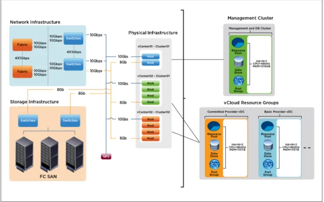
The following diagram depicts the physical design corresponding to the logical architecture previously described.
Figure 2 – vCloud Physical Design Overview
3.2 Site Considerations
The management cluster resides in a single physical Datacenter.
Resource groups all reside within a single physical Datacenter. This ensures a consistent level of service, as it avoids potential latency issues if workloads need to be moved Datacenter to another over a slower or less reliable network.
Neither secondary nor DR sites are in the scope of this project.
3.3 Design Specifications
The architecture is described by a logical design that is independent of hardware-specific details. The focus is on components, their relationships, and quantity.
4. vSphere Architecture Design – Management
Cluster
4.1 Compute Logical Design
The compute design encompasses the ESXi host clusters. In this section the scope is further limited to only the infrastructure supporting the management component workloads.
4.1.1. Datacenters
The management cluster is contained within a single vCenter datacenter.
4.1.2. vSphere Clusters
The management cluster will be comprised of the following vSphere clusters.
AT TRIBUTE SPECIFICATION
Number of ESXi Hosts 4
VMware DRS Configuration Fully automated
VMware DRS Migration Threshold 3 stars
VMware HA Enable Host Monitoring Yes
VMware HA Admission Control Policy Cluster tolerances 1 host failure (Percentage based)
VMware HA Percentage 25%
VMware HA Admission Control Response Prevent VMs from being powered on if they violate availability constraints
VMware HA Default VM Restart Priority N/A
VMware HA Host Isolation Response Leave VM Powered On
VMware HA Enable VM Monitoring Yes
VMware HA VM Monitoring Sensitivity Medium Table 1 – vSphere Clusters – Management Cluster
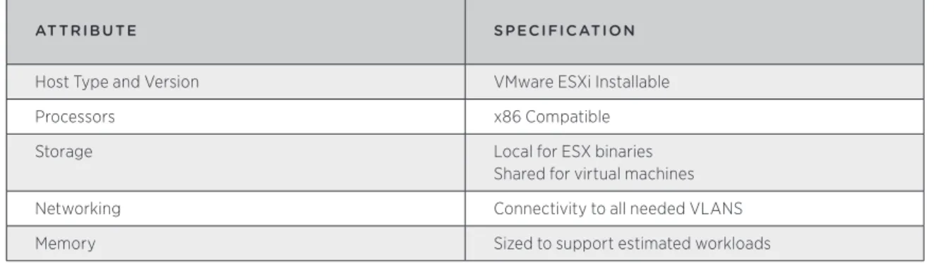
4.1.3. Host Logical Design
Each ESXi host in the management cluster will have the following specifications.
AT TRIBUTE SPECIFICATION
Host Type and Version VMware ESXi Installable
Processors x86 Compatible
Storage Local for ESX binaries
Shared for virtual machines
Networking Connectivity to all needed VLANS
Memory Sized to support estimated workloads
4.2 Network Logical Design
The network design section defines how the vSphere virtual networking will be configured. Following best practices, the network architecture will meet these requirements:
• Separate networks for vSphere management, VM connectivity, vMotion traffic, and Fault Tolerance logging (VM record/replay) traffic
• Redundant vSwitches with at least 2 active physical adapter ports each
• Redundancy across different physical adapters to protect against NIC or PCI slot failure • Redundancy at the physical switch level
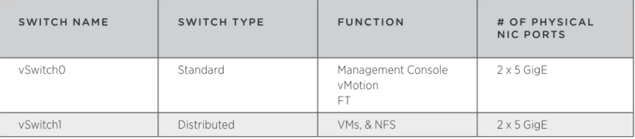
SWITCH NAM E SWITCH T YPE FU NC TION # OF PHYSICAL
NIC PORTS
vSwitch0 Standard Management Console
vMotion FT
2 x 5 GigE
vSwitch1 Distributed VMs, & NFS 2 x 5 GigE
Table 3 – Virtual Switch Configuration – Management Cluster
When using the distributed virtual switch, dvUplink ports are the number of physical NIC ports on each host. The physical NIC ports will be connected to redundant physical switches.
The following diagrams depict the virtual network infrastructure designs: Management Cluster
Management VLAN U
vmnic0
vmnic1 VLAN V
vMotion vSwitch0
VLAN W VLAN X vSwitch1
VLAN Y
vmnic4 dvSwitch1(optional)
vmnic5 DMZ
Mgmt
FT
vmnic2
vmnic3
Distribution
Switch1 Switch1Core
Distribution Switch2
Core Switch2
PARAM E TER SE T TING
Load Balancing Route based on NIC load (for vDS)
Failover Detection Link status
Notify Switches Enabled
Failover Order All active except for Management Network
Management Console: Active, Standby vMotion: Standby, Active
Table 4 – Virtual Switch Configuration Settings – Management Cluster
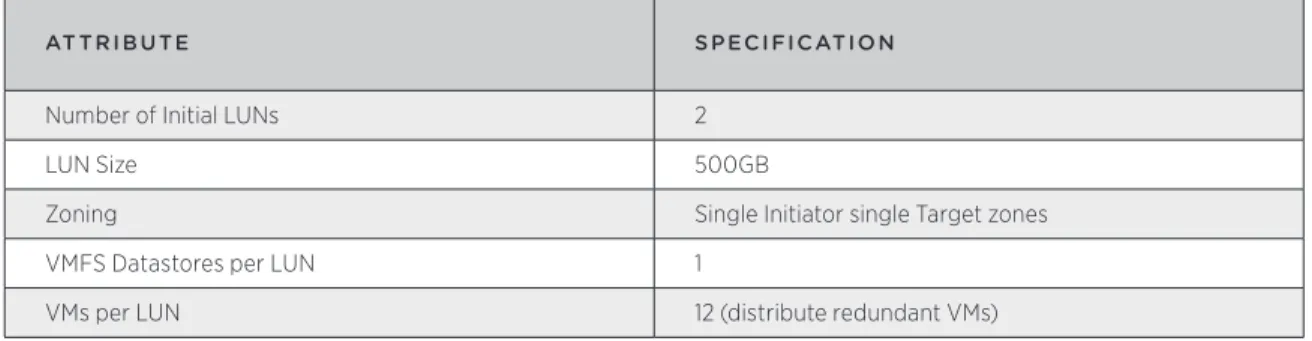
4.3 Shared Storage Logical Design
The shared storage design section defines how the vSphere datastores will be configured. The same storage will be used for both the Management cluster as well as the VMware vCloud Director Resource groups. Following best practices, the shared storage architecture will meet these requirements:
• Storage paths will be redundant at the host (connector), switch, and storage array levels. • All hosts in a cluster will have access to the same datastores.
AT TRIBUTE SPECIFICATION
Number of Initial LUNs 2
LUN Size 500GB
Zoning Single Initiator single Target zones
VMFS Datastores per LUN 1
VMs per LUN 12 (distribute redundant VMs)
Table 5 – Shared Storage Logical Design Specifications – Management Cluster
4.4 Management Components
The following components will run as VMs on the management cluster hosts: • vCenter Servers
• vCenter Database
• vCenter Update Manager Database • vCloud Director Cells
• vCloud Director Database • vCenter Chargeback Server • vCenter Chargeback Database • vShield Manager
VMware vCloud Director Cells are stateless in operation with all information stored in the database. There is some caching that happens at the VMware vCloud Director cell level, such as SSL session data, but all refreshes and updates are done to information stored in the database. As such, the database is critical to the operation of VMware vCloud Director. In a production environment, VMware recommends the database be housed in either a cluster configuration, or at the very least have a hot standby available.
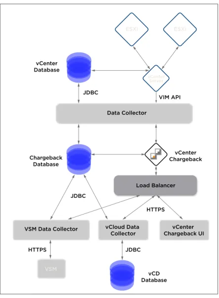
VSM Data Collector
Load Balancer Data Collector
vCloud Data
Collector Chargeback UIvCenter
VSM
ESXi ESXi
vCenter Server
vCenter Database
vCD Database Chargeback
Database
vCenter Chargeback JDBC
JDBC
VIM API
JDBC HTTPS
HTTPS
Figure 4 – vCenter Chargeback Logical Diagram
4.5 Management Component Resiliency Considerations
The following management components will rely on HA and FT for redundancy. MANAG EM ENT
COM PON ENT HA ENAB LED? F T ENAB LED?
vCenter Server Yes No
VMware vCloud Director Yes No
vCenter Chargeback Server Yes No
vShield Manager Yes Yes
5. vSphere Architecture Design – Resource
Groups
5.1 Compute Logical Design
The compute design encompasses the ESXi host clusters. In this section the scope is further limited to only the infrastructure dedicated to the cloud workloads.
5.1.1. Datacenters
Resource groups can map to different datacenters and are managed by a single vCenter server.
5.1.2. vSphere Clusters
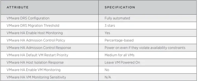
All vSphere clusters will be configured similarly with the following specifications.
AT TRIBUTE SPECIFICATION
VMware DRS Configuration Fully automated
VMware DRS Migration Threshold 3 stars
VMware HA Enable Host Monitoring Yes
VMware HA Admission Control Policy Percentage-based
VMware HA Admission Control Response Power on even if they violate availability constraints VMware HA Default VM Restart Priority Medium for all VMs
VMware HA Host Isolation Response Leave VM Powered On
VMware HA Enable VM Monitoring No
VMware HA VM Monitoring Sensitivity N/A Table 7 – vSphere Cluster Configuration – Resource Groups
The resource groups will have the following vSphere clusters.
CLUSTER NAM E VCENTER SERVER
NAM E # OF HOSTS HA PERCENTAG E
RG01COMM01 stg-vcvshield.acme.com 4 50%
RG01PAYG01 stg-vcvshield.acme.com 4 50%
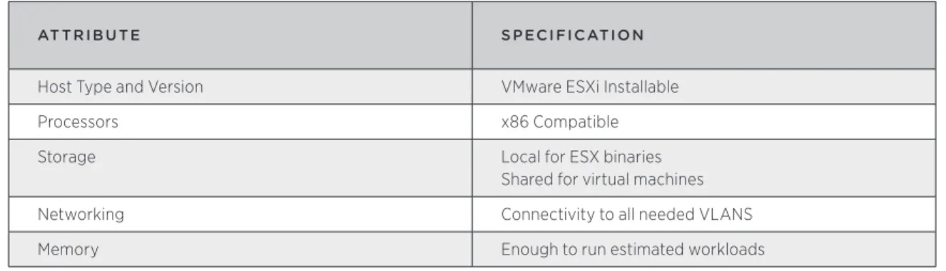
5.1.3. Host Logical Design
Each ESXi host in the resource groups will have the following specifications.
AT TRIBUTE SPECIFICATION
Host Type and Version VMware ESXi Installable
Processors x86 Compatible
Storage Local for ESX binaries
Shared for virtual machines
Networking Connectivity to all needed VLANS
Memory Enough to run estimated workloads
Table 9 – Host Logical Design Specifications – Resource Groups
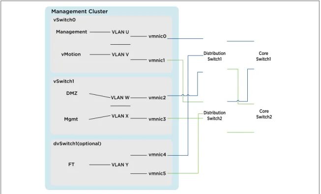
5.2 Network Logical Design
The network design section defines how the vSphere virtual networking will be configured. Following best practices, the network architecture will meet these requirements:
• Separate networks for vSphere management, VM connectivity, vMotion traffic, traffic • Redundant vSwitches with at least 2 active physical adapter ports
• Redundancy across different physical adapters to protect against NIC or PCI slot failure • Redundancy at the physical switch level
SWITCH
NAM E SWITCH T YPE FU NC TION # OF PHYSICAL
NIC PORTS
vSwitch0 Standard Management Console
vMotion
2 x 3.4 GigE
dvSwitch1 Distributed External Networks 2 x3.3 GigE
dvSwitch2 Distributed Network Pools 2 x 3.3 GigE
Table 10 – Virtual Switch Configuration – Resource Groups
When using the distributed virtual switch, dvUplink ports are the number of physical NIC ports on each host. The physical NIC ports will be connected to redundant physical switches.
Management Cluster
Management VLAN U
vmnic0
vmnic1 VLAN V
vMotion vSwitch0
VLAN W VLAN X vSwitch1
VLAN Y
vmnic4 dvSwitch1(optional)
vmnic5 DMZ
Mgmt
FT
vmnic2
vmnic3
Distribution
Switch1 Switch1Core
Distribution Switch2
Core Switch2
Figure 5 – vSphere Logical Network Design – Resource Groups
PARAM E TER SE T TING
Load Balancing Route based on NIC load (for vDS)
Failover Detection Link status
Notify Switches Enabled
Failover Order All active except for Management Network
Management Console: Active, Standby vMotion: Standby, Active
Table 11 – Virtual Switch Configuration Settings – Resource Groups
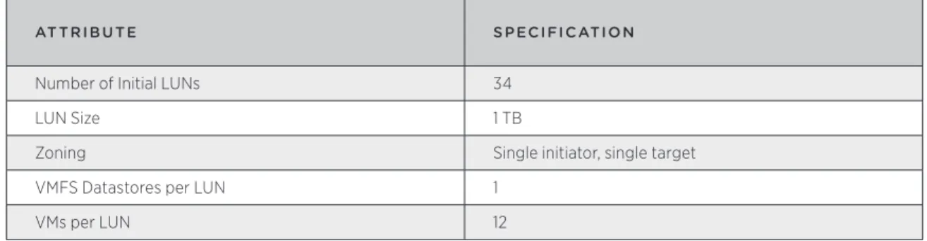
5.3 Shared Storage Logical Design
The shared storage design section defines how the vSphere datastores will be configured. Following best practices, the shared storage architecture will meet these requirements: • Storage paths will be redundant at the host (connector), switch, and storage array levels. • All hosts in a cluster will have access to the same datastores.
AT TRIBUTE SPECIFICATION
Number of Initial LUNs 34
LUN Size 1 TB
Zoning Single initiator, single target
VMFS Datastores per LUN 1
VMs per LUN 12
Table 12 – Shared Storage Logical Design Specifications – Resource Groups
5.4 Resource Group Datastore Considerations
The most common aspect of LUN/datastore sizing is what limit should be implemented regarding the number of VMs per datastore. The reason for limiting this number is to minimize the potential for SCSI locking and to spread the I/O across as many storage processors as possible. Most mainstream storage vendors will provide VMware-specific guidelines for this limit, and VMware recommends an upper limit of 25 VMs per VMFS datastore, regardless of storage platform. In many cases it is forgotten that the number of VMs per LUN is also influenced by the size and I/O requirements of the VM but perhaps more importantly the selected storage solution and even disk types.
When VMware vCloud Director provisions VMs it automatically places the VMs on datastores based on the free disk space of each of the associated datastores in an organization virtual data center (Org vDC). Due to this mechanism, we will need to keep the size of the LUNs and the number of VMs per LUN relatively low to avoid possible I/O contention.
When considering the number of VMs to place on a single datastore, some of the following factors should be considered in conjunction with any recommended VMs-per-LUN ratio:
• Average VM workload/profile (in particular, the amount of I/O)
• Typical VM size (including configuration files, logs, swap files, and snapshot files) • VMFS metadata
• Max requirement for IOPs and throughput per LUN, dependency on storage array and design • Max RTO, if a LUN is lost, i.e. your backup and restore design
If we approach this from an average I/O profile it would be tempting to create all LUNs the same, say as RAID 5, and let the law of averages take care of I/O distribution across all the LUNs and VMs on those LUNs. Another approach would be to create LUNs with different RAID profiles based on anticipated workloads within an Organization. This would dictate creating Provider virtual datacenters (vDCs) that took into account the allocation models as well as the storage profile in use. We would end up with the following types of Provider vDCs as an example:
• Commited_High_Performance • Commited_Generic
• PAYG_High_Performance • PAYG_Generic
As a starting point, VMware recommends starting with RAID 5 storage RAID profiles and only creating storage tiers as one-offs to address specific customer requirements. Obviously this creates opportunity in a service provider environment for tiered pricing as well.
5.4.1. Datastore Sizing Estimation
An estimate of the typical datastore size can be approximated by considering the following factors.
VARIAB LE VALU E
Maximum Number of VMs per Datastore 15
Average Size of Virtual Disk(s) per VM 60 GB
Average Memory Size per VM 2 GB
Safety Margin 10%
Table 13 – Datastore Size Estimation Factors
For example, ((15 * 60GB) + (15 * 2GB))+ 10% = (900GB + 30GB) * 1.1 = 1.023TB
6. vCloud Provider Design
6.1 Abstractions and VMware vCloud Director Constructs
A key tenet of the cloud architecture is resource pooling and abstraction. VMware vCloud Director further abstracts the virtualized resources presented by vSphere by providing logical constructs that map to vSphere logical resources:
• Organization – organizational unit to which resources (vDCs) are allocated.
• Virtual Datacenter (vDC) – Deployment environments, scoped to an organization, in which virtual machines run. • Provider Virtual Datacenter – vSphere resource groupings that power vDCs, further segmented out into
organization vDCs.
• Organization Virtual Datacenter (vDC) – Subset of provider vDC.
vCD
vSphere
Physical
Org Network
External Network Network Pool Provider vDC
Organization vDC
Resource Pool Compute Cluster
Physical Host Storage Array
Physical Network VLAN
(d)VS Port Group vDS Datastore
6.2 Provider vDCs
The following diagram shows how the Provider vDCs map back to vSphere resources.
provider01
(1TB) provider02(1TB)
VMFS VMFS
Basic Provider vDC
vhost03 vhost04 vhost05 vhost06
provider03
(1TB) provider04(1TB)
VMFS VMFS
Committed Provider vDC
vhost07 vhost08 vhost09 vhost10
vCenter01.vmware.com
Figure 7 – Provider vDCs in Resource Groups
All ESXi hosts will belong to a vSphere cluster which will be associated with one and only one Provider vDC. A vSphere cluster will scale to 25 hosts, allowing for up to 14 clusters per vCenter Server (the limit is bound by the maximum number of hosts per datacenter possible) and an upper limit of 10,000 VMs (this is a vCenter limit) per resource group.
The recommendation is to start with 8 hosts in a cluster and add resources (Hosts) to the cluster as dictated by customer consumption. However, per the public cloud service definition, each of the Provider vDCs (Basic and Committed) will start with 4 hosts. When utilization of the resources reaches 60%, it is recommended that a new Provider vDC/cluster be deployed for all new customers. This provides for growth within the Provider vDCs for the existing customers without necessitating a migration of customers as their utilization nears maxing out a cluster’s resources.
As an example, a fully loaded resource group will contain 14 Provider vDCs, and up to 350 ESXi hosts, giving an average VM consolidation ratio of 26:1 assuming a 5:1 ratio of vCPU:pCPU. To increase this ratio, ACME Service Provider would need to increase the vCPU:pCPU ratio that they are willing to support. The risk associated with an increase in CPU over commitment is mainly in degraded overall performance that can result in higher than acceptable vCPU ready times. The vCPU:pCPU ratio is based on the amount of CPU over commitment, for the available cores, that ACME Service Provider feels comfortable with. For VMs that are not busy this ratio can be increased without any undesirable effect on VM performance. Monitoring of vCPU ready times helps identify if the ratio needs to be increased or decreased on a per cluster basis. A 5:1 ratio is a good starting point for a multicore system.
A Provider vDC can map to only one vSphere cluster, but can map to multiple datastores and networks. Multiple Provider vDCs are used to map to different types/tiers of resources.
• Compute – this is a function of the mapped vSphere clusters and the resources that back it • Storage – this is a function of the underlying storage types of the mapped datastores
• Networking – this is a function of the mapped vSphere networking in terms of speed and connectivity Multiple Provider vDCs are created for the following reasons:
• The cloud requires more compute capacity than a single vSphere cluster (a vSphere resource pool cannot span vSphere clusters)
• Tiered storage is required; each Provider vDC maps to datastores on storage with different characteristics • Requirement for workloads to run on physically separate infrastructure
AT TRIBUTE SPECIFICATION
Number of Provider vDCs 2
Number of Default External Networks 1 per Organization Table 14 – Provider vDC Specifications
PROVIDER
VDC CLUSTER DATASTOR ES VSPH ER E N E T WOR KS FU NC TION
RG01COMM01 vcd01vc01C01 vcd01vc01c01l001 vcd01vc01c01l002 vcd01vc01c01l003
Internet01 PvDC for 400 VMs
RG01PAYG01 vcd01vc01C02 vcd01vc01c02l004 vcd01vc01c02l005 vcd01vc01c02l006
Internet01 PvDC for 400 VMs
Table 15 – Provider vDC to vSphere Mapping
VMware recommends assessing workloads to assist in sizing. Following is a standard sizing table that can be used as a reference for future design activities.
VM SIZE DISTRIBUTION
1 vCPU / 1 GB RAM 45%
2 vCPU / 2 GB RAM 35%
4 vCPU / 4 GB RAM 15%
8 vCPU / 8 GB RAM 5%
Total 100%
Table 16 – Virtual Machine Sizing and Distribution
6.3 Organizations
ORGANIZATION NAM E DESCRIPTION
Total World Cable Cable company with Test Dev Environment
Emca Corporation Corporate Internet Presence
Totally High School E-Learning Infrastructure
Table 17 – Organizations
6.4 Networks
AT TRIBUTE SPECIFICATION
Number of Default External Networks 1 per Organization Number of Default vApp Networks End-user controlled
Number of default Organization Networks 2 (Internet, Organization Isolated)
Network Pool Types Used vCloud Director Network Isolation (vCD-NI) Is a Pool of Public Routable IP Addresses Available? Yes, for Internet access – assigned as a /27 Table 18 – Network Specifications
6.4.1. External Networks
ACME Service Provider will provide the following sets of External Networks based on need: • Internet Port group-backed Network
• VPN/MPLS Port group-backed network (optional)
Part of the provisioning for an organization will involve creating an External network for each Organization, and a VPN network if desired, and associating them with the required Org Networks. The public cloud service definition requires that the Internet connection be a Nat/Routed Org network with at least a /27 networks associated with it.
6.4.2. Network Pools
For the vCD-NI-Backed pool it is recommended that the transport VLAN be a VLAN that is not in use within the ACME Service Provider infrastructure for increased security and isolation.
6.4.3. Networking Use Cases
ACME Service Provider will provide the following four use cases (one optional VPN use case) for their customers based on the use cases that are currently being deployed in their physical environment:
1. Customers should be able to completely isolate vApps for their Development and/or Test Users
vApp01
Isolated vApp
DB
1.12 Web1.11 App1.10
vApp01Net
Figure 8 – vApp Isolated Network
2. Customers should be able to connect to the Organization Networks either directly or via fencing and the Organization Networks will not have access to any public Internet.
vApp01
vApp Bridged to Org
DB
1.12 Web1.11 App1.10
vApp02
DB
1.15 Web1.14 App1.13
DevTest_Net(OrgNet)
vApp01Net vApp02Net
This is an example for a Dev Test environment where developers will use the different IPs in their vApps.
vApp1a
vApp fenced from Org
DB
1.12 Web1.11 App1.10
vApp1b
DB
1.12 Web1.11 App1.10
vApp01Net vApp02Net
DevTest_Net(OrgNet)
Figure 10 – vApp Network Fenced to Org Network
This is an example for Dev Test where developers will have duplicate IPs in their vApps.
3. Customers should be able to connect the Organization Networks either directly or via fencing to the External Networks.
vApp1a
Org Bridged to External
DB
1.12 Web1.11 App1.10
vApp1b
DB
1.12 Web1.11 App1.10
vApp01Net vApp02Net
DevTest_Net(OrgNet) VPN_Net(ExternalNet)
This would be a good option when the External network is a private Network such as a VPN or MPLS terminated network.
vApp1a
Org Firewalled from External
DB
1.12 Web1.11 App1.10
vApp01Net
DevTest_Net(OrgNet) vApp1b
DB
1.12 Web1.11 App1.10
vApp02Net
vApp01Net vApp02Net
DevTest_Net(OrgNet)
Internet_Net(ExternalNet)
Figure 12 – vApp Network Fenced to Fenced Org Network
This is one way to connect the External network and preserve VLANs by sharing the same VLAN for the Internet_Net among multiple Organizations The vShield Edge is needed to provide NAT and firewall services for the different Organizations.
Once the External Networks have been created, a VMware vCloud Director Administrator can create the Organization Networks as shown above. The vShield Edge (VSE) device is needed to perform Address
translation between the different networks. The VSE can be configured to provide for port address translation to jump hosts located inside the networks or to gain direct access to individual hosts.
VMware recommends separating External and Organization networks by using two separate dvSwitches. The External networks will be provisioned on dvSwitch1 also known as a ProviderDVS. This is where all the static port groups will also be defined such as VPN and MPLS connections as the VLANs for these networks will be known ahead of time.
The Organization networks on the other hand will be provisioned off of dvSwitch2. This is where all the
Organization networks will be created as well as the different types of vCD-NI-backed and VLAN-backed pools. The connectivity for this dvSwitch will also be changed to allow for the higher MTU of 1524 needed to
accommodate vCD-NI networks.
6.5 Catalogs
The catalog will contain ACME Service Provider-specific templates that are to be made available to all organizations. ACME Service Provider will make available a set of catalog entries to cover the classes of virtual machines, templates, and media as specified in the corresponding Service Definition.
7. vCloud Security
7.1 vSphere Security
7.1.1. Host Security
Chosen in part for its limited management console functionality, ESXi will be configured with a strong root password stored following corporate password procedures. ESXi lockdown mode will also be enabled to prevent root access to the hosts over the network, and appropriate security policies and procedures will be created and enforced to govern the systems. Because ESXi cannot be accessed over the network, sophisticated host-based firewall configurations are not required.
7.1.2. Network Security
Virtual switch security settings will be as follows.
FU NC TION SE T TING
Promiscuous Mode Management cluster – Reject
Resource Group - Reject
MAC Address Changes Management cluster – Reject
Resource Group - Reject
Forged Transmits Management cluster – Reject
Resource Group - Reject Table 19 – Virtual Switch Security Settings
7.1.3. vCenter Security
vCenter Server is installed using a local administrator account. When vCenter Server is joined to a domain, this will result in any domain administrator gaining administrative privileges to vCenter. To remove this potential security risk, a new vCenter Administrators group will be created in Active Directory and assigned the vCenter Server Administrator Role, making it possible to remove the local Administrators group from this role.
7.2 VMware vCloud Director Security
Standard Linux hardening guidelines need to be applied to the VMware vCloud Director VM. There is no need for local users, and the root password will only be needed during install and upgrades to the VMware vCloud Director binaries. Additionally, certain network ports must be open for vCloud Director use. Refer to the vCloud Director Administrator’s guide for further information.
8. vCloud Management
8.1 vSphere Host Setup Standardization
Host Profiles can be used to automatically configure network, storage, security and other features. This feature along with automated installation of ESXi hosts is used to standardize all host configurations.
ACME Service Provider will need to standardize on a build process with their hardware integrator to make sure by the time the equipment is delivered to an ACME Service Provider datacenter very little needs to be changed to get a host up and running, short of rolling the rack in and cabling it into the environment.
VM Monitoring is enabled on a cluster level within HA and uses the VMware Tools heartbeat to verify a virtual machine is alive. When a virtual machine fails, causing VMware Tools heartbeat to not be updated, VM
As such VMware recommends enabling both VMware HA and VM Monitoring on the Management cluster and the Resource Group clusters.
8.2 VMware vCloud Director Logging
Each VMware vCloud Director cell logs audit messages to the database where they are retained for 90 days by default. If log retention is needed longer than 90 days and or centralized logging is required, an external Syslog server can be configured and used as a duplicate destination for the events that are logged.
8.3 vSphere Host Logging
Remote logging to a central host provides a way to greatly increase administration capabilities. Gathering log files on a central server facilitates monitoring of all hosts with a single tool as well as enables aggregate analysis and the ability to search for evidence of coordinated attacks on multiple hosts. This will apply to the following log analysis:
5.1.4. messages (host log) 5.1.5. hostd (host agent log) 5.1.6. vpxa (vCenter agent log)
Within each ESXi host, Syslog behavior is controlled by the Syslog advanced settings. These settings determine the central logging host that will receive the Syslog messages. The hostname must be resolvable using DNS. For this design, each ESXi host will be configured to send log files to a central Syslog server residing in the management cluster.
8.4 VMware vCloud Director Monitoring
The following items should be monitored through VMware vCloud Director. As of VMware vCloud Director 1.0 this will need to be done with custom queries to VMware vCloud Director using the Admin API to get the consumption data on the different components. Some of the components in VMware vCloud Director can also be monitored by log aggregating the Syslog-generated logs from the different VMware vCloud Director cells that are to be found on the centralized log server.
SCOPE ITEM
System Leases
Quotas Limits
vSphere Resources CPU
Memory
Network IP address pool Storage free space
Virtual Machines/vApps Not in scope
Appendix A – Bill of Materials
The inventory and specifications of components comprising the vCloud are provided.
ITEM Q UANTIT Y NAM E /DESCRIPTION
ESXi Host 4 • Vendor X Compute Resource
• 2 Socket Intel® Xeon® X5650 (4 core, 2.66 GHz,12MB L3, 95W 8GB RAM)
Version : 4.1
vCenter Server 1 VM
• 2 vCPU • 4 GB RAM • 1 vNIC
• Min. free disk space: 10 GB Version: 4.1
vCenter and Update Manager Database
N/A
VMware vCloud Director Cell 2 VM
• 1 vCPU • 2 GB RAM • 2 vNIC Version : 1.0
VMware vCloud Director Database
1 VM
• 2 vCPU • 4 GB RAM • 1 vNIC Oracle 11g R2
vShield Manager 1 VM
• 1 vCPU • 4 GB RAM • 1 vNIC Version: 4.1
vCenter Chargeback Server 1 VM
• 2 vCPU • 2 GB RAM • 1 vNIC
• Guest OS: Windows 2008 x64 Version: 1.5
vCenter Chargeback Database VM
• 2 vCPU • 4 GB RAM • 1 vNIC
• Guest OS: Windows 2008 x64
ITEM Q UANTIT Y NAM E /DESCRIPTION
vShield Edge Appliances Multiple VM
• 1 vCPU • 256 MB RAM • 1 vNIC
Domain Controllers (AD) VM
• 2 vCPU • 4 GB RAM • 1 vNIC
• Guest OS: Windows 2008 Datacenter
API Servers N/A
Monitoring Server N/A
Logging Server N/A
Storage 1 FC SAN Array
VMFS LUN Sizing: 1TB RAID Level: 5 Table 21 – Management Cluster Inventory
ITEM Q UANTIT Y NAM E /DESCRIPTION
ESXi Host 12 • Vendor X Compute Resource
• 2 Socket Intel® Xeon® 5670 (6 core, 2.66 GHz, 12MB L3, 95W, 98 GB RAM)
Version : 4.1
vCenter Server 1 VM
• 1 vCPU • 4 GB RAM • 1 vNIC
• Min. free disk space: 10 GB • Version: 4.1
Version : 4.1
Storage 1 • FC SAN Array
• VMFS • LUN Sizing: 1TB • RAID Level: 5