Chapter 7 — Ditches and Channels
TABLE OF CONTENTS
CHAPTER 7 - DITCHES AND CHANNELS ... 7-1 7.1 Introduction ... 7-1 7.2 Design Policy ... 7-2
7.2.1 Federal Policy ... 7-2 7.2.2 Commonwealth of Virginia Policy ... 7-2
7.2.2.1 Adequate Receiving Channels ... 7-2 7.2.3 VDOT Policy ... 7-2
7.3 Design Criteria ... 7-4
7.3.1 Roadside Ditches and Channel Classifications ... 7-4 7.3.1.1 Minor Channels (Roadside Ditches) ... 7-4 7.3.1.2 Major Channels (Drainage Channels) ... 7-4 7.3.1.3 Natural Channels ... 7-4 7.3.2 Adequate Receiving Channels... 7-4 7.3.3 Minor Channels (Roadside Ditches) ... 7-5 7.3.4 Major Channels ... 7-7 7.3.5 Natural Channels ... 7-7
7.4 Design Concepts ... 7-9
7.4.1 Minor Channels (Roadside Ditches) ... 7-9 7.4.1.1 General ... 7-9 7.4.1.2 Design Considerations ... 7-9 7.4.2 Major Channels ... 7-10 7.4.2.1 General ... 7-10 7.4.2.2 Flow Classifications ... 7-10 7.4.3 Natural Channels ... 7-10
7.4.3.1 Stream Morphology ... 7-10
7.4.3.1.1 Introduction... 7-10 7.4.4 Channel Analysis ... 7-11 7.4.4.1 General ... 7-11 7.4.4.2 Equations ... 7-12
7.4.4.2.1 Specific Energy ... 7-12
7.4.4.2.2 Velocity Distribution Coefficient... 7-13
7.4.4.2.3 Total Energy Head ... 7-14
7.4.4.2.4 Froude Number ... 7-14 7.4.4.2.5 Critical Flow ... 7-14
7.4.4.2.6 Subcritical Flow ... 7-15
7.4.4.2.7 Supercritical Flow ... 7-15 7.4.4.2.8 Continuity Equation ... 7-15
7.4.4.2.9 Manning's Equation ... 7-16
7.4.4.2.10 Conveyance ... 7-16
7.4.4.2.11 Energy Equation ... 7-17 7.4.4.3 Hydraulic Representation of Channels ... 7-18
7.4.4.3.1 Cross Sections ... 7-18
7.4.4.3.3 Calibration ... 7-20
7.4.4.3.4 Switchback Phenomenon ... 7-20
7.4.4.4 Single-Section Analysis ... 7-21 7.4.4.5 Water Surface Profile Analysis ... 7-21
7.4.4.5.1 Water Surface Profile Methodology ... 7-21
7.4.4.5.2 Classifications of Backwater Profiles ... 7-23 7.4.4.5.3 Water Surface Profile Computations ... 7-26 7.4.5 Water and Sediment Routing ... 7-26 7.4.6 Ditch and Channel Protection ... 7-26
7.4.6.1 Permissible Velocity ... 7-27 7.4.6.2 Tractive Force ... 7-27 7.4.6.3 Geotextile Channel Linings ... 7-29
7.4.6.3.1 Design Criteria, Geotextile Linings ... 7-29
7.4.6.3.2 Paved Flumes ... 7-30
7.4.6.4 Riprap ... 7-30
7.4.6.4.1 Riprap Dimensions and Weights ... 7-31
7.4.6.4.2 Soils Survey ... 7-31
7.4.6.4.3 Riprap Bedding ... 7-32 7.4.6.4.4 Major Channels ... 7-32
7.4.6.4.5 Minor Channels ... 7-32
7.5 Design Procedures and Sample Problems ... 7-33
7.5.1 Documentation Requirements ... 7-33 7.5.2 Roadside Ditches and Minor Channels ... 7-33
7.5.2.1 Roadside Ditch and Minor Channel Design Procedure ... 7-33 7.5.2.2 VDOT Method for Design of Roadside Ditch Linings ... 7-36
7.5.2.2.1 Design Procedure for Roadside Ditch Linings Using VDOT Method ... 7-36
7.5.2.2.2 Caveats to General Design Procedures for Roadside Ditch Linings ... 7-37 7.5.2.3 Roadside Ditch Lining Sample Problem ... 7-38 7.5.3 Major Channels ... 7-39 7.5.3.1 Single-Section Stage-Discharge Curve Procedure ... 7-39 7.5.3.2 Water Surface Profile Procedure ... 7-40
7.5.3.2.1 Water Surface Profile Sample Problem ... 7-43
7.5.4 Natural Channels ... 7-44 7.5.4.1 General ... 7-44 7.5.4.2 Natural Channels Design Procedure ... 7-44 7.5.5 Riprap Channel Lining Design Procedure ... 7-47
7.5.5.1 Riprap Lining Design Method for Major Channels (HEC-11) ... 7-47
7.5.5.1.1 Riprap Lining Design for Major Channels (HEC-11) Sample Problem ... 7-49 7.5.5.2 Riprap Lining Design Method for Minor Channels (HEC-15) ... 7-49
7.5.5.2.1 Channel Stability Sample Problem - Tractive Force Calculation... 7-51
7.5.5.2.2 Riprap Lining Design for Minor Channels (HEC-15)
Sample Problem ... 7-53
List of Figures and Tables
Figure 7-1. Sample Roadside Ditch Plan and Profile ... 7-6 Figure 7-2. Specific Energy Diagram for Rectangular Channels ... 7-13 Figure 7-3. Terms in the Energy Equation ... 7-18 Figure 7-4. Hypothetical Cross Section Showing Reaches, Segments, and Subsections Used in
Assigning n-Values ... 7-19 Figure 7-5. Example of Switchback Phenomenon ... 7-20 Figure 7-6. Energy Slope between Two Channel Sections ... 7-23 Figure 7-7. Notation for Classifying Water Surface Profiles ... 7-24 Figure 7-8. Types of Backwater Profiles ... 7-25
Table 7-1. Protective Linings For Ditches And Channels ... 7-29
Figure 7-9. Roadside Ditch Protection Sample Problem, Plan and Section ... 7-38 Figure 7-10. Worksheet (LD-268) for Calculation of Roadside Ditch Protection, Sample Problem
... 7-39 Figure 7-11. Water Surface Profile Sample Problem ... 7-43 Figure 7-12. Worksheet for Calculation of Non-Uniform Flow in Open Channels, Sample Problem
... 7-44
Table 7-2. Manning’s n-Values for Depth Ranges ... 7-50
List of Appendices Appendix 7A-1 Definitions and Abbreviations
Appendix 7A-2 Symbols
Appendix 7B-1 LD-268 Roadside and Median Ditch Design Form Appendix 7B-2 Water Surface Profile Calculation Form
Appendix 7B-3 Channel Stability Work Sheet
Appendix 7B-4 Riprap Design Work Sheet for Standard VDOT Riprap Sizes Only Appendix 7B-5 Riprap Design Work Sheet for Other Than VDOT Standard Riprap Sizes Appendix 7C-1 Nomograph for Solution of Manning's Equation
Appendix 7C-2 Trapezoidal Channel Capacity Chart Appendix 7C-3 Nomograph for Solution of Normal Depth Appendix 7C-4 Side Ditch Flow Chart (Side Slopes = 6:1, 1.5:1) Appendix 7C-5 Side Ditch Flow Chart (Side Slopes = 4:1, 1:1) Appendix 7C-6 Side Ditch Flow Chart (Side Slopes = 4:1, 1.5:1) Appendix 7C-7 Side Ditch Flow Chart (Side Slopes = 3:1. 2:1)
Appendix 7C-8 Side Ditch Flow Chart (Side Slopes = 3:1, 1.5:1) Appendix 7C-9 Side Ditch Flow Chart (Side Slopes = 3:1, 2:1) Appendix 7C-10 Side Ditch Flow Chart (Side Slopes = 6:1, 2:1) Appendix 7C-11 Side Ditch Flow Chart (Side Slopes = 6:1, 4:1)
Appendix 7C-12 Triangular Median Ditch Flow Chart (Side Slopes = 6:1, 6:1) Appendix 7C-13 Triangular Median Ditch Flow Chart (Side Slopes = 4:1, 4:1) Appendix 7C-14 Triangular Median Ditch Flow Chart (Side Slopes = 2:1, 2:1) Appendix 7C-15 Toe Ditch Flow Chart (Side Slopes = 1.5:1, 1.5:1)
Appendix 7C-16 Standard PG-4 Flow Chart
Appendix 7C-17 Trapezoidal Ditch Flow Chart (B=1’, Side Slopes = 1.5:1) Appendix 7C-18 Trapezoidal Channel Flow Chart (B=2’, Side Slopes = 2:1) Appendix 7C-19 Trapezoidal Channel Flow Chart (B=3’, Side Slopes = 2:1) Appendix 7C-20 Trapezoidal Channel Flow Chart (B=4’, Side Slopes = 2:1) Appendix 7C-21 Trapezoidal Channel Flow Chart (B=5’, Side Slopes = 2:1) Appendix 7C-22 Trapezoidal Channel Flow Chart (B=6’, Side Slopes = 2:1) Appendix 7C-23 Trapezoidal Channel Flow Chart (B=7’, Side Slopes = 2:1) Appendix 7C-24 Trapezoidal Channel Flow Chart (B=8’, Side Slopes = 2:1) Appendix 7C-25 Trapezoidal Channel Flow Chart (B=9’, Side Slopes = 2:1) Appendix 7C-26 Trapezoidal Channel Flow Chart (B=10’, Side Slopes = 2:1) Appendix 7C-27 Trapezoidal Channel Flow Chart (B=12’, Side Slopes = 2:1) Appendix 7C-28 Trapezoidal Channel Flow Chart (B=14’, Side Slopes = 2:1) Appendix 7C-29 Trapezoidal Channel Flow Chart (B=16’, Side Slopes = 2:1) Appendix 7C-30 Trapezoidal Channel Flow Chart (B=18’, Side Slopes = 2:1) Appendix 7C-31 Trapezoidal Channel Flow Chart (B=20’, Side Slopes = 2:1) Appendix 7D-1 Values of Roughness Coefficient n (Uniform Flow)
Appendix 7D-2 Recommended Maximum Water Velocities and Manning’s n as a Function of Soil Type and Flow Depth
Appendix 7D-3 Standard VDOT Riprap Classifications, Weights, and Blanket Thickness Appendix 7D-4 Approximate Rock Dimensions and Equivalent Weights for Riprap Appendix 7D-5 Selection of Stability Factors
Appendix 7D-6 Permissible Velocities for Erodible Linings
Appendix 7E-1 Angle of Repose of Riprap in Terms of Mean Size and Shape of Stone Appendix 7E-2 Permissible Shear Stress for Non-Cohesive Soils
Appendix 7E-3 Permissible Shear Stress for Cohesive Soils Appendix 7E-4 Bank Angle Correction Factor (K1) Nomograph Appendix 7E-5 Correction Factor for Riprap Size
Appendix 7E-6 Riprap Size Relationship
Appendix 7E-7 Channel Side Shear Stress to Bottom Shear Stress Ratio Appendix 7E-8 Tractive Force Ration (K2)
VDOT Drainage Manual Chapter 7 – Ditches & Channels
Chapter 7 - Ditches and Channels
7.1
Introduction
The function* of ditches and open channels is to convey stormwater runoff from, through, or around roadway rights-of-way without damage to the highway, to the open channel, to other components of the highway system, or to adjacent property. Culverts and storm drains can be used for the same purposes. Open channels may be natural or constructed. In either case, the water surface is exposed to the atmosphere, and the gravity force component in the direction of motion is the driving force. Open channels are free to overflow their banks, and cannot develop pressure flow, as can closed conduits such as circular pipes. However, closed conduits flow as open channels when the water surface is below the crown of the conduit, and the design concepts of this chapter apply to closed conduits flowing partly full.
*
7.2
Design Policy
Following are Federal, Commonwealth of Virginia, and Virginia Department of Transportation (VDOT) design policies related to channel design.
7.2.1
Federal Policy
Channel designs and/or designs of highway facilities that impact channels should satisfy the policies of the Federal Highway Administration applicable to floodplain
management. Federal Emergency Management Agency (FEMA) floodway regulations and Corps of Engineers (COE) wetland restrictions for permits should also be satisfied.
7.2.2
Commonwealth of Virginia Policy
7.2.2.1 Adequate Receiving Channels
The Virginia Erosion and Sediment Control Regulations, Minimum Standard 19 (VESCR MS-19 <http://www.dcr.virginia.gov/>) requires that properties and waterways,
downstream from new development sites, shall be protected from sediment deposition, erosion, and damage due to increases in the volume, velocity, and peak flow rate of stormwater runoff for the stated frequency storm of 24-hour duration. Design criteria for adequate channels are summarized in Section 7.3.2.
7.2.3
VDOT Policy
The following statements represent VDOT goals for ditch and channel design:
• Coordination with other Federal, State and local agencies concerned with water resources planning has high priority in the planning of highway facilities
• Safety of the general public is an important consideration in the selection of the cross-sectional geometries of artificial drainage channels
• The design of artificial drainage channels or other facilities should consider the frequency and type of maintenance expected and make allowance for
maintenance access
• Stability is the goal for all channels that are located on highway right-of-way or that impact highway facilities
• Environmental impacts of channel modifications, including disturbance of fish habitat, wetlands and channel stability, should be assessed
• The range of design channel discharges should be selected by the designer based on class of roadway, consequences of traffic interruption, flood hazard risks, economics, and local site conditions
• Wherever possible, encroachment into streams should be avoided and
encroachment onto flood plains should be minimized to the fullest extent practical
• Whenever natural channels must be relocated or otherwise modified, the extent of channel reach and degree of modification should be the minimum necessary to
provide compatibility of the channel and roadway, and will incorporate any necessary natural channel design and/or stream restoration
A thorough analysis of the stream’s morphology and environment shall be conducted and documented in addition to the economic and engineering alternatives available for the particular location.
7.3
Design Criteria
7.3.1
Roadside Ditches and Channel Classifications
In this chapter, ditches and channels are classified as:
7.3.1.1 Minor Channels (Roadside Ditches)
Minor channels collect sheet flow from the highway pavement or right-of-way and convey that flow to collection points in larger channels or pipes. Flows are generally 50 cubic feet per second (cfs) or less in minor channels. Minor channels usually parallel the highway embankment and are within the highway right-of-way. See Section 7.3.3 for minor channel criteria.
7.3.1.2 Major Channels (Drainage Channels)
Major channels collect drainage from minor channels, pipe systems, and off-site areas, and convey that flow to an adequate discharge point on- or off-site. Flows are generally greater than 50 cfs in major channels. See Section 7.3.4 for major channel criteria.
7.3.1.3 Natural Channels
Natural channels are formed through geomorphologic activity, including erosion and sedimentation. Generally meandering and irregular in cross-section, natural channels may convey any flow rate. See Section 7.3.5 for natural channel criteria.
7.3.2
Adequate Receiving Channels
Minimum Standard 19 (Virginia Erosion and Sediment Control Handbook) for adequate receiving channels establishes the following design criteria for all channels.
Concentrated stormwater runoff leaving a development site must be discharged directly into an adequate* well-defined, natural or man-made off-site receiving channel, pipe, or storm sewer system. If there is no adequate off-site receiving channel or pipe, one must be constructed to convey stormwater to the nearest adequate channel. Newly constructed channels shall be designed as adequate channels.
An adequate channel is defined as follows: (1) A natural channel, which is capable of conveying the runoff from a 2-year storm without overtopping its banks or eroding after development of the site in question, (2) A previously constructed man-made channel shall be capable of conveying the runoff from a 10-year storm without overtopping its banks, and bed or bank erosion shall not occur due to a 2-year storm, (3) Pipes and storm sewer systems shall contain the 10-year storm.
*
A receiving channel may also be considered adequate at any point where the total contributing drainage area is at least 100 times greater than the drainage area of the development site in question; or, if it can be shown that the peak rate of runoff from the site during a 2-year storm will not be increased after development.
Runoff rate and channel adequacy must be verified with acceptable engineering calculations. Refer to Chapter 6, Hydrology, for peak discharge methods.
If an existing off-site receiving channel is not an adequate channel, the applicant must choose one of the following options:
• Obtain permission from downstream property owners to improve the receiving channel to an adequate condition. Such improvements should extend
downstream until an adequate channel section is reached.
• Develop a site design that will not cause the pre-development peak runoff rate from a 2-year storm to increase when outfall is into a natural channel, or will not cause the pre-development rate from a 10-year storm to increase when outfall is to a man-made channel. Such a design may be accomplished by enhancing the infiltration capability of the site or by providing on-site stormwater detention measures. The pre-development and post-development peak runoff rates must be verified by engineering calculations.
• Provide a combination of channel improvement, stormwater detention, or other measures which are satisfactory to prevent downstream channel erosion. All channel improvements or modifications must comply with all applicable laws and regulations.
Increased volumes of unconcentrated sheet flows which may cause erosion or
sedimentation of adjacent property must be diverted to an adequate outlet or detention facility.
Outfall from a detention facility shall be discharged to an adequate channel. Outlet protection and/or energy dissipation should be placed at the discharge point as necessary.
7.3.3
Minor Channels (Roadside Ditches)
Minor channels are normally V-shaped and sometimes trapezoidal in cross section and lined with grass or a protective lining. They are usually designed to convey the 10-year discharge, and to resist erosion from the 2-year discharge. Higher design discharges may be necessary when the channel intercepts off-site drainage.
Special design ditches are designed for storm frequencies appropriate to the functional classification of the roadway and the risk involved when the design capacity is
A secondary function of a roadside ditch is to drain subsurface water from the base of the roadway to prevent saturation and loss of support for the pavement or to provide a positive outlet for subsurface drainage systems such as pipe underdrains.
The alignment, cross-section, and grade of roadside ditches are usually constrained largely by the geometric and safety standards applicable to the project. These ditches should accommodate the design runoff in a manner that assures the safety of motorists and minimizes future maintenance, damage to adjacent properties, and adverse
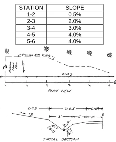
environmental, or aesthetic effects. A sample roadside ditch plan and profile is shown in Figure 7-1. The VDOT Method for Design of Roadside Ditch Linings (Section 7.5.2.2) is recommended for use on minor channels.
Figure 7-1. Sample Roadside Ditch Plan and Profile
It is not recommended to specify non-standard or atypical roadside ditches for highway projects, due to safety and economical concerns. If the designer chooses to specify an atypical ditch section, the designer should minimize its use to the greatest extent
possible. Where the volume, flow, or other considerations dictate enlarging or deepening the roadside ditch or otherwise deviating from the standard designs, careful consideration must be given to the following:⃰
⃰
• Using an enclosed drainage system, where economically feasible, in order to eliminate⃰ the need for the non-standard or atypical roadside ditch or channel
• Minimizing the size and depth of the proposed non-standard or atypical roadside ditch or channel
• Flattening the front slope (the slope adjacent to the highway shoulder) of the
non-standard or atypical roadside ditch or channel. Where right of way is available, or can reasonably be obtained, the front slope of the non-standard or atypical roadside ditch or channel should be no steeper than the front slope of the standard roadside ditch for the specific roadway classification involved
• Locating necessary non-standard or atypical roadside ditches or channels as far from the proposed highway shoulder as the existing or proposed right of way will reasonably allow
7.3.4
Major Channels
Major channels may be within or outside the highway right-of-way. The same design criteria apply as for minor channels. Conveyance is usually based on the 10-year storm but may be greater based upon risk. Erosive protection is based on the 2-year storm. Major channels are usually trapezoidal in cross section. One foot or more of freeboard is recommended for larger channels where the consequences of overtopping are significant. The consequences of failure are usually more severe for major channels; therefore, a higher level of engineering analysis and design is usually justified for major channels.
7.3.5
Natural Channels
The hydraulic effects of floodplain encroachments should be evaluated over a full range of frequency-based peak discharges from the 2-year through the 500-year recurrence intervals on any major highway facility, as deemed necessary by the Department. The hydrologic and hydraulic analysis procedure and required documentation for such situations are more fully described in Chapter 12, Bridge and Structure Hydraulics. If the floodplain encroachment is located in a FEMA or other officially delineated
floodplain, no increase in the established natural 100-yr. flood level will be permitted either up or downstream. It should be noted that the Department’s criteria is more stringent than FEMA’s in this instance. In situations where no FEMA or other officially delineated floodplain exists, it will be acceptable to increase the level of the 100-yr flood event not to exceed one foot up or downstream, provided such increase does not
adversely impact adjacent properties, buildings, etc. If an increase in the 100-yr flood level will cause such adverse impact then no increase shall be permitted. The
Department’s State Hydraulics Engineer must approve exceptions to either of the above criteria.
⃰
If relocation of a stream channel is unavoidable, the cross-sectional shape, meander, pattern, roughness, sediment transport, and slope should conform to the existing conditions as far as practical. Some means of energy dissipation may be necessary when existing conditions cannot be duplicated.
Streambank stabilization should be provided when appropriate, because of any stream disturbance such as encroachment and should include both upstream and downstream banks as well as the local site.
Relocation of major streams is complex, and special expertise in river mechanics engineering and appropriate natural channel and/or stream restoration design may be necessary.
7.4
Design Concepts
7.4.1
Minor Channels (Roadside Ditches)
7.4.1.1 General
Design discharges (peak flows) should be determined by the Rational Method as defined in Chapter 6, Hydrology.
Velocity should be based on normal depth computed using Manning’s equation.
Manning's equation requires information on the ditch geometry, such as side slopes, the longitudinal grade, and the appropriate Manning’s n-value.
Ditch side slopes should not exceed the angle of repose of the soil and/or lining and should usually be 2H:1V or flatter. See Section 7.4.6 for further discussion on channel linings. Figure 7-1 shows a sample plan and profile for a roadside ditch.
7.4.1.2 Design Considerations
Roadside ditch design involves both capacity and erosion resistance. A trial-and-error process may be necessary to obtain the optimum design. More information on roadside ditch design procedures is contained in Section 7.5.
The VDOT method for design of roadside ditch linings is recommended for use on minor channels. Consideration should be given to ditch bends, steep slopes, and composite linings, which are further defined in Section 7.4.6, HEC-11, and HEC-15. The riprap design procedures described in HEC-15 are for minor channels having a design discharge of 50 cfs or less. When the design discharge exceeds 50 cfs, the design procedures presented in HEC-11 should be followed for riprap-lined channels. HEC-15 may be used for design of larger channels with linings other than riprap.
Except where severe right-of-way limitations exist, a minimum of 5’ is to be provided between the end of the cut slope round-off and the front slope of a berm ditch.
Additional right-of-way is to be obtained for construction and maintenance of the berm ditch.⃰
Except where severe right of way limitations exist, a minimum of 5’ is to be provided between the toe of the fill slope and the front slope of a toe ditch. Additional right of way is to be obtained for construction and maintenance of the ditch.
⃰
7.4.2
Major Channels
7.4.2.1 General
Design analysis of both natural and artificial channels proceeds according to the basic principles of open channel flow (see Chow, 1959*; Henderson, 1966). The basic
principles of fluid mechanics, continuity, momentum, and energy can be applied to open channel flow with the additional complication that the position of the free surface is usually one of the unknown variables. The determination of this unknown is one of the principal problems of open channel flow analysis and it depends on quantification of the flow resistance. Natural channels display a much wider range of roughness values than do artificial channels.
7.4.2.2 Flow Classifications
The classifications of open channel flow are summarized as follows:
Steady Flow (Rate of flow remains constant with time)
1. Uniform Flow (Velocity and depth of flow remain constant over length) 2. Non-uniform Flow (Velocity and depth of flow vary over length)
• Gradually Varied Flow
• Rapidly Varied Flow
Unsteady Flow (Rate of flow varies with time)
1. Unsteady Uniform Flow (rare) 2. Unsteady Non-uniform Flow
• Gradually Varied Unsteady Flow
• Rapidly Varied Unsteady Flow
The steady uniform flow class and the steady non-uniform flow class are the most common types of flow treated in highway engineering hydraulics. However, uniform flow is rare in natural channels.
7.4.3
Natural Channels
7.4.3.1 Stream Morphology
7.4.3.1.1 Introduction
The form assumed by a natural stream, which includes its cross-sectional geometry as well as its plan-form, is a function of many variables for which cause-and-effect
relationships are difficult to establish. The stream may be graded or in equilibrium with
*
respect to long time periods, which means that on the average it discharges the same amount of sediment that it receives, although there may be short-term adjustments in its bed-forms in response to flood flows. On the other hand, the stream reach of interest may be aggrading or degrading as a result of deposition or scour in the reach,
respectively. The plan-form of the stream may be straight, braided, or meandering. These complexities of stream morphology can be assessed by inspecting aerial photographs and topographic maps for changes in slope, width, depth, meander form and bank erosion with time.
A qualitative assessment of the river response to proposed highway facilities is possible through a thorough knowledge of river mechanics and accumulation of engineering experience. The FHWA publications "Stream Stability at Highway Structures" (HEC-20) and “River Engineering for Highway Encroachments” (HDS-6) provide additional and more detailed information on making such assessments . Both publications can be accessed and/or downloaded from the FHWA’s Internet web site at
http://www.fhwa.dot.gov/engineering/hydraulics/library_listing.cfm .*
7.4.4
Channel Analysis
7.4.4.1 General
The hydraulic analysis of a channel determines the depth and velocity at which a given discharge will flow in a channel of known geometry, roughness and slope. The depth and velocity of flow are necessary for the design or analysis of channel linings and highway drainage structures.
Two methods are commonly used in hydraulic analysis of open channels. The single-section method is a simple application of Manning's equation to determine tailwater rating curves for culverts or to analyze other situations in which uniform or nearly uniform flow conditions can be assumed.
The step-backwater method is used to compute the complete water surface profile in a stream reach to evaluate the unrestricted water surface elevations for bridge hydraulic design or to analyze other gradually varied flow problems in streams.
A. Where the 100-year discharge for a particular site is less than 500 cfs, the site is generally considered to be a minor drainage installation. A single cross section analysis, using nomographs and charts, usually provides an
acceptable level of hydraulic analysis. Documentation requirements are satisfied by supplying all requested information on VDOT standard hydraulic computation forms.
*
B. Where the 100-year discharge for a particular site is 500 cfs or more, the site is generally considered to be a major drainage installation. The method of hydraulic analysis and the level of documentation must conform to hydrology analysis (H&HA) outline provided in Chapter 12, Bridge and Structure
Hydraulics. This type of analysis often requires water surface profile calculations such as those provided by the HEC-2, HEC-RAS, or WSPRO computer models. However, other methods of analysis, which provide the necessary data for proper documentation, may be approved for use. The single-section method will generally yield less reliable results than the step-backwater method because it requires more judgment and assumptions. In many situations, however, the single-section method is all that is justified. In minor drainage channels such as roadside ditches, the single section method is adequate, except in the case of special design channels or critical locations.
The step-backwater method should be used for important major channels, where an accurate definition of the water surface profile is needed. The basic principles of open channel hydraulics are applicable to all drainage channels, as well as culverts and storm drains. The variable is the level of detail required in design, which depends on the risks of damage or loss of life caused by a failure of the facility.
7.4.4.2 Equations
The following equations are those most commonly used to analyze open channel flow. The detailed use of these equations in analyzing open channel hydraulics is discussed in Section 7.5.
7.4.4.2.1 Specific Energy
Specific energy (E) is defined as the energy head relative to the channel bottom. If the channel slope is less than 10 percent and the streamlines are nearly straight and
parallel (so that the hydrostatic assumption holds), the specific energy (E) becomes the sum of the depth and velocity head:
2
V E = d+
2g
α (7.1)
Where:
d = Depth of flow, ft
α = Velocity distribution coefficient (see Equation 7.2) v = Mean velocity, fps
g = Gravitational acceleration, 32.2 ft/s2
When specific energy is plotted against depth of flow, a curve with a minimum specific energy results, as shown in Figure 7-2. At the minimum specific energy, the depth is called critical depth. Depths above critical depth are subcritical, and below critical depth
are supercritical. The velocity distribution coefficient is usually assumed to have a value of one for turbulent flow in prismatic channels but may be significantly different than one in natural channels.
Note: y = d in Equation 7.1
Figure 7-2. Specific Energy Diagram for Rectangular Channels
7.4.4.2.2 Velocity Distribution Coefficient
Due to the presence of a free surface and due to friction along the channel boundary, the velocities in a channel are not uniformly distributed across the channel cross section. Because of non-uniform distribution of velocities in a channel section, the velocity head of an open channel is usually greater than the average velocity head computed as (Q/At)2/2g. A weighted average value of the velocity head is obtained by
multiplying the average velocity head, above, by a velocity distribution coefficient (α) defined as: 3 n i 2 i=1 i 3 t 2 t K A = K A α
∑
(7.2) Where:Ki = Conveyance in subsection (see Equation 7.8)
Kt = Total conveyance in section (see Equation 7.8)
Ai = Cross-sectional area of subsection, ft2
At = Total cross-sectional area of section, ft2
n* = Number of subsections
*
7.4.4.2.3 Total Energy Head
The total energy head is the specific energy head plus the elevation of the channel bottom with respect to some datum. A plot of the energy head from one cross section to the next defines the energy grade line.
7.4.4.2.4 Froude Number
The Froude number (Fr) is an important dimensionless parameter in open channel flow.
It represents the ratio of inertial forces to gravitational forces and is defined as:
r D V F = gH α (7.3) Where:
α = Velocity distribution coefficient V = Mean velocity = Q/A, fps
g = Gravitional acceleration*, 32.2 ft/s2
HD = Hydraulic depth =
A T
, ft
(For rectangular channels the hydraulic depth is equal to the flow depth.)
A = Cross-sectional area of flow, ft2
T = Channel top width at the water surface, ft Q = Discharge, cfs
This expression for Froude number applies to channel flow at any cross section. The Froude number is useful in determining the flow regime for water surface profiles.
• Fr < 1, Subcritical Flow • Fr = 1, Critical Flow • Fr > 1, Supercritical Flow 7.4.4.2.5 Critical Flow
Critical flow occurs when the specific energy is a minimum for a given flow rate (see Figure 7-2). The variation of specific energy with depth at a constant discharge shows a minimum in the specific energy at a depth called critical depth at which the Froude number has a value of one. Critical depth is the depth of maximum discharge when the
*
specific energy is held constant. During critical flow the velocity head is equal to one-half of the hydraulic depth. The general expression for flow at critical depth is:
2 3 Q A = g T α (7.4) Where:
α = Velocity distribution coefficient Q = Discharge, cfs
g = Gravitational acceleration, 32.2 ft/s2 A = Cross-sectional area of flow, ft2
T = Channel top width at the water surface, ft
When flow is at critical depth, Equation 7.4 must be satisfied, regardless of the shape of the channel.
7.4.4.2.6 Subcritical Flow
Depths greater than critical occur in subcritical flow. The Froude number is less than one for subcritical flow. In this state of flow, small water surface disturbances can travel both upstream and downstream, and the control is always located downstream.
7.4.4.2.7 Supercritical Flow
Depths less than critical depth occur in supercritical flow. The Froude number is greater than one. Small water surface disturbances are always swept downstream in
supercritical flow, and the location of the flow control is always upstream.
7.4.4.2.8 Continuity Equation
The continuity equation is the statement of conservation of mass in fluid mechanics. For the special case of one-dimensional, steady flow of an incompressible fluid, it assumes the simple form:
Q = A1V1 = A2V2* (7.5)
Where:
Q = Discharge, cfs
A = Cross-sectional area of flow, ft2
V = Mean cross-sectional velocity, fps (which is perpendicular to the cross section)
Subscripts 1 and 2 refer to successive cross sections along the flow path.
*
7.4.4.2.9 Manning's Equation
For a given depth of flow in an open channel with a steady, uniform flow, the mean velocity (V) can be computed using Manning's equation:
2 1 3 2
1.486 V = R S
n (7.6)
Where:
V = Velocity, fps
n = Manning's roughness coefficient R = Hydraulic radius = A/P, ft
A = Flow area, ft2
P = Wetted perimeter, ft
S = Slope of the energy grade line, ft/ft
The selection of Manning's n is generally based on observation; however, considerable experience is essential in selecting appropriate n-values. The selection of Manning's n is discussed in Section 7.4.4.3.2. The range of n-values for various types of channels and floodplains is given in Appendix 7D-1 and 7D-2.
The continuity equation can be combined with Manning's equation to obtain the steady, uniform flow discharge as:
2 1 3 2
1.486 Q AR S
n
= (7.7)
For a given channel geometry, slope, roughness, and a specified discharge (Q), a unique value of depth occurs in steady, uniform flow. It is called normal depth. At normal depth, the slope of the energy grade line, the hydraulic grade line, and the channel slope are the same. Normal depth is computed from Equation 7.7 by expressing the area and hydraulic radius in terms of depth. The resulting equation may require a trial-and-error solution. See Section 7.5 for a more detailed discussion of the computation of normal depth.
If normal depth is greater than critical depth, the channel slope is classified as a mild slope. On a steep slope, the normal depth is less than the critical depth. Thus, uniform flow is subcritical on a mild slope and supercritical on a steep slope.
7.4.4.2.10 Conveyance
In channel analysis, it is often convenient to group the channel properties in a single term called the channel conveyance (K):
2 3 1.486 K AR n = (7.8)
Then Equation 7.7 can be written as:
1 2
Q=KS (7.9)
The conveyance represents the carrying capacity of a stream cross-section based upon its geometry and roughness characteristics alone and is independent of the streambed slope.
The concept of channel conveyance is useful when computing the distribution of overbank flood flows in the stream cross-section and the flow distribution through the opening in a proposed stream crossing. It is also used to determine the velocity distribution coefficient (α).
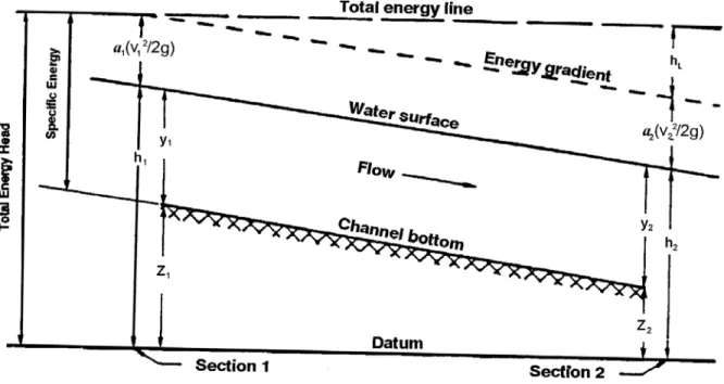
7.4.4.2.11 Energy Equation
The energy equation (Bernoulli's Equation) expresses conservation of energy in open channel flow defined as energy per unit weight of fluid. This dimensions of length is called energy head. The energy head is composed of potential energy head (elevation head), pressure head, and kinetic energy head (velocity head). These energy heads are scalar quantities, the sum of which gives the total energy head at any cross section. Written between an upstream open channel cross section designated 1 and a
downstream cross section designated 2, the energy equation is:
2 2
1 2
1 1 2 2 L
V V
h h h
2g 2g
+ α = + α + (7.10)
Where:
h1 = Upstream water surface elevation, ft.
h2 = Downstream water surface elevation, ft. α = Velocity distribution coefficient
V = Mean velocity, fps
hL = Head loss due to local cross-sectional changes (minor loss) plus
friction loss, ft
The stage, h, is the sum of the elevation head (z) at the channel bed and the pressure head, or depth of flow (y); i.e., h = z+y. The terms in the energy equation are illustrated graphically in Figure 7-3. The energy equation states that the total energy head at an upstream cross section is equal to the energy head at a downstream section plus energy head losses between two consecutive sections. The energy equation can only be applied between two cross sections at which the streamlines are nearly straight and parallel so that vertical acceleration can be neglected.
Figure 7-3. Terms in the Energy Equation
7.4.4.3 Hydraulic Representation of Channels
The following sections describe the data needed to apply Manning's equation to the analysis of open channels.
7.4.4.3.1 Cross Sections
The cross-sectional geometry of streams is defined by coordinates of lateral distance and ground elevation, which locate individual ground points. Individual cross sections are taken normal to the flow direction along a single straight line where possible, but in wide floodplains or bends it may be necessary to use intersecting straight lines to form a section; i.e., a "dog-leg" section. It is especially important to make a plot of the cross section to reveal any inconsistencies or errors.
Cross sections should be located to be representative of the sub-reaches between them. Stream locations with major breaks in bed profile, abrupt charges in roughness or shape, control sections such as free overfalls, bends and contractions, or other abrupt changes in channel slope or conveyance will require cross sections taken at shorter intervals in order to better model the changes in conveyance.
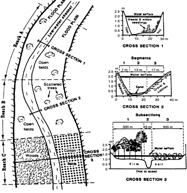
Cross sections should be subdivided with vertical boundaries where there are abrupt lateral changes in geometry and/or roughness as in the case of overbank flows. The conveyances of each subsection are computed separately to determine the flow
distribution and α, and are then added to determine the total flow conveyance. The subsection divisions must be chosen carefully so that the distribution of flow or
conveyance is nearly uniform in each subsection (Davidian, 1984). Selection of cross sections and vertical subdivision of a cross section are shown in Figure 7-4.
Figure 7-4. Hypothetical Cross Section Showing Reaches, Segments, and Subsections Used in Assigning n-Values
7.4.4.3.2 Manning’s n-Value Selection
Manning's n is affected by many factors and its selection, especially in natural channels depends heavily on engineering experience. Photographs of channels and flood plains, for which the discharge has been measured, and Manning's n has been calculated, are very useful (see Arcement and Schneider, 1984; Barnes, 1978). For situations lying outside the engineer's experience, a more regimented approach is presented (Arcement and Schneider, 1984). Once the Manning's n-values have been selected, it is highly recommended that they be verified or calibrated with historical highwater marks and/or gaged stream flow data.
Manning's n-values for artificial channels are more easily obtained than for natural stream channels. Refer to Appendix 7D-1 and 7D-2 for typical n-values for both man-made and natural stream channels.
7.4.4.3.3 Calibration
For major channel analyses in existing channels, the equations should be calibrated with historical highwater marks and/or gaged stream flow data to ensure that they accurately represent local channel conditions. The following parameters, in order of preference, should be used for calibration: Manning's n, slope, discharge, and cross section. Proper calibration is essential if accurate results are to be obtained.
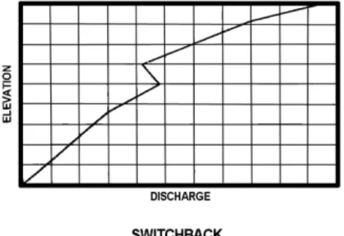
7.4.4.3.4 Switchback Phenomenon
If the cross section is improperly subdivided, the mathematics of Manning's equation causes a switchback. A switchback results when the calculated discharge decreases with an associated increase in elevation. This occurs when, with a minor increase in water depth, there is a large increase of wetted perimeter. Simultaneously, there is a corresponding small increase in cross-sectional area, which causes a net decrease in the hydraulic radius from the value computed for a lesser water depth. With the
combination of the lower hydraulic radius and the slightly larger cross-sectional area, a discharge is computed which is lower than the discharge based upon the lower water depth. More subdivisions within such cross sections should be used, and the divisions should be based on both vegetation and geometry, in order to avoid the switchback error. Figure 7-5 depicts an example of the switchback phenomenon.
7.4.4.4 Single-Section Analysis
The single-section analysis method (slope-area method) is simply a solution of
Manning's equation for the normal depth of flow, given the discharge and channel cross section properties including geometry, slope and roughness. It implicitly assumes the existence of steady, uniform flow; however, uniform flow rarely exists in either man-made or natural channels. Nevertheless, the single-section method is often used to design man-made channels for uniform flow as a first approximation, and to develop a stage-discharge rating curve in a natural channel for tailwater determination at a culvert or storm drain outlet. The single-section analysis method is used in the VDOT method for design of roadside ditch linings.
A stage-discharge rating curve is a graphical relationship of stream flow depth or elevation versus discharge at a specific point on a channel. This relationship should cover a range of discharges up to at least the base (100-year) flood. The stage-discharge curve procedure is discussed in Section 7.5.3.1.
Alternatively, a graphical technique such as those given in the appendices can be used for trapezoidal and prismatic channels. The best approach, especially in the case of natural channels, is to use a computer program such as FEMA's "Quick-2" software package.
In natural channels, the transverse variation of velocity in any cross section is a function of subsection geometry and roughness and may vary considerably from one stage and discharge to another. It is important to know this variation for purposes of designing erosion control measures and locating relief openings such as in highway fills. The single-section method can be used by dividing the cross section into subsections of relatively uniform roughness and geometry. It is assumed that the energy grade line slope is the same across the cross section so that the total conveyance (Kt)of the cross
section is the sum of the subsection conveyances. The total discharge is then KtS1/2 and
the discharge in each subsection is proportional to its conveyance. The velocity in each subsection is obtained from the continuity equation, V = Q/A.
7.4.4.5 Water Surface Profile Analysis
The step-backwater analysis is useful for determining unrestricted water surface profiles where a highway crossing or encroachment is planned, and for analyzing how far
upstream the water surface elevations would be affected. Because the calculations involved in this analysis are tedious and repetitive, it is recommended that a computer program such as the Corps of Engineers HEC-RAS model be used.
7.4.4.5.1 Water Surface Profile Methodology
When uniform flow cannot be reasonably assumed and, therefore, a single cross
section cannot represent the channel segment, then an energy balance method must be used to compute the water surface profile (elevation). The energy equation is used in computing the water surface profile.
The method requires definition of the geometry and roughness of each cross section as discussed previously. Manning's n values can vary both horizontally and vertically across the section. Expansion and contraction head loss coefficients, variable main channel and overbank flow lengths and the method of averaging the slope of the energy grade line can all be specified.
The energy equation is derived from Equation 7.10 in Section 7.4.4.2.11.
2 2
1 2
1 1 1 2 2 2 L
V V
d z d z h
2g 2g
+ α + = + α + + (7.11)
Where:
d = Depth of flow, ft V = Mean velocity, fps z = Elevation of flow line, ft hL = Total head loss, ft
α = Velocity distribution coefficient*
Equation 7.11 shows that the total head at Section 1 is equal to the total head at
Section 2 and the energy (head) losses. Total energy losses include friction and minor losses.
L f o
h =h +h (7.12)
Where:
hL = Total head losses, ft.
hf = Friction loss, ft.
ho = Summation of minor losses, ft.
In most simple water surface profile calculations, minor losses are ignored; therefore,hL
is assumed to be equal to hf.
f A
h =LS (7.13)
Where:
L = Length of channel segment, ft.
SA = Average energy slope of channel segment, ft./ft.
1 2 A S S S 2 + = (7.14) * Rev 9/09
Where:
S1 = Energy slope at Section 1, ft./ft.
S2 = Energy slope at Section 2, ft./ft.
The energy slope at a given cross section is computed using Equation 7.15 and is shown graphically in Figure 7-6.
4 3
2 2 2
Q n S
2.25R A
= (7.15)
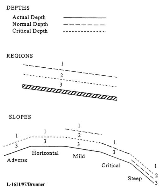
Figure 7-6. Energy Slope between Two Channel Sections 7.4.4.5.2 Classifications of Backwater Profiles
Figure 7-7 shows the notation for classifying water surface profiles and Figure 7-8 shows the types of possible flow profiles. Figure 7-7 and Figure 7-8 are from the USACE’s Gary Brunner.
7.4.4.5.3 Water Surface Profile Computations
The references (Davidian, 1984 and USACE, 1986) are valuable sources of guidance on the practical application of the step-backwater method to roadway drainage
problems involving open channels. These references contain guidance on cross section determination, location and spacing, and stream reach determination. The reference (USACE, 1986) investigates the accuracy and reliability of water surface profiles related to n-value determination and the survey or mapping technology used to determine the cross section coordinate geometry.
7.4.5
Water and Sediment Routing
Water and sediment routing is a complex phenomenon, and a detailed discussion is beyond the scope of this manual. Information may be found in documentation of the BRI-STARS (Bridge Stream Tube Model for Alluvial River Simulation) Computer Model, (Molinas, 2000*). The model is semi-two dimensional, and both energy and momentum functions are incorporated so that the water surface profile computation can be carried out through combinations of subcritical and supercritical flows without interruption. Another computer model for sediment routing is the Corps of Engineers HEC-6, "Scour and Deposition in Rivers and Reservoirs." (legacy software)
7.4.6
Ditch and Channel Protection
A significant means of reducing erosion associated with roadways is through the use of properly designed ditches and ditch lining. Linings may be flexible such as vegetation, synthetic material; or riprap or linings may be rigid such as concrete. Erosion resistant vegetation should be used whenever possible and may in some locations require the use of either a temporary protective covering (VDOT Standard EC-2) or a permanent soil stabilization mat (VDOT Standard EC-3, Type A, or Type B). Flexible linings are generally less expensive than rigid linings and permit infiltration and filtering of
pollutants. Flexible linings provide a lower flow capacity for a given cross-sectional area when compared to rigid linings. They also have correspondingly lower velocities than rigid linings.
Rigid linings are used on steep grades due to high velocities and may be used for areas where channel width is restricted and the higher flow capacity is needed. Rigid
channels require channel protection or energy dissipation at the termination point to prevent scour due to the high outlet velocities. Rigid linings can be damaged or destroyed due to flow undercutting the lining at bends, joints or intersecting ditches where the flow is not contained within the lining. The design of channels with rigid lining should provide any design details that are needed to protect the undercutting of the lining and preserve the integrity of the ditch.
*
Two methods are commonly applied to determine whether a channel is stable from an erosion standpoint: Permissible Velocity and Tractive Force. These methods are described in the following sections.
7.4.6.1 Permissible Velocity
Using the permissible velocity approach, the channel is assumed to be stable if the mean velocity is lower than the maximum permissible velocity. The application of the permissible velocity method is quite simple. The Manning equation is used to compute the flow velocity in the channel for the design storm. The flow velocity is then compared with the maximum permissible velocity for the channel bed and bank soils and the lining material.
If the computed velocity is less than the maximum permissible velocity, the channel should be stable. Corrections to the maximum permissible velocity may be applied based on flow depth and channel sinuosity.
The maximum permissible velocity (MPV) in a channel varies with the channel bed material and with the material being transported by the water. Clear water is the most erosive, and therefore its MPVs are the lowest for a given bed material (see Appendix 7D-6). When the water is transporting fine silts, the MPV is up to 100 percent higher than for clear water. For this reason, clear water being released from a settling facility such as a detention pond is often called “hungry water.”
For water carrying a courser material such as sand and gravel, the MPV may be higher or lower than for clear water. For this situation, refer to Appendix 7D-6 to obtain the MPV for the given channel bed material.
While the permissible velocity method is widely used, the tractive force (permissible shear) method provides a more physically based and realistic model for particle
detachment and erosion processes (FHWA's HEC-15 , “Design of Roadside Channels with Flexible Linings”). It is recommended that the permissible velocity method be used for roadside ditches and that the tractive force method be used for major channel
analyses.
7.4.6.2 Tractive Force
The Tractive Force Method takes into account the physical factors of bed material, channel geometry, depth, and velocity of flow. The method is confined to non-cohesive materials for which the permissible tractive force is related to particle size and shape and the sediment load in the water. Particle diameters are based on the equivalent spherical volume and assume 75 percent of the mass is smaller by weight (D75). In the
absence of a gradation curve, it may be assumed that the D75 stone size is equal to
1.96 times the D50 stone size.
The material on the side slope may establish the limiting condition for permissible tractive force, rather than the material on the bed. The resistance to movement of the material on the side slope is reduced by the downward sliding force due to gravity. The
ratio of critical shear on the side slope to critical shear on the bottom is expressed as factor K1.
Note: K1 in HEC-11 is the same variable as K2 in HEC-15. 2
1 2
sin K = 1
sin
θ −
φ (7.16)
Where:
θ = Side slope angle (measured from the horizontal), degrees
φ = Natural angle of repose of material under consideration (measured from the horizontal), deg.
Note: The descriptions for θ and φ (above) are reversed in Appendix 7E-8.
(shown one way in HEC-11 and the other way in HEC-15)*
The angles of repose for various sizes of non-cohesive materials can be determined from Appendix 7E-1.
The permissible tractive force for various non-cohesive soils is obtained from Appendix 7E-2. Appendix 7E-3 can be used to estimate the permissible tractive force for
cohesive soils.
The average tractive force formula is:
o = 62.4RSo
τ (7.17)
Where:
τo = Average tractive force, lbs/ft2
R = Hydraulic radius, ft. So = Channel slope, ft/ft.
In channels whose width (B) to depth (d) ratio is 10 or more, the depth of flow (d) may be substituted for R, thus obtaining the maximum tractive force on the channel bed.
max = 62.4dSo
τ (7.18)
Where:
*
d = Depth of flow, ft
A convenient form that can be used for manually performing this computation is found in Appendix 7B-3.
7.4.6.3 Geotextile Channel Linings
Geotextile materials designated as Standard EC-3 (Type A and B) Soil Stabilization Mat are used for protective linings in ditches. Standard EC-3 Soil Stabilization Mat is
intended to be used as a protective ditch lining material to be applied when the design velocity exceeds the allowable velocity for Standard EC-2 (i.e., jute mesh).
When the design velocity exceeds the allowable velocity for Standard EC-3, a paved (or riprap) lining is required.
The Standard EC-3 (Type C) Soil Stabilization Mat may be used as a protective slope lining for dry cut or fill slopes and wet cut slopes to stabilize the slope on which
vegetation is being established. (See VDOT Road and Bridge Standards)
7.4.6.3.1 Design Criteria, Geotextile Linings
Standard EC-3 Type A is to be employed where the 2-year design velocity in the ditch does not exceed 7* feet per second (fps).
Standard EC-3 Type B is to be employed where the 2-year design velocity does not exceed 10 fps.
A Manning’s n-value of 0.05 should be used with Standard EC-3.
Typically, the use of Standard EC-3 Type A should begin at the point where the flow velocity exceeds 4 fps (velocity is assumed to be for flow in an EC-2 lined channel) and change to EC-3, Type B at the appropriate point, until the design velocity exceeds 10 fps or until the velocity decreases so that the use of a ditch lining can be discontinued.
Table 7-1. PROTECTIVE LININGS FOR DITCHES AND CHANNELS
Type of Lining Mannings “n” Value (Default)
Maximum Allowable Velocity (fps)
Bare Earth 0.03 Varies
VDOT EC-2 0.05 4.0
VDOT EC-3 Type A 0.05 7.0
*
VDOT EC-3 Type B 0.05 10.0
Concrete 0.015 NA
VDOT Riprap 0.04-0.045 Based on Sheer Stress
7.4.6.3.2 Paved Flumes⃰
Due to the substantial number of failures and continual maintenance problems
associated with PG-4 flumes on fill slopes, it is recommended that flumes not be used on fill slopes.
In lieu of paved fumes, it is recommended that the appropriate type of drop inlet and pipe be used in all possible situations. For design considerations of pipe on steep slopes see Section 9.4.8.7 of the Drainage Manual.
To a lesser degree, similar problems and concerns have been noted with paved flumes in cut sections. The alternatives for paved flumes in cut sections are usually very limited unless the cut is of a shallow depth.
When design situations involve the apparent need for paved flumes, the Drainage Designer should explore all feasible alternatives to develop a design that will address both constructability and future maintenance concerns.
7.4.6.4 Riprap
Riprap is defined as a blanket of well-graded stone used to counteract the effects of erosion or scouring on channels, ditches, embankments, jetties, shorelines, and bridge substructure members such as abutments and piers. Riprap is usually described in terms of the size and/or weight of the stone whose volume makes up approximately 50 percent of the total mass. The size of the 50 percent stone is measured in terms of its equivalent mean spherical diameter (MSD) and is referred to as the stone’s D50. The
weight of the 50 percent stone is referred to by its W50. The Department has six
standard riprap classifications whose 50 percent stone size and weights and recommended blanket thickness (T) are tabulated in Appendix 7D-3.
Additional information on VDOT standard riprap may be found in the Department's Road and Bridge Specifications.
The designer shall specify on the plans the type of Riprap and the dimensions (length, width and depth) for placement. The quantity shall be computed using two (2) tons per
⃰
cubic yard (148 lbs. per cu. ft.) for plan estimating purposes, unless otherwise specified by the District Administrator.
The following general note is to be copied on the plans when riprap is specified. “The proposed riprap may be omitted by the Engineer if the slope upon which the plans designate riprap to be placed is found to meet the following criteria: The slope designated for placement of riprap is
comprised of solid rock or closely consolidated boulders with soundness, size and weight equal to or exceed the specifications for the proposed riprap. If the slope is found to be comprised of material, which is coarser than the bedding aggregate filter blanket specified on the plans, the aggregate filter blanket may be deleted by the Engineer.”
7.4.6.4.1 Riprap Dimensions and Weights
Appendix 7D-4 may be used as a guide to match certain rock dimensions to equivalent weights. This table is not to be used for acceptance or rejection of riprap material. The approximate percentages of voids for all VDOT standard riprap classes is 25 percent for the estimation of quantities.
7.4.6.4.2 Soils Survey
A soil survey is to be conducted through areas where a channel change is proposed and through embankment areas where riprap may be required. The plans or profile rolls for the regular soil survey will show the location of channel changes and the location where riprap will be required on the fill section.
Borings along the proposed channel change are to be taken at sufficient intervals to determine the type of material encountered along the slopes and in the bottom of the channel.
The borings made in the cut sections or in the borrow pits for construction of the fills are adequate to determine the type of material used in the fills. The test results on the material used in embankments or along channel changes where riprap is required should include the plastic and liquid limits of the minus No. 40 sieve and the grading or particle size of the total sample. This information should be submitted in the regular soil survey report.
The Project Inspector will visually examine the slope upon which the plans designate riprap to be placed. If the slope material appears coarser than the bedding aggregate specified the Project Inspector is to notify the District Material Engineer, through normal channels, for a more detailed investigation to determine the actual need for the bedding. If the slope is comprised of solid rock or closely consolidated boulders with soundness, size and weight equal to or exceeding the specifications for the proposed riprap, then the riprap may be deleted by the District Construction Engineer.
The quantities will be field adjusted, using the supplier’s stone weight and the applicable percent of voids for the type or class of material used, to obtain the actual quantity.
7.4.6.4.3 Riprap Bedding
Riprap shall be placedover an appropriate bedding material consisting of a geotextile and aggregate cushion layer in accordance with the following guidelines*
• In the case of Class AI, I, and II riprap, the aggregate cushion is not required.
• In the case of Class III, Type I, and Type II riprap, the an intermediate aggregate cushion layer will be required which consists of a material of a size, gradation, and thickness as recommended by the Materials Division
The geotextile may only be omitted under the conditions discussed above or with the approval of the District Materials Engineer or District Drainage Engineer.
7.4.6.4.4 Major Channels
Riprap is often used as slope protection for natural or man-made stream channels. The need for such slope protection is predicated on the fact that the native soil material or fill material may be displaced by design flows in the channel. The first step in the design process is to determine whether or not the fill or native material will be displaced. The tractive force method is usually employed to make this determination.
7.4.6.4.5 Minor Channels
VDOT normally does not permit the use of standard riprap for linings in standard roadside or median ditches due to its size and normal blanket thickness reducing the ditch cross section. In addition, hand placement, as opposed to end dumping, would probably be necessary in small channels. There are, however, situations in which the smaller riprap sizes such as Class AI and I may be used to good advantage where special design small trapezoidal ditches such as those connecting culvert cross drains, outfalls, or the discharge point of standard design ditches, are required. In such
situations, the Department requires that the riprap be sized in accordance with procedures presented in HEC-15. When riprap is used to line minor channels, the design for the channel cross section should allow for the thickness of the riprap and bedding layers without reducing the available flow section.
*
7.5
Design Procedures and Sample Problems
The following design procedures and examples pertain to minor channels, major
channels, and natural channels. The procedures are similar, but become more detailed for the larger channel projects.
7.5.1
Documentation Requirements
These items establish a minimum requirement for all channels except roadside ditches. Also, see Chapter 3, Documentation.* The following items used in the design or
analysis should be included in the documentation file:
• Hydrology and stage discharge curves for the design, check floods and any historical water surface elevation(s)
• Cross section(s) used in the design water surface determinations and their locations
• Roughness coefficient assignments (n-values)
• Information on the method used for design water surface determinations
• Observed highwater, dates and discharges
• Channel velocity measurements or estimates and locations
• Water surface profiles through the reach for the design, check floods and any historical floods
• Design or analysis of materials proposed for the channel bed and banks;
• Energy dissipation calculations and designs
• Copies of all computer analyses.
7.5.2
Roadside Ditches and Minor Channels
7.5.2.1 Roadside Ditch and Minor Channel Design Procedure
The following six basic design steps are normally applicable to minor channel design projects:
Step 1: Establish a roadside plan
A. Collect available site data
B. Obtain or prepare existing and proposed plan-profile layout including highway, culverts, bridges, etc.
*
C. Determine and plot on the plan the locations of natural basin divides and roadside ditch outlets and perform the layout of the proposed roadside ditches to minimize diversion flow lengths
An example of a roadside ditch plan/profile is shown in Figure 7-1.
Step 2: Obtain or establish cross section and data
A. Provide ditch depth adequate to drain the subbase and minimize freeze-thaw effects using the standard underdrain outfall requirements that are appropriate for the project
B. Choose ditch side slopes based on geometric design criteria including safety, economics, soil, aesthetics and access
C. Establish bottom width of trapezoidal ditch
D. Identify features which may restrict cross section design:
• Right-of-way limits
• Trees or other environmentally-sensitive areas
• Utilities
• Existing drainage facilities
Step 3: Determine initial ditch grades
A. Plot initial grades on plan-profile layout. (The roadside ditch grade in cut is usually controlled by the grade of the highway.)
B. Provide desirable minimum grade of 0.5* percent
C. Consider influence of type of lining on grade
D. Where possible, avoid features which may influence or restrict grade, such as utility locations
Step 4: Check flow capacities and adjust as necessary
A. Compute the design discharge at the downstream end of a ditch segment (See Chapter 6, Hydrology)
B. Set preliminary values of ditch size, roughness coefficient, and slope
*
C. Determine maximum allowable depth of ditch, including freeboard D. Check flow capacity using Manning’s equation and the single-section
analysis
E. If ditch capacity is inadequate, possible adjustments are as follow:
• Increase bottom width
• Make channel side slopes flatter
• Make channel slope steeper
• Provide smoother channel lining
• Install drop inlets and a parallel storm drain pipe beneath the channel to supplement channel capacity
F. Provide smooth transitions at changes in channel cross sections
G. Provide extra channel storage where needed to replace floodplain storage and/or to reduce peak discharge
Step 5: Determine ditch lining/protection needed
A. Use the VDOT Method – Roadside Ditch Linings (Preferred Method - Section 7.5.2.2), or
B. Use the method of allowable tractive force (HEC-15)
Step 6: Analyze outlet points and downstream effects
A. Identify any adverse impacts such as increased flooding or erosion to downstream properties which may result from one of the following at the channel outlet:
• Increase or decrease in discharge
• Increase in velocity of flow
• Concentration of sheet flow
• Change in outlet water quality
• Diversion of flow from another watershed
B. Mitigate any adverse impacts identified in Step 6A. Possibilities include:
• Enlarge outlet channel and/or install control structures to provide detention of increased runoff in channel
• Install velocity control structures (energy dissipaters)
• Increase capacity and/or improve lining of downstream channel