Virtual Private Networks
Release
Juniper Networks, Junos, Steel-Belted Radius, NetScreen, and ScreenOS are registered trademarks of Juniper Networks, Inc. in the United States and other countries. JunosE is a trademark of Juniper Networks, Inc. All other trademarks, service marks, registered trademarks, or registered service marks are the property of their respective owners.
Juniper Networks assumes no responsibility for any inaccuracies in this document. Juniper Networks reserves the right to change, modify, transfer, or otherwise revise this publication without notice.
Products made or sold by Juniper Networks or components thereof might be covered by one or more of the following patents that are owned by or licensed to Juniper Networks: U.S. Patent Nos. 5,473,599, 5,905,725, 5,909,440, 6,192,051, 6,333,650, 6,359,479, 6,406,312, 6,429,706, 6,459,579, 6,493,347, 6,538,518, 6,538,899, 6,552,918, 6,567,902, 6,578,186, and 6,590,785.
Copyright © 2009, Juniper Networks, Inc. All rights reserved.
Revision History
December 2012—Revision 02
Content subject to change. The information in this document is current as of the date listed in the revision history.
SOFTWARE LICENSE
The terms and conditions for using this software are described in the software license contained in the acknowledgment to your purchase order or, to the extent applicable, to any reseller agreement or end-user purchase agreement executed between you and Juniper Networks. By using this software, you indicate that you understand and agree to be bound by those terms and conditions.
Generally speaking, the software license restricts the manner in which you are permitted to use the software and may contain prohibitions against certain uses. The software license may state conditions under which the license is automatically terminated. You should consult the license for further details.
For complete product documentation, please see the Juniper Networks Website atwww.juniper.net/techpubs. END USER LICENSE AGREEMENT
The Juniper Networks product that is the subject of this technical documentation consists of (or is intended for use with) Juniper Networks software. Use of such software is subject to the terms and conditions of the End User License Agreement (“EULA”) posted at
http://www.juniper.net/support/eula.html. By downloading, installing or using such software, you agree to the terms and conditions of that EULA.
About This Guide . . . xvii
Part 1
Virtual Private Networks
Chapter 1 Internet Protocol Security . . . 3Chapter 2 Public Key Cryptography . . . 35
Chapter 3 Virtual Private Network Guidelines . . . 61
Chapter 4 Site-to-Site Virtual Private Networks . . . 91
Chapter 5 Dialup Virtual Private Networks . . . 169
Chapter 6 Layer 2 Tunneling Protocol . . . 213
Chapter 7 Advanced Virtual Private Network Features . . . 241
Chapter 8 AutoConnect-Virtual Private Networks . . . 331
Part 2
Index
Index . . . 361About This Guide . . . xvii
Document Conventions . . . xviii
Document Feedback . . . xx
Requesting Technical Support . . . xx
Part 1
Virtual Private Networks
Chapter 1 Internet Protocol Security . . . 3Introduction to Virtual Private Networks . . . 3
IPsec Concepts . . . 4 Modes . . . 5 Transport Mode . . . 5 Tunnel Mode . . . 6 Protocols . . . 7 Authentication Header . . . 7
Encapsulating Security Payload . . . 8
Key Management . . . 9 Manual Key . . . 9 AutoKey IKE . . . 9 Key Protection . . . 10 Security Associations . . . 10 Tunnel Negotiation . . . 11 Phase 1 . . . 11
Main and Aggressive Modes . . . 12
Diffie-Hellman Exchange . . . 13
Elliptical Curve Diffie-Hellman . . . 13
Phase 2 . . . 14
Perfect Forward Secrecy . . . 15
Replay Protection . . . 15
IKE and IPsec Packets . . . 15
IKE Packets . . . 15 IPsec Packets . . . 18 IKE Version 2 . . . 20 Initial Exchanges . . . 20 CREATE_CHILD_SA Exchange . . . 26 Informational Exchanges . . . 26
Enabling IKEv2 on a Security Device . . . 26
Example: Configuring an IKEv2 Gateway . . . 26
Chapter 2 Public Key Cryptography . . . 35
Introduction to Public Key Cryptography . . . 35
Signing a Certificate . . . 35
Verifying a Digital Signature . . . 36
Elliptic Curve Digital Signature Algorithm . . . 36
Public Key Infrastructure . . . 37
Certificates and CRLs . . . 39
Requesting a Certificate Manually . . . 41
WebUI . . . 41
CLI . . . 42
Loading Certificates and Certificate Revocation Lists . . . 43
WebUI . . . 44
CLI . . . 44
Manual Certificate Renewal . . . 44
Configuring CRL Settings . . . 45
WebUI . . . 45
CLI . . . 46
Obtaining a Local Certificate Automatically . . . 46
WebUI . . . 47
CLI . . . 48
Automatic Certificate Renewal . . . 49
Key-Pair Generation . . . 49
Online Certificate Status Protocol . . . 50
Specifying a Certificate Revocation Check Method . . . 51
Viewing Status Check Attributes . . . 51
Specifying an Online Certificate Status Protocol Responder URL . . . 51
Removing Status Check Attributes . . . 51
Self-Signed Certificates . . . 52
Certificate Validation . . . 53
Manually Creating Self-Signed Certificates . . . 54
Setting an Admin-Defined Self-Signed Certificate . . . 55
WebUI . . . 56
CLI . . . 57
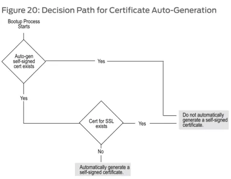
Certificate Auto-Generation . . . 58
Deleting Self-Signed Certificates . . . 60
Chapter 3 Virtual Private Network Guidelines . . . 61
Cryptographic Options . . . 61
Site-to-Site Cryptographic Options . . . 62
Dialup VPN Options . . . 69
Cryptographic Policy . . . 75
Route-Based and Policy-Based Tunnels . . . 75
Packet Flow: Site-to-Site VPN . . . 77
Addendum: Policy-Based VPN . . . 81
Tunnel Configuration Guidelines . . . 82
Route-Based Virtual Private Network Security Considerations . . . 84
Null Route . . . 84
VPN Failover to Leased Line or Null Route . . . 86
WebUI (Device A) . . . 87
CLI (Device A) . . . 88
Decoy Tunnel Interface . . . 89
Virtual Router for Tunnel Interfaces . . . 89
Reroute to Another Tunnel . . . 90
Chapter 4 Site-to-Site Virtual Private Networks . . . 91
Site-to-Site VPN Configurations . . . 91
Route-Based Site-to-Site VPN, AutoKey IKE . . . 97
WebUI (Tokyo) . . . 98
WebUI (Paris) . . . 101
CLI (Tokyo) . . . 103
CLI (Paris) . . . 104
Policy-Based Site-to-Site VPN, AutoKey IKE . . . 105
WebUI (Tokyo) . . . 106
WebUI (Paris) . . . 108
CLI (Tokyo) . . . 109
CLI (Paris) . . . 110
Route-Based Site-to-Site VPN, Dynamic Peer . . . 111
WebUI (Tokyo) . . . 112
WebUI (Paris) . . . 114
CLI (Tokyo) . . . 117
CLI (Paris) . . . 118
Policy-Based Site-to-Site VPN, Dynamic Peer . . . 119
WebUI (Device A) . . . 120
WebUI (Device B) . . . 123
CLI (Device A) . . . 125
CLI (Device B) . . . 126
Route-Based Site-to-Site VPN, Manual Key . . . 127
WebUI (Tokyo) . . . 128
WebUI (Paris) . . . 130
CLI (Tokyo) . . . 132
CLI (Paris) . . . 132
Policy-Based Site-to-Site VPN, Manual Key . . . 133
WebUI (Tokyo) . . . 134
WebUI (Paris) . . . 135
CLI (Tokyo) . . . 136
CLI (Paris) . . . 137
Dynamic IKE Gateways Using FQDN . . . 137
Aliases . . . 138
Setting AutoKey IKE Peer with FQDN . . . 139
WebUI (Tokyo) . . . 140
WebUI (Paris) . . . 143
CLI (Tokyo) . . . 145
CLI (Paris) . . . 146
VPN Sites with Overlapping Addresses . . . 147
CLI (Device A) . . . 157 CLI (Device B) . . . 157 Transparent Mode VPN . . . 158 WebUI (Device A) . . . 160 WebUI (Device B) . . . 162 CLI (Device A) . . . 164 CLI (Device B) . . . 164
Transport mode IPsec VPN . . . 165
Gateway - 1 Configuration . . . 166
GW-2 Configuration . . . 167
Chapter 5 Dialup Virtual Private Networks . . . 169
Dialup . . . 169
Policy-Based Dialup VPN, AutoKey IKE . . . 170
WebUI . . . 171
CLI . . . 173
NetScreen-Remote Security Policy Editor . . . 174
Route-Based Dialup VPN, Dynamic Peer . . . 175
WebUI . . . 176
CLI . . . 179
NetScreen-Remote . . . 180
Policy-Based Dialup VPN, Dynamic Peer . . . 182
WebUI . . . 182
CLI . . . 184
NetScreen-Remote . . . 185
Bidirectional Policies for Dialup VPN Users . . . 187
WebUI . . . 188
CLI . . . 190
NetScreen-Remote Security Policy Editor . . . 190
Group IKE ID . . . 191
Group IKE ID with Certificates . . . 192
Wildcard and Container ASN1-DN IKE ID Types . . . 193
Creating a Group IKE ID (Certificates) . . . 196
WebUI . . . 197
CLI . . . 199
NetScreen-Remote Security Policy Editor . . . 199
Setting a Group IKE ID with Preshared Keys . . . 201
WebUI . . . 202
CLI . . . 204
Obtaining the Preshared Key . . . 204
NetScreen-Remote Security Policy Editor . . . 204
Shared IKE ID . . . 206
WebUI . . . 207
CLI . . . 209
Chapter 6 Layer 2 Tunneling Protocol . . . 213
Introduction to L2TP . . . 213
Packet Encapsulation and Decapsulation . . . 215
Encapsulation . . . 216 Decapsulation . . . 216 Setting L2TP Parameters . . . 217 WebUI . . . 219 CLI . . . 219 L2TP and L2TP-over-IPsec . . . 219 Configuring L2TP . . . 220 WebUI . . . 221 CLI . . . 223 Configuring L2TP-over-IPsec . . . 224 WebUI . . . 225 CLI . . . 229
NetScreen-Remote Security Policy Editor (Adam) . . . 230
Configuring an IPsec Tunnel to Secure Management Traffic . . . 232
WebUI . . . 232
CLI . . . 233
Bidirectional L2TP-over-IPsec . . . 234
WebUI . . . 234
CLI . . . 236
NetScreen-Remote Security Policy Editor (for User “dialup-j”) . . . 237
Chapter 7 Advanced Virtual Private Network Features . . . 241
NAT-Traversal . . . 241
Probing for NAT . . . 242
Traversing a NAT Device . . . 244
UDP Checksum . . . 246 WebUI . . . 246 CLI . . . 246 Keepalive Packets . . . 246 Initiator/Responder Symmetry . . . 247 Enabling NAT-Traversal . . . 249 WebUI . . . 249 CLI . . . 249
Using IKE IDs with NAT-Traversal . . . 249
WebUI . . . 250
CLI . . . 250
VPN Monitoring . . . 251
Rekey and Optimization Options . . . 252
Source Interface and Destination Address . . . 253
Policy Considerations . . . 254
Configuring the VPN Monitoring Feature . . . 254
WebUI . . . 254
CLI . . . 255
WebUI (Device A) . . . 257
CLI (Device B) . . . 261
SNMP VPN Monitoring Objects and Traps . . . 262
Multiple Tunnels per Tunnel Interface . . . 263
Route-to-Tunnel Mapping . . . 264
Remote Peers’ Addresses . . . 265
Manual and Automatic Table Entries . . . 266
Manual Table Entries . . . 266
Automatic Table Entries . . . 267
Setting VPNs on a Tunnel Interface to Overlapping Subnets . . . 268
Binding Automatic Route and NHTB Table Entries . . . 285
Using OSPF for Automatic Route Table Entries . . . 296
Multiple Proxy IDs on a Route-Based VPN . . . 298
WebUI (Device A) . . . 299 CLI (Device A) . . . 300 WebUI (Device B) . . . 300 CLI (Device B) . . . 301 Redundant VPN Gateways . . . 302 VPN Groups . . . 302 Monitoring Mechanisms . . . 303 IKE Heartbeats . . . 303
Dead Peer Detection . . . 304
IKE Recovery Procedure . . . 306
TCP SYN-Flag Checking . . . 307 WebUI . . . 307 CLI . . . 307 WebUI (Monitor1) . . . 308 WebUI (Target1) . . . 310 WebUI (Target2) . . . 312 CLI (Monitor1) . . . 312 CLI (Target1) . . . 313 CLI (Target2) . . . 313 Creating Back-to-Back VPNs . . . 313 WebUI . . . 315 CLI . . . 318 Creating Hub-and-Spoke VPNs . . . 320
WebUI (New York) . . . 321
WebUI (Tokyo) . . . 323
WebUI (Paris) . . . 324
CLI (New York) . . . 326
CLI (Tokyo) . . . 327
CLI (Paris) . . . 327
IKE and IPsec Passthrough Traffic . . . 328
NAT-T IKE and IPsec Passthrough Traffic . . . 328
Chapter 8 AutoConnect-Virtual Private Networks . . . 331
Overview . . . 331
How It Works . . . 331
Dual-Hub AC-VPN . . . 332
NHRP Messages . . . 333
AC-VPN Tunnel Initiation . . . 334
Configuring AC-VPN . . . 335
Network Address Translation . . . 336
Configuration on the Hub . . . 336
Configuration on Each Spoke . . . 336
. . . 337 WebUI (Hub) . . . 337 CLI (Hub) . . . 340 WebUI (Spoke1) . . . 340 CLI (Spoke1) . . . 342 WebUI (Spoke2) . . . 343 CLI (Spoke2) . . . 344
Configuring Dual-Hub AC-VPN . . . 345
WebUI (Hub-m) . . . 345 CLI (Hub-m) . . . 347 WebUI (Hub-b) . . . 347 CLI (Hub-b) . . . 349 WebUI (Spoke1) . . . 350 CLI (Spoke1) . . . 352 WebUI (Spoke2) . . . 353 CLI (Spoke2) . . . 356
Part 2
Index
Index . . . 361About This Guide . . . xvii
Figure 1: Images in Illustrations . . . xx
Part 1
Virtual Private Networks
Chapter 1 Internet Protocol Security . . . 3Figure 2: IPsec Architecture . . . 5
Figure 3: Transport Modes . . . 6
Figure 4: Tunnel Modes . . . 6
Figure 5: Site-to-Site VPN in Tunnel Mode . . . 7
Figure 6: Dialup VPN in Tunnel Mode . . . 7
Figure 7: IKE Packet for Phases 1 and 2 . . . 16
Figure 8: Generic ISAKMP Payload Header . . . 17
Figure 9: ISAKMP Header with Generic ISAKMP Payloads . . . 18
Figure 10: IPsec Packet—Encapsulating Security Payload in Tunnel Mode . . . 18
Figure 11: Outer IP Header (IP2) and ESP Header . . . 19
Figure 12: Inner IP Header (IP1) and TCP Header . . . 20
Figure 13: IKEv2 Gateway Connecting Two Security Devices . . . 27
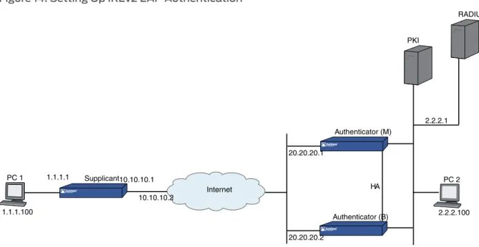
Figure 14: Setting Up IKEv2 EAP Authentication . . . 32
Chapter 2 Public Key Cryptography . . . 35
Figure 15: Digital Signature Verification . . . 36
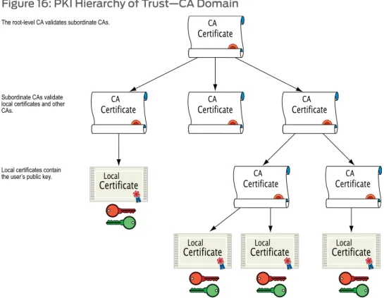
Figure 16: PKI Hierarchy of Trust—CA Domain . . . 38
Figure 17: Cross-Certification . . . 38
Figure 18: Security Alerts for Self-Signed Certificates . . . 53
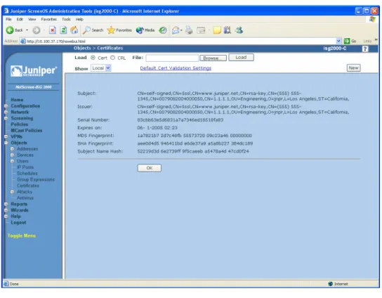
Figure 19: Certificate Details . . . 56
Figure 20: Decision Path for Certificate Auto-Generation . . . 59
Chapter 3 Virtual Private Network Guidelines . . . 61
Figure 21: Cryptographic Options for a Site-to-Site VPN Tunnel . . . 62
Figure 22: Cryptographic Options for a Dialup VPN Tunnel . . . 69
Figure 23: Site-to-Site VPN Tunnel . . . 77
Figure 24: Routing Failover Alternatives for VPN Traffic . . . 86
Figure 25: Routing Failover to a Leased Line and Then to a Null Route . . . 87
Chapter 4 Site-to-Site Virtual Private Networks . . . 91
Figure 26: Site-to-Site VPN Tunnel Configuration . . . 92
Figure 27: Site-to-Site Tunnel Configuration—Interfaces . . . 93
Figure 28: Site-to-Site Tunnel Configuration—Addresses . . . 94
Figure 32: Route-Based Site-to-Site VPN, AutoKey IKE . . . 98
Figure 33: Policy-Based Site-to-Site VPN, AutoKey IKE . . . 105
Figure 34: Route-Based Site-to-Site VPN, Dynamic Peer . . . 111
Figure 35: Policy-Based Site-to-Site VPN, Dynamic Peer . . . 119
Figure 36: Route-Based Site-to-Site VPN, Manual Key . . . 127
Figure 37: Policy-Based Site-to-Site VPN, Manual Key . . . 133
Figure 38: IKE Peer with a Dynamic IP Address . . . 138
Figure 39: Multiple DNS Replies Leading to IKE Negotiation Success or Failure . . . 139
Figure 40: AutoKey IKE Peer with FQDN . . . 140
Figure 41: Overlapping Addresses at Peer Sites . . . 149
Figure 42: Tunnel Interface with NAT-Src and NAT-Dst . . . 151
Figure 43: Transport Mode IPsec VPN . . . 165
Chapter 5 Dialup Virtual Private Networks . . . 169
Figure 44: Policy-Based Dialup VPN, AutoKey IKE . . . 171
Figure 45: Route-Based Dialup VPN, Dynamic Peer . . . 176
Figure 46: Policy-Based Dialup VPN, Dynamic Peer . . . 182
Figure 47: Group IKE ID with Certificates . . . 192
Figure 48: ASN1 Distinguished Name . . . 194
Figure 49: Successful Wildcard ASN1-DN Authentication . . . 195
Figure 50: Authentication Success and Failure Using Container ASN1-DN IDs . . 196
Figure 51: Group IKE ID . . . 197
Figure 52: Group IKE ID with Preshared Keys . . . 201
Figure 53: Group IKE ID (Preshared Keys) . . . 202
Figure 54: Shared IKE ID (Preshared Keys) . . . 207
Chapter 6 Layer 2 Tunneling Protocol . . . 213
Figure 55: L2TP Tunnel Between VPN Client (LAC) and Security Device (LNS) . . . 213
Figure 56: IP and DNS Assignments from ISP . . . 214
Figure 57: IP and DNS Assignments from LNS . . . 214
Figure 58: L2TP Packet Encapsulation . . . 216
Figure 59: L2TP Packet Decapsulation . . . 217
Figure 60: IP Pool and L2TP Default Settings . . . 219
Figure 61: Configuring L2TP . . . 221
Figure 62: Configuring L2TP-over-IPsec . . . 225
Figure 63: Configuring IPsec Tunnel for Management Traffic . . . 232
Figure 64: Bidirectional L2TP-over-IPsec . . . 234
Chapter 7 Advanced Virtual Private Network Features . . . 241
Figure 65: NAT-Traversal . . . 244
Figure 66: IKE Packet (for Phases 1 and 2) . . . 245
Figure 67: IPsec ESP Packet Before and After NAT Detection . . . 246
Figure 68: Security Device with a Dynamically Assigned IP Address Behind a NAT Device . . . 247
Figure 69: Security Device with a Mapped IP Address Behind a NAT Device . . . 248
Figure 70: Enabling NAT-Traversal . . . 249
Figure 71: Source and Destination Addresses for VPN Monitoring . . . 253
Figure 73: Route Table and Next-Hop Tunnel Binding (NHTB) Table . . . 264
Figure 74: Multiple Tunnels Bound to a Single Tunnel Interface with Address Translation . . . 266
Figure 75: Tunnel.1 interface Bound to Three VPN Tunnels . . . 268
Figure 76: Peer1 Performing NAT-Dst . . . 274
Figure 77: Peer2 . . . 278
Figure 78: Peer3 . . . 282
Figure 79: Automatic Route and NHTB Table Entries (Device A) . . . 286
Figure 80: Peer1 . . . 291
Figure 81: Peer2 . . . 294
Figure 82: Redundant VPN Gateways for VPN Tunnel Failover . . . 302
Figure 83: Targeted Remote Gateways . . . 303
Figure 84: IKE Heartbeats Flow in Both Directions . . . 304
Figure 85: Repeated IKE Phase 1 Negotiation Attempts . . . 306
Figure 86: Failover and Then Recovery . . . 307
Figure 87: Redundant VPN Gateways . . . 308
Figure 88: Back-to-Back VPNs . . . 314
Figure 89: Back-to-Back VPNs with Two Routing Domains and Multiple Security Zones . . . 315
Figure 90: Multiple Tunnels in a Hub-and-Spoke VPN Configuration . . . 320
Figure 91: Hub-and-Spoke VPNs . . . 321
Chapter 8 AutoConnect-Virtual Private Networks . . . 331
Figure 92: Dual-Hub AC-VPN . . . 333
Figure 93: AC-VPN Set Up Via NHRP . . . 335
Virtual Private Networksdescribes virtual private network (VPN) concepts and ScreenOS VPN-specific features.
This guide contains the following chapters:
• “Internet Protocol Security” on page 3provides background information about IPsec, presents a flow sequence for Phase 1 in IKE negotiations in aggressive and main modes, and concludes with information about IKE and IPsec packet encapsulation.
• “Public Key Cryptography” on page 35provides an introduction to public key
cryptography, certificate use, and certificate revocation list (CRL) use within the context of Public Key Infrastructure (PKI).
• “Virtual Private Network Guidelines” on page 61offers some useful information to help in the selection of the available VPN options. It also presents a packet flow chart to demystify VPN packet processing.
• “Site-to-Site Virtual Private Networks” on page 91provides extensive examples of VPN configurations connecting two private networks.
• “Dialup Virtual Private Networks” on page 169provides extensive examples of client-to-LAN communication using AutoKey IKE. It also details Group IKE ID and Shared IKE ID configurations.
• “Layer 2 Tunneling Protocol” on page 213explains Layer 2 Tunneling Protocol (L2TP) and provides configuration examples for L2TP and L2TP-over-IPsec.
• “Advanced Virtual Private Network Features” on page 241contains information and examples for the more advanced VPN configurations, such as NAT-Traversal, VPN monitoring, binding multiple tunnels to a single tunnel interface, and hub-and-spoke and back-to-back tunnel designs.
• “AutoConnect-Virtual Private Networks” on page 331describes how ScreenOS uses Next Hop Resolution Protocol (NHRP) messages to enable security devices to set up AutoConnect VPNs as needed. The chapter provides an example of a typical scenario in which AC-VPN might be used.
• Document Conventions on page xviii • Document Feedback on page xx
Document Conventions
This document uses the conventions described in the following sections:
• Web User Interface Conventions on page xviii • Command Line Interface Conventions on page xviii • Naming Conventions and Character Types on page xix • Illustration Conventions on page xix
Web User Interface Conventions
The Web user interface (WebUI) contains a navigational path and configuration settings. To enter configuration settings, begin by clicking a menu item in the navigation tree on the left side of the screen. As you proceed, your navigation path appears at the top of the screen, with each page separated by angle brackets.
The following example shows the WebUI path and parameters for defining an address: Policy > Policy Elements > Addresses > List > New: Enter the following, then clickOK:
Address Name: addr_1 IP Address/Domain Name:
IP/Netmask: (select), 10.2.2.5/32 Zone: Untrust
To open Online Help for configuration settings, click the question mark (?) in the upper right of the screen.
The navigation tree also provides a Help > Config Guide configuration page to help you configure security policies and Internet Protocol Security (IPSec). Select an option from the list, and follow the instructions on the page. Click the?character in the upper right for Online Help on the Config Guide.
Command Line Interface Conventions
The following conventions are used to present the syntax of command line interface (CLI) commands in text and examples.
In text, commands are inboldfacetype and variables are initalictype.
In examples:
• Variables are initalictype.
• Anything inside square brackets [ ] is optional.
• Anything inside braces { } is required.
• If there is more than one choice, each choice is separated by a pipe ( | ). For example, the following command means “set the management options for the ethernet1, the ethernet2,orthe ethernet3 interface”:
NOTE: When entering a keyword, you only have to type enough letters to identify the word uniquely. Typingset adm u whee j12fmt54will enter the commandset admin user wheezer j12fmt54. However, all the commands documented in this guide are presented in their entirety.
Naming Conventions and Character Types
ScreenOS employs the following conventions regarding the names of objects—such as addresses, admin users, auth servers, IKE gateways, virtual systems, VPN tunnels, and zones—defined in ScreenOS configurations:
• If a name string includes one or more spaces, the entire string must be enclosed within double quotes; for example:
set address trust “local LAN” 10.1.1.0/24
• Any leading spaces or trailing text within a set of double quotes are trimmed; for example,“local LAN ” becomes“local LAN”.
• Multiple consecutive spaces are treated as a single space.
• Name strings are case-sensitive, although many CLI keywords are case-insensitive. For example,“local LAN”is different from“local lan”.
ScreenOS supports the following character types:
• Single-byte character sets (SBCS) and multiple-byte character sets (MBCS). Examples of SBCS are ASCII, European, and Hebrew. Examples of MBCS—also referred to as double-byte character sets (DBCS)—are Chinese, Korean, and Japanese.
• ASCII characters from 32 (0x20 in hexadecimals) to 255 (0xff), except double quotes ( “), which have special significance as an indicator of the beginning or end of a name string that includes spaces.
NOTE: A console connection only supports SBCS. The WebUI supports both SBCS and MBCS, depending on the character sets that your browser supports.
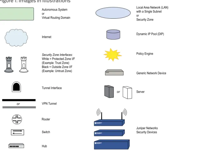
Illustration Conventions
Figure 1 on page xxshows the basic set of images used in illustrations throughout this guide.
Figure 1: Images in Illustrations
Document Feedback
If you find any errors or omissions in this document, contact Juniper Networks at [email protected].
Requesting Technical Support
Technical product support is available through the Juniper Networks Technical Assistance Center (JTAC). If you are a customer with an active J-Care or JNASC support contract, or are covered under warranty, and need postsales technical support, you can access our tools and resources online or open a case with JTAC.
• JTAC policies—For a complete understanding of our JTAC procedures and policies, review theJTAC User Guidelocated at
http://www.juniper.net/customers/support/downloads/710059.pdf.
• Product warranties—For product warranty information, visit
http://www.juniper.net/support/warranty/.
• JTAC hours of operation—The JTAC centers have resources available 24 hours a day, 7 days a week, 365 days a year.
Self-Help Online Tools and Resources
For quick and easy problem resolution, Juniper Networks has designed an online self-service portal called the Customer Support Center (CSC) that provides you with the following features:
• Find CSC offerings—http://www.juniper.net/customers/support/ • Find product documentation—http://www.juniper.net/techpubs/
• Find solutions and answer questions using our Knowledge Base—http://kb.juniper.net/ • Download the latest versions of software and review your release
notes—http://www.juniper.net/customers/csc/software/ • Search technical bulletins for relevant hardware and software
notifications—http://www.juniper.net/alerts/
• Join and participate in the Juniper Networks Community Forum—
http://www.juniper.net/company/communities/ • Open a case online in the CSC Case Manager—
http://www.juniper.net/customers/cm/
• To verify service entitlement by product serial number, use our Serial Number Entitlement (SNE) Tool—
https://tools.juniper.net/SerialNumberEntitlementSearch/
Opening a Case with JTAC
You can open a case with JTAC on the Web or by telephone.
• Use the Case Manager tool in the CSC athttp://www.juniper.net/customers/cm/.
• Call 1-888-314-JTAC (1-888-314-5822—toll free in USA, Canada, and Mexico).
For international or direct-dial options in countries without toll-free numbers, visit us at
• Internet Protocol Security on page 3 • Public Key Cryptography on page 35
• Virtual Private Network Guidelines on page 61 • Site-to-Site Virtual Private Networks on page 91 • Dialup Virtual Private Networks on page 169 • Layer 2 Tunneling Protocol on page 213
• Advanced Virtual Private Network Features on page 241 • AutoConnect-Virtual Private Networks on page 331
This chapter introduces elements of Internet Protocol security (IPsec) and describes how they relate to virtual private network (VPN) tunneling. This chapter contains the following sections:
• Introduction to Virtual Private Networks on page 3 • IPsec Concepts on page 4
• Tunnel Negotiation on page 11 • IKE and IPsec Packets on page 15
Introduction to Virtual Private Networks
A virtual private network (VPN) provides a means for securely communicating between remote computers across a public wide area network (WAN), such as the Internet. A VPN connection can link two local area networks (LANs) or a remote dialup user and a LAN. The traffic that flows between these two points passes through shared resources such as routers, switches, and other network equipment that make up the public WAN. To secure VPN communication while passing through the WAN, the two participants create an IP security (IPsec) tunnel.
NOTE: The term tunnel does not denote either transport or tunnel mode (see “Modes” on page 5). It refers to the IPsec connection.
An IPsec tunnel consists of a pair of unidirectional Security Associations (SAs)—one at each end of the tunnel—that specify the security parameter index (SPI), destination IP address, and security protocol (Authentication Header or Encapsulating Security Payload) employed.
For more information about SPIs, see“Security Associations” on page 10. For more information about IPsec security protocols, see“Protocols” on page 7.
Through the SA, an IPsec tunnel can provide the following security functions:
• Sender authentication and—if using certificates—nonrepudiation (through data origin authentication)
The security functions you employ depend on your needs. If you only need to authenticate the IP packet source and content integrity, you can authenticate the packet without applying any encryption. On the other hand, if you are only concerned with preserving privacy, you can encrypt the packet without applying any authentication mechanisms. Optionally, you can both encrypt and authenticate the packet. Most network security designers choose to encrypt, authenticate, and replay-protect their VPN traffic. ScreenOS supports IPsec technology for creating VPN tunnels with two kinds of key creation mechanisms:
• Manual Key
• AutoKey IKE with a preshared key or a certificate
IPsec Concepts
Internet Protocol security (IPsec) is a suite of related protocols for cryptographically securing communications at the IP Packet Layer. IPsec consists of two modes and two main protocols:
• Transport and tunnel modes
• The Authentication Header (AH) protocol for authentication and the Encapsulating Security Payload (ESP) protocol for encryption (and authentication)
IPsec also provides methods for the manual and automatic negotiation of security associations (SAs) and key distribution, all the attributes of which are gathered in a Domain of Interpretation (DOI). Refer to RFC 2407 and RFC 2408.
Figure 2: IPsec Architecture
NOTE: The IPsec Domain of Interpretation (DOI) is a document containing definitions for all the security parameters required for the successful negotiation of a VPN tunnel—essentially, all the attributes required for SA and IKE negotiations.
Modes
IPsec operates in one of two modes—transport or tunnel. When both ends of the tunnel are hosts, you can use either mode. When at least one of the endpoints of a tunnel is a security gateway, such as a router or firewall, you must use tunnel mode. Juniper Networks security devices always operate in tunnel mode for IPsec tunnels and transport mode for L2TP-over-IPsec tunnels.
Transport Mode
In transport mode, the original IP packet is not encapsulated within another IP packet, as shown inFigure 3 on page 6. The entire packet can be authenticated (with AH), the payload can be encrypted (with ESP), and the original header remains in plaintext as it is sent across the WAN.
Figure 3: Transport Modes
NOTE: In the current release, ScreenOS supports transport mode with AH on the high-end systems (ISG and NS series of products) for IPv4 packets only. This feature does not work if IPv6 is enabled on the device.
Tunnel Mode
In tunnel mode, the entire original IP packet—payload and header—is encapsulated within another IP payload and a new header is prepended to it, as shown inFigure 4 on page 6. The entire original packet can be encrypted, authenticated, or both. With AH, the AH and new headers are also authenticated. With ESP, the ESP header can also be authenticated.
Figure 4: Tunnel Modes
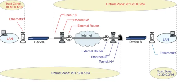
In a site-to-site VPN, the source and destination addresses used in the new header are the IP addresses of the outgoing interface (in NAT or route mode) or the VLAN1 IP address (in transparent mode); the source and destination addresses of the encapsulated packets are the addresses of the ultimate endpoints of the connection.
Figure 5: Site-to-Site VPN in Tunnel Mode
LAN 2 Internet LAN 1 B Tunnel Device-B Tunnel Gateway A Device-A Tunnel GatewayThe original packet is encapsulated.
A B Payload 1 2 A B Payload A B Payload
In a dialup VPN, there is no tunnel gateway on the VPN dialup client end of the tunnel; the tunnel extends directly to the client itself. In this case, on packets sent from the dialup client, both the new header and the encapsulated original header have the same IP address: that of the client’s computer.
NOTE: Some VPN clients such as the NetScreen-Remote allow you to define a virtual inner IP address. In such cases, the virtual inner IP address is the source IP address in the original packet header of traffic originating from the client, and the IP address that the ISP dynamically assigns the dialup client is the source IP address in the outer header.
Figure 6: Dialup VPN in Tunnel Mode
2 Internet
LAN
A B Payload 1 2 A B Payload A B Payload
A = 1 B Tunnel Device-B Tunnel Gateway VPN Dialup Client
The original packet is encapsulated.
Protocols
IPsec uses two protocols to secure communications at the IP Layer:
• Authentication Header (AH)—A security protocol for authenticating the source of an IP packet and verifying the integrity of its content
• Encapsulating Security Payload (ESP)—A security protocol for encrypting the entire IP packet (and authenticating its content)
Authentication Header
calculated through a Hash Message Authentication Code (HMAC) using a secret key and the MD5, SHA-1 or SHA-2 hash functions.
• Message Digest version 5 (MD5)—Algorithm that produces a 128-bit hash (also called adigital signatureormessage digest) from a message of arbitrary length and a 16-byte key. The resulting hash is used, like a fingerprint of the input, to verify content and source authenticity and integrity.
• Secure Hash Algorithm-1 (SHA-1)—Algorithm that produces a 160-bit hash from a message of arbitrary length and a 20-byte key. It is generally regarded as more secure than MD5 because of the larger hashes it produces. Because the computational processing is done in the ASIC, the performance cost is negligible.
• Secure Hash Algorithm-2 (SHA-2)—Set of four algorithms named after their message digest length (in bits)—SHA2-224, SHA2-256, SHA2-384, and SHA2-512. These algorithms are generally regarded as more secure than SHA-1 because of the larger hashes they produce. This release of ScreenOS supports the SHA2-256 hash algorithm. The SHA2-256 algorithm produces a 256-bit hash from a message of arbitrary length and a 32-byte key.
NOTE: For more information about the MD5, SHA-1, and SHA2-256 hashing algorithms, refer to the following RFCs: (MD5) 1321, 2403; (SHA-1) 2404; (SHA2-256) 4753, 4868. For information about HMAC, refer to RFC 2104. In the current release, ScreenOS supports transport mode with AH on the high-end systems for IPv4 packets only. This feature does not work if IPv6 is enabled on the device.
Encapsulating Security Payload
The Encapsulating Security Payload (ESP) protocol provides a means for ensuring privacy (encryption) and source authentication and content integrity (authentication). ESP in tunnel mode encapsulates the entire IP packet (header and payload) and then appends a new IP header to the now-encrypted packet. This new IP header contains the destination address needed to route the protected data through the network.
With ESP, you can both encrypt and authenticate, encrypt only, or authenticate only. For encryption, you can choose one of the following encryption algorithms:
• Data Encryption Standard (DES)—A cryptographic block algorithm with a 56-bit key.
• Triple DES (3DES)—A more powerful version of DES in which the original DES algorithm is applied in three rounds, using a 168-bit key. DES provides a significant performance savings but is considered unacceptable for many classified or sensitive material transfers.
• Advanced Encryption Standard (AES)—An emerging encryption standard which, when adopted by Internet infrastructures worldwide, will offer greater interoperability with other network security devices. ScreenOS supports AES with 128-bit, 192-bit, and 256-bit keys.
For authentication, you can use the MD5, SHA-1 or SHA2-256 algorithms.
NOTE: Even though it is possible to selectNULLfor authentication, it has been demonstrated that IPsec might be vulnerable to attack under such circumstances. Therefore, it is inadvisable to selectNULLfor authentication.
Key Management
Key distribution and management are critical to using VPNs successfully. IPsec supports both manual and automatic key-distribution methods.
Manual Key
With manual key encryption, administrators at both ends of a tunnel configure all the security parameters. This is a viable technique for small, static networks where the distribution, maintenance, and tracking of keys are not difficult. However, safely distributing manual-key configurations across great distances poses security issues. Aside from passing a key face-to-face, you cannot be completely sure that the key has not been compromised while in transit. Also, whenever you want to change the key, you are faced with the same security issues as when you initially distributed it.
AutoKey IKE
When you need to create and manage numerous tunnels, you need a method that does not require you to manually configure every element. IPsec supports the automated generation and negotiation of keys and security associations using the Internet Key Exchange (IKE) protocol. ScreenOS refers to such automated tunnel negotiation as AutoKey IKEand supports AutoKey IKE with preshared keys and AutoKey IKE with certificates.
AutoKey IKE with Preshared Keys
With AutoKey IKE which uses preshared keys to authenticate the participants in an IKE session, each side must configure and securely exchange the preshared key in advance. In this regard, the issue of secure key distribution is the same as that with manual keys. However, once distributed, an autokey, unlike a manual key, can automatically change its keys at predetermined intervals using the IKE protocol. Frequently changing keys greatly improves security, and automatically doing so greatly reduces key-management responsibilities. However, changing keys increases traffic overhead; therefore, doing so too often can reduce data transmission efficiency.
NOTE: A preshared key is a key for both encryption and decryption, which both participants must possess before initiating communication.
AutoKey IKE with Certificates
When using certificates to authenticate the participants during an AutoKey IKE negotiation, each side generates a public/private key pair (see“Public Key Cryptography” on page 35
issuing certificate authority (CA) is trusted by both sides, the participants can retrieve the peer’s public key and verify the peer’s signature. There is no need to keep track of the keys and SAs; IKE does so automatically.
NOTE: For examples of both Manual Key and AutoKey IKE tunnels, see “Site-to-Site Virtual Private Networks” on page 91.
Key Protection
Juniper Networks security devices protect VPN-persistent private keys against
unauthorized access and modification. By enabling the key protection feature, the security device encrypts VPN persistent private keys, checks integrity of the key whenever the key is used, and destroys the key memory with different key patterns in the system. The following types of VPN private keys are encrypted:
• PKI private keys (DSA/RSA/ECDSA)
• IKE preshared keys and preshared key seeds
• VPN manual keys (keys generated from passwords)
All VPN manual keys and keys generated from passwords are encrypted from plaintext to encrypted text using a master key (a hard-coded key). The same master key is used to decrypt the encrypted key back to plaintext. You cannot access the master key if you are accessing the system through any management interface. The AES (128-bit) encryption algorithm is used to encrypt the keys. The security device uses the single-parity-bit Error Detection Code (EDC) algorithm to detect key errors.
Enabling Key Protection
You can enable key protection through the WebUI or the CLI. The key protection feature is disabled by default.
WebUI
Configuration > Admin > Management: SelectEnable Key Protection,then clickApply.
CLI
set key protection enable save
Security Associations
A security association (SA) is a unidirectional agreement between the VPN participants regarding the methods and parameters to use in securing a communication channel. Full bidirectional communication requires at least two SAs, one for each direction.
An SA groups together the following components for securing communications:
• Security algorithms and keys
• Key-management method (manual key or AutoKey IKE)
• SA lifetime
For outbound VPN traffic, the policy invokes the SA associated with the VPN tunnel. For inbound traffic, the security device looks up the SA by using the following triplet:
• Destination IP
• Security protocol (AH or ESP)
• Security parameter index (SPI) value
Tunnel Negotiation
For a manual key IPsec tunnel, because all of the security association (SA) parameters have been previously defined, there is no need to negotiate which SAs to use. In essence, the tunnel has already been established. When traffic matches a policy using that manual key tunnel or when a route involves the tunnel, the security device simply encrypts and authenticates the data, as you determined, and forwards it to the destination gateway. To establish an AutoKey IKE IPsec tunnel, two phases of negotiations are required:
• In Phase 1, the participants establish a secure channel in which to negotiate the IPsec SAs.
• In Phase 2, the participants negotiate the IPsec SAs for encrypting and authenticating the ensuing exchanges of user data.
NOTE: Juniper Networks security devices support the newer version of the IKE protocol known as IKEv2. For more information about IKEv2 and how security devices establish security associations (SAs) using the IKEv2 protocol, see“IKE Version 2” on page 20.
Phase 1
Phase 1 of an AutoKey IKE tunnel negotiation consists of the exchange of proposals for how to authenticate and secure the channel. The exchange can be in one of two modes: aggressive or main. Using either mode, the participants exchange proposals for acceptable security services such as:
• Encryption algorithms (DES and 3DES) and authentication algorithms (MD5, SHA-1 or SHA2-256). For more information about these algorithms, see“Protocols” on page 7.
• A Diffie-Hellman group (see“Diffie-Hellman Exchange” on page 13).
• Preshared key or RSA/DSA certificates (see“AutoKey IKE” on page 9).
A successful Phase 1 negotiation concludes when both ends of the tunnel agree to accept at least one set of the Phase 1 security parameters proposed and then process them.
allowing you to define how restrictive a range of security parameters for key negotiation you will accept.
The predefined Phase 1 proposals that ScreenOS provides are as follows:
• Standard:pre-g2-aes128-sha and pre-g2-3des-sha
• Compatible:pre-g2-3des-sha, pre-g2-3des-md5, pre-g2-des-sha, and pre-g2-des-md5
• Basic:pre-g1-des-sha and pre-g1-des-md5
You can also define custom Phase 1 proposals.
Main and Aggressive Modes
Phase 1 can take place in either main or aggressive mode. The two modes are described below.
Main mode:The initiator and recipient send three two-way exchanges (six messages total) to accomplish the following services:
• First exchange (messages 1 and 2): Propose and accept the encryption and authentication algorithms.
• Second exchange (messages 3 and 4): Execute a DH exchange, and the initiator and recipient each provide a pseudo-random number.
• Third exchange (messages 5 and 6): Send and verify their identities.
The information transmitted in the third exchange of messages is protected by the encryption algorithm established in the first two exchanges. Thus, the participants’ identities are not transmitted in the clear.
Aggressive mode:The initiator and recipient accomplish the same objectives, but only in two exchanges, with a total of three messages:
• First message: The initiator proposes the SA, initiates a DH exchange, and sends a pseudo-random number and its IKE identity.
• Second message: The recipient accepts the SA; authenticates the initiator; and sends a pseudo-random number, its IKE identity, and, if using certificates, the recipient’s certificate.
• Third message: The initiator authenticates the recipient, confirms the exchange, and, if using certificates, sends the initiator’s certificate.
Because the participants’ identities are exchanged in the clear (in the first two messages), aggressive mode does not provide identity protection.
NOTE: When a dialup VPN user negotiates an AutoKey IKE tunnel with a preshared key, aggressive mode must be used. Note also that a dialup VPN user can use an email address, a fully qualified domain name (FQDN), or an IP address as its IKE ID. A dynamic peer can use either an email address or FQDN, but not an IP address.
Diffie-Hellman Exchange
A Diffie-Hellman (DH) exchange allows the participants to produce a shared secret value. The strength of the technique is that it allows the participants to create the secret value over an unsecured medium without passing the secret value through the wire. ScreenOS supports DH groups 1, 2, 5, and 14 for Internet Key Exchange version 1 (IKEv1) and IKE version 2 (IKEv2). The size of the prime modulus used in each group’s calculation differs as follows:
• DH group 1:768 bit
• DH group 2:1024 bit
• DH group 5:1536 bit
• DH group 14:2048 bit
NOTE: The strength of DH group 1 security has depreciated, and we do not recommend its use.
The larger the modulus, the more secure the generated key is considered to be; however, the larger the modulus, the longer the key-generation process takes. Because the modulus for each DH group is a different size, the participants must agree to use the same group.
NOTE: If you configure multiple (up to four) proposals for Phase 1 negotiations, you can use different DH groups in all proposals. The same guideline applies to multiple proposals for Phase 2 negotiations.
Elliptical Curve Diffie-Hellman
An Elliptical Curve Diffie-Hellman (ECDH) exchange is a variant of the Diffie-Hellman (DH) protocol. ECDH uses elliptical curve cryptography to generate a public-private key pair. ECDH is an integral part of the Suite B cryptography standards proposed by the National Security Agency (NSA) for protecting both classified and unclassified information. Suite B cryptography complements NSA’s existing policy for using AES. In addition to AES, Suite B includes cryptographic algorithms for hashing, digital signatures, and key exchanges. Previous releases of ScreenOS already support most Suite B requirements with the exception of ECDH. In the current release, ScreenOS supports ECDH groups 19 and 20 for Phase 1 and Phase 2 IKEv1 negotiations only.
The advantage of ECDH over classic DH is that ECDH significantly reduces the size of the public-private key pair. The size of the prime modulus used in each group’s calculation differs as follows:
• DH group 19:256 bits ECDH prime curve
NOTE: You cannot configure ECDH groups on IKEv2 gateways. If you attempt to configure a Phase 1 or 2 proposal that uses an ECDH group, the security device generates the following error:ECDH groups are not supported by IKEv2. Use Oakley group 1, 2, 5, or 14 for IKEv2 negotiations.
Phase 2
After the participants have established a secure and authenticated channel, they proceed through Phase 2, in which they negotiate the SAs to secure the data to be transmitted through the IPsec tunnel.
Like the process for Phase 1, the participants exchange proposals to determine which security parameters to employ in the SA. A Phase 2 proposal also includes a security protocol—either Encapsulating Security Payload (ESP) or Authentication Header (AH)—and selected encryption and authentication algorithms. The proposal can also specify a DH group, if Perfect Forward Secrecy (PFS) is desired.
Regardless of the mode used in Phase 1, Phase 2 always operates in quick mode and involves the exchange of three messages.
Juniper Networks security devices support up to four proposals for Phase 2 negotiations, allowing you to define how restrictive a range of tunnel parameters you will accept. ScreenOS also provides a replay protection feature. Use of this feature does not require negotiation because packets are always sent with sequence numbers. You simply have the option of checking or not checking the sequence numbers. (For more information about replay protection, see“Replay Protection” on page 15.)
The predefined Phase 2 proposals that ScreenOS provides are as follows:
• Standard:g2-esp-3des-sha and g2-esp-aes128-sha
• Compatible:nopfs-esp-3des-sha, nopfs-esp-3des-md5, nopfs-esp-des-sha, and nopfs-esp-des-md5
• Basic:nopfs-esp-des-sha and nopfs-esp-des-md5
You can also define custom Phase 2 proposals.
In Phase 2, the peers also exchange proxy IDs. A proxy ID is a three-part tuple consisting of local IP address–remote IP address–service. The proxy ID for both peers must match, which means that the service specified in the proxy ID for both peers must be the same, and the local IP address specified for one peer must be the same as the remote IP address specified for the other peer.
NOTE:Phase 2 negotiations for IPv6 support Netscreen Redundancy Protocol (NSRP).
The CREATE_CHILD_SA exchange in an IKEv2 exchange corresponds to the Phase 2 negotiations in IKEv1. For more information, see“Initial Exchanges” on page 20.
Perfect Forward Secrecy
Perfect Forward Secrecy (PFS) is a method for deriving Phase 2 keys independent from and unrelated to the preceding keys. Alternatively, the Phase 1 proposal creates the key (the SKEYID_d key) from which all Phase 2 keys are derived. The SKEYID_d key can generate Phase 2 keys with a minimum of CPU processing. Unfortunately, if an unauthorized party gains access to the SKEYID_d key, all your encryption keys are compromised.
PFS addresses this security risk by forcing a new Diffie-Hellman key exchange to occur for each Phase 2 tunnel. Using PFS is thus more secure, although the rekeying procedure in Phase 2 might take slightly longer with PFS enabled.
Replay Protection
A replay attack occurs when somebody intercepts a series of packets and uses them later either to flood the system, causing a denial of service (DoS), or to gain entry to the trusted network. The replay-protection feature enables security devices to check every IPsec packet to see if it has been received previously. If packets arrive outside a specified sequence range, the security device rejects them.
IKE and IPsec Packets
An IPsec VPN tunnel consists of two major elements:
• Tunnel Setup:The peers first establish security associations (SAs), which define the parameters for securing traffic between themselves. The admins at each end can define the SAs manually, or the SAs can be defined dynamically through IKE Phase 1 and Phase 2 negotiations. Phase 1 can occur in either main or aggressive mode. Phase 2 always occurs in quick mode.
• Applied Security:IPsec protects traffic sent between the two tunnel endpoints by using the security parameters defined in the SAs that the peers agreed to during the tunnel setup. IPsec can be applied in one of two modes—transport or tunnel. Both modes support the two IPsec protocols—Encapsulating Security Payload (ESP) and Authentication Header (AH).
For an explanation of the packet processing that occurs during the IKE and IPsec stages of a VPN tunnel, see“IKE Packets” on page 15and“IPsec Packets” on page 18. These sections show the packet headers for IKE and IPsec, respectively.
IKE Packets
When a clear-text packet arrives at the security device that requires tunneling and no active Phase 2 SA exists for that tunnel, the security device begins IKE negotiations (and drops the packet). The source and destination addresses in the IP packet header are those of the local and remote IKE gateways, respectively. In the IP packet payload, there is a UDP segment encapsulating an Internet Security Association and Key Management
Protocol (ISAKMP), or IKE, packet. The format for IKE packets is the same for Phase 1 and Phase 2.
NOTE: When the initial IP packet is dropped, the source host resends it. Typically, by the time the second packet reaches the security device, IKE negotiations are complete and the security device protects it—and all subsequent packets in the session—with IPsec before forwarding it.
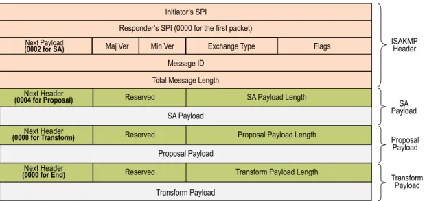
Figure 7: IKE Packet for Phases 1 and 2
The Next Payload field contains a number indicating one of the following payload types:
• 0002—SA Negotiation Payload: contains a definition for a Phase 1 or Phase 2 SA.
• 0004—Proposal Payload: can be a Phase 1 or Phase 2 proposal.
• 0008—Transform Payload: the transform payload gets encapsulated in a proposal payload which gets encapsulated in an SA payload.
• 0010—Key Exchange (KE) Payload: contains information necessary to perform a key exchange, such as a Diffie-Hellman public value.
• 0020—Identification (IDx) Payload.
• In Phase 1, IDii indicates the initiator ID, and IDir indicates the responder ID.
• In Phase 2, IDui indicates the user initiator, and IDur indicates the user responder. The IDs are IKE ID types such as FQDN, U-FQDN, IP address, and ASN.1_DN.
• 0040—Certificate (CERT) Payload.
• 0080—Certificate Request (CERT_REQ) Payload.
• 0100—Hash (HASH) Payload: contains the digest output of a particular hash function.
• 0200—Signature (SIG) Payload: contains a digital signature.
• 0400—Nonce (Nx) Payload: contains some pseudo-random information necessary for the exchange).
• 0800—Notify Payload.
• 1000—ISAKMP Delete Payload.
• 2000—Vendor ID (VID) Payload: can be included anywhere in Phase 1 negotiations. ScreenOS uses it to mark support for Network Address Translation-Traversal (NAT-T). Each ISAKMP payload begins with the same generic header, as shown inFigure 8 on page 17.
Figure 8: Generic ISAKMP Payload Header
There can be multiple ISAKMP payloads chained together, with each subsequent payload type indicated by the value in the Next Header field. A value of0000indicates the last ISAKMP payload. SeeFigure 9 on page 18for an example.
Figure 9: ISAKMP Header with Generic ISAKMP Payloads
IPsec Packets
After IKE negotiations complete and the two IKE gateways have established Phase 1 and Phase 2 security associations (SAs), the security device applies IPsec protection to subsequent clear-text IP packets that hosts behind one IKE gateway send to hosts behind the other gateway (assuming that policies permit the traffic). If the Phase 2 SA specifies the Encapsulating Security Protocol (ESP) in tunnel mode, the packet looks like the one shown below. The security device adds two additional headers to the original packet that the initiating host sends.
NOTE: For information about ESP, see“Encapsulating Security Payload” on page 8. For information about tunnel mode, see“Tunnel Mode” on page 6.
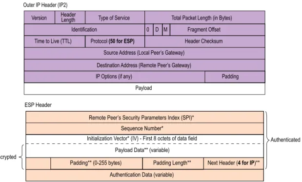
Figure 10: IPsec Packet—Encapsulating Security Payload in Tunnel Mode
As shown inFigure 10 on page 18, the packet that the initiating host constructs includes the payload, the TCP header, and the inner IP header (IP1).
The outer IP header (IP2), which the security device adds, contains the IP address of the remote gateway as the destination IP address and the IP address of the local security device as the source IP address. The security device also adds an ESP header between the outer and inner IP headers. The ESP header contains information that allows the remote peer to properly process the packet when it receives it. This is illustrated inFigure 11 on page 19.
Figure 11: Outer IP Header (IP2) and ESP Header
The Next Header field indicates the type of data in the payload field. In tunnel mode, this value is 4, indicating IP-in-IP. If ESP is applied in transport mode, this value indicates a Transport Layer protocol such as 6 for TCP or 17 for UDP.
Figure 12: Inner IP Header (IP1) and TCP Header
IKE Version 2
Juniper Networks security devices support a newer version of the Internet Key Exchange protocol (IKE), known as IKE version 2 (IKEv2). IKEv2 brings together various aspects of exchanging keys between IPsec endpoints, such as NAT-T, extended authentication (xauth), and ISAKMP configuration, into a single protocol and preserves most of the features of the earlier version, including identity hiding, PFS, two phases of establishing SAs, and cryptographic negotiation.
IKEv2 performs mutual authentication between two IPsec endpoints and establishes an IKE SA known asIKE_SA,in which the IPsec endpoints share secret information to establish SAs for Encapsulating Security Payload (ESP) protocol, Authentication Header (AH), and a set of cryptographic algorithms to be used to protect IKE traffic. The SAs for ESP or AH that get set up through the IKE_SA are calledCHILD_SAs.
IKEv2 supports three types of exchanges: initial, CREATE_CHILD_SA, and informational. Conceptually, IKEv2 IKE_SA and CHILD_SA are equivalent to IKEv1 Phase 1 SA and Phase 2 SA, respectively.
Initial Exchanges
The IPsec endpoints start an IKEv2 SA through an initial exchange. This consists of two exchanges: IKE_SA_INIT and IKE_AUTH.
IKE_SA_INIT Exchange
An IKE_SA_INIT exchange negotiates security suites, establishes the IKE_SA, and generates the SKEYSEED from which all keys are derived for the IKE_SA. Separate keys are computed for each direction. The initiator sends the following:
• HDR—Initiator’s IKE header. The header contains the security parameter indexes (SPIs), version, and flags.
• SAi1—Cryptographic algorithms the initiator supports for the IKE_SA.
• KEi—Initiator’s Diffie-Hellman value
• Ni—Initiator’s nonce
The responder sends the response to the initiator request with the following:
• HDR—Responder’s header
• SAr1—Cryptographic algorithms the responder supports for the IKE_SA.
• KEr—Responder’s Diffie-Hellman value
• Nr—Responder’s nonce
• [CERTREQ]—[Optional] Certificate request
IKE_AUTH Exchange
The IKE_AUTH exchange authenticates IKE endpoints and establishes the CHILD_SA. This exchange consists of a single request/response pair. The initiator starts using the new CHILD_SA immediately after receiving the responder's response; similarly, the responder starts using the new CHILD_SA immediately after sending the response to the initiator.
In the endpoint-to-security gateway scenario where the endpoint is an Internet remote access client (IRAC) and the security gateway is an Internet remote access server (IRAS), the IRAC needs an IP address associated with the security gateway to establish a connection with the protected subnet through an IPSec tunnel. In support of this, IKEv2 enables the IRAC to request an IP address owned by the IRAS for use in the secure connection. The IRAC requests an IP address by sending a configuration payload (CP) request in the IKE_AUTH exchange. The IRAS selects an IP address from the address pool it maintains or from the external RADIUS server and sends it to the IRAC. The assigned IP address is freed when its associated IKE_SA lifetime ends. CP also supports to assign DNS and WINS servers addresses. The IRAC gets the DNS and WINS servers addresses from the IRAS itself or from an external RADIUS server.
NOTE: IKEv2 CP is not supported for IPv6 addresses.
All messages following the initial exchange are cryptographically protected using the cryptographic algorithms and keys negotiated in the first two messages of the key exchange. These subsequent messages use the syntax of the encrypted payload. During
• HDR—Initiator’s header
• IDi—Initiator’s ID
• [CERT]—[Optional] Certificate
• [CERTREQ]—[Optional] Certificate Request
• IDr—Responder’s ID
• AUTH—Authenticates the previous message and the initiator’s identity
• CP (CFG_REQUEST)—[Optional] Exchanges the configuration information between the IKE peers
• SAi2—Initiator’s SA
• TSi—Initiator’s traffic selector
• TSr—Responder’s traffic selector
The responder sends the following response:
• HDR—Responder’s header
• IDr—Initiator’s ID
• [CERT]—[Optional] Certificate
• AUTH—Authenticates the previous message and the initiator’s identity
• CP (CFG_REPLY)—[Optional] Exchanges the configuration information between the IKE peers
• SAr2—Responder's SA
• TSi—Initiator’s traffic selector
• TSr—Responder’s traffic selector
Of these messages, except the Header, all other payload are encrypted with the secret key generated by the endpoints.
Example: Configuring IRAC and IRAS to Get an IP Address from a Local and External Databases
WebUI
1. Configuring IRAS to Get an IP Address from a Local IP Pool:
VPN > AutoKey Advanced > MODECFG Profile: Enter the following, then clickNew:
Profile Name: test IP Pool: ippool_test DNS IP1: 10.0.0.1 IP2: 10.0.0.2 WINS IP1: 10.0.0.3 IP2: 10.0.0.4
VPNs > AutoKey Advanced > Gateway > EAP > MODECFG Enable: Perform the following actions, then clickOK.
Server: select
Action: select Add Route
Information Origin: select Use Local DNS Profile: test
2. Configuring IRAC to Get an IP address from a Local IP Pool:
VPNs > AutoKey Advanced > Gateway > EAP > MODECFG Enable: selectClient, then clickOK.
CLI
1. Configuring IRAS to Get an IP Address from a Local IP Pool:
set ippool ippool_test 10.0.0.5 10.0.0.10 set ike modecfg profile name test
set ike modecfg profile test ippool ippool_test set ike modecfg profile test dns1 10.0.0.1 set ike modecfg profile test dns2 10.0.0.2 set ike modecfg profile test wins1 10.0.0.3 set ike modecfg profile test wins2 10.0.0.4
set ike gateway ikev2 gate_test modecfg server profile test
2. Configuring IRAC to Get an IP Address from a Local IP Pool:
set ike gateway ikev2 gate_test modecfg client WebUI
1. Configuring IRAS to an Get an IP Address from an EAP and External RADIUS Server: Configuation > Auth > Auth Servers > New: Enter the following, then clickOK.
Name: 202.0.0.1 Account Type: IKEv2EAP Radius: select
Radius Port: 1812 Shared Secret: 1111
VPN >AutoKey Advanced >Gateway > EAP and perform the following actions:
IKEv2 EAP Authentication: (select) Authenticator: (select)
Send ID: (select) Query Config:
Select VPN >AutoKey Advanced >Gateway >EAP > New> IKEv2 Advanced and perform the following:
IKEv2 Auth Method: (select) Self: select rsa-sig
Peer: select eap
VPNs > AutoKey Advanced > Gateway > EAP > MODECFG Enable: Perform the following actions, then clickOK.
Server:
Action: select Add Route
2. Configuring IRAC to Get an IP Address from an EAP and External RADIUS Server: Select VPN >AutoKey Advanced >Gateway >EAP and perform the following actions:
IKEv2 EAP Authentication: (select) Supplicant: (select)
User Name: temp Password: temp
Select VPN >AutoKey Advanced >Gateway >EAP > New> IKEv2 > Advanced and perform the following:
IKEv2 Auth Method: (select) Self: rsa-sig
Peer:eap
VPNs > AutoKey Advanced > Gateway > EAP > MODECFG Enable: SelectClient, then clickOK.
CLI
1. Configuring IRAS to Get an IP Address from an EAP and External RADIUS Server:
set auth-server test server-name 202.0.0.1 set auth-server test account-type eap-ikev2 set auth-server test radius port 1812 set auth-server test radius secret 1111
set ike gateway ikev2 gate_test eap authenticator passthrough test send-id-req query-config
set ike gateway ikev2 "v2-gw3" auth-method self rsa-sig peer eap set ike gateway ikev2 gate_test modecfg server
2. Configuring IRAC to Get an IP Address from an EAP and External Radius Server:
set ike gateway ikev2 gate_test eap supplicant md5 username temp password temp set ike gateway ikev2 gate_test eap supplicant md5 username temp password temp set ike gateway ikev2 gate_test modecfg client
Example: Verifying if IRAS and IRAC receives the IP address
1. To verify if IRAS receives the IP address, use theget interface tunnelinter_tunCLI for route-based VPN as given below.
ssg5-serial->get int t.1
…
tun.1 88.1.1.5/32 Untrust N/A R
-## 2008-11-12 10:43:37 : IKE<20.1.1.2> ****** Recv packet if <ethernet0/0> of vsys <Root> ******
## 2008-11-12 10:43:37 : IKE<20.1.1.2> Catcher: get 252 bytes. src port 500 ## 2008-11-12 10:43:37 : IKE<0.0.0.0 > found existing ike sa node 29319a8 ## 2008-11-12 10:43:37 : IKE<20.1.1.2 > Search IKE_SA table, found 29319a8 ## 2008-11-12 10:43:37 : Duplicated pkt checking ...
## 2008-11-12 10:43:37 : len in wind 288, hash in wind 1606591330, len 252, hash 0 ## 2008-11-12 10:43:37 : hash in SA is a1dd69b2, len 252
## 2008-11-12 10:43:37 : IKE<0.0.0.0 > payload len 12, next payload type<39><AUTH> ## 2008-11-12 10:43:37 : IKE<0.0.0.0 > payload len 28, next payload type<47><CFG> ## 2008-11-12 10:43:37 : IKE<0.0.0.0 > payload len 12, next payload type<33><SA> ## 2008-11-12 10:43:37 : IKE<0.0.0.0 > payload len 80, next payload type<41><NOTIF> ## 2008-11-12 10:43:37 : IKE<0.0.0.0 > payload len 8, next payload type<41><NOTIF>
## 2008-11-12 10:43:37 : IKE<0.0.0.0 > payload len 8, next payload type<44><TSi> ## 2008-11-12 10:43:37 : IKE<0.0.0.0 > payload len 24, next payload type<45><TSr> ## 2008-11-12 10:43:37 : IKE<0.0.0.0 > payload len 24, next payload type<0><unknown> ## 2008-11-12 10:43:37 : start seq no is 1, avil seq no is 0, win size is 1
## 2008-11-12 10:43:37 : return seq no 1 as Responder
## 2008-11-12 10:43:37 : start seq no is 2, avil seq no is 0, win size is 1
## 2008-11-12 10:43:37 : IKE<0.0.0.0 > ISAKMP msg: ver 20, len 224, nxp 35 exch 35[IKE SA AUTH], flag 08(I(1) R(0) V(0)),
...
## 2008-11-12 10:43:37 :Processing CP
## 2008-11-12 10:43:37 :Receive CP req: ip 0.0.0.0
...
## 2008-11-12 10:43:37 :Construct CP reply
## 2008-11-12 10:43:37 :Construct CP reply: ip addr 88.1.1.5
2. To verify if IRAC receives the IP address, usedebug ike detailfor policy-based VPN as given below.
debug ike detail
## 2008-11-12 11:10:27 : Enter IKEv2 init IKE_AUTH post processing, state 0 ## 2008-11-12 11:10:27 : Constructing IKE_AUTH request
## 2008-11-12 11:10:27 : construct_ike_auth, send-auth 1send_cp 1
## 2008-11-12 11:10:27 : Construct IKEv2 header.
## 2008-11-12 11:10:27 : Msg header built (next payload #0) 2008-11-12 11:10:27 : ID type 1, len 4.
## 2008-11-12 11:10:27 : initiator auth data len = 14. ## 2008-11-12 11:10:27 :Construct [CP] request: ip 0.0.0.0
## 2008-11-12 11:10:27 : Construct [SA] (CHILD_SA) request for IKEv2. conn->new_spi_r = 29504c0, &conn->new_spi_r = 29504c0.
## 2008-11-12 11:10:27 : Construct [SA] (CHILD_SA) request for IKEv2. spi = 43242975 …
## 2008-11-12 11:10:27 : IKE<20.1.1.1> ****** Recv packet if <ethernet0/0> of vsys <Root> ******
## 2008-11-12 11:10:27 : IKE<20.1.1.1> Catcher: get 220 bytes. src port 500 ## 2008-11-12 11:10:27 : IKE<0.0.0.0 > found existing ike sa node 28dbbe4 ## 2008-11-12 11:10:27 : IKE<20.1.1.1 > Search IKE_SA table, found 28dbbe4.
## 2008-11-12 11:10:27 : IKE<0.0.0.0 > payload len 12, next payload type<39><AUTH>
## 2008-11-12 11:10:27 : IKE<0.0.0.0 > payload len 28, next payload type<47><CFG>
## 2008-11-12 11:10:27 : IKE<0.0.0.0 > payload len 16, next payload type<33><SA> ## 2008-11-12 11:10:27 : IKE<0.0.0.0 > payload len 40, next payload type<41><NOTIF> ## 2008-11-12 11:10:27 : IKE<0.0.0.0 > payload len 8, next payload type<41><NOTIF> ## 2008-11-12 11:10:27 : IKE<0.0.0.0 > payload len 8, next payload type<44><TSi> ## 2008-11-12 11:10:27 : IKE<0.0.0.0 > payload len 24, next payload type<45><TSr> ## 2008-11-12 11:10:27 : IKE<0.0.0.0 > payload len 24, next payload type<0><unknown< ## 2008-11-12 11:10:27 : start seq no is 1, avil seq no is 2, win size is 1
## 2008-11-12 11:10:27 : return seq no 1 as Initiator
## 2008-11-12 11:10:27 : start seq no is 2, avil seq no is 2, win size is 1
## 2008-11-12 11:10:27 : IKE<0.0.0.0 > ISAKMP msg: ver 20, len 188, nxp 36 exch 35[IKE SA AUTH], flag 20(I(0) R(1) V(0)), msgid 1
...
## 2008-11-12 11:10:27 :Processing CP
## 2008-11-12 11:10:27 :Receive CP payload: ip 88.1.1.5.
## 2008-11-12 11:10:27 : ikmpd.c ike_if_ip_post_change_callback 6383, interface tunnel.1 pre change callabck for ike