Dual-Stack Architecture with IPv6
Release
6.3.0, Rev. 02
Published: 2012-12-10 Revision 02
Juniper Networks, Junos, Steel-Belted Radius, NetScreen, and ScreenOS are registered trademarks of Juniper Networks, Inc. in the United States and other countries. JunosE is a trademark of Juniper Networks, Inc. All other trademarks, service marks, registered trademarks, or registered service marks are the property of their respective owners.
Juniper Networks assumes no responsibility for any inaccuracies in this document. Juniper Networks reserves the right to change, modify, transfer, or otherwise revise this publication without notice.
Products made or sold by Juniper Networks or components thereof might be covered by one or more of the following patents that are owned by or licensed to Juniper Networks: U.S. Patent Nos. 5,473,599, 5,905,725, 5,909,440, 6,192,051, 6,333,650, 6,359,479, 6,406,312, 6,429,706, 6,459,579, 6,493,347, 6,538,518, 6,538,899, 6,552,918, 6,567,902, 6,578,186, and 6,590,785.
Copyright © 2009, Juniper Networks, Inc. All rights reserved.
Revision History
December 2012—Revision 02
Content subject to change. The information in this document is current as of the date listed in the revision history.
SOFTWARE LICENSE
The terms and conditions for using this software are described in the software license contained in the acknowledgment to your purchase order or, to the extent applicable, to any reseller agreement or end-user purchase agreement executed between you and Juniper Networks. By using this software, you indicate that you understand and agree to be bound by those terms and conditions.
Generally speaking, the software license restricts the manner in which you are permitted to use the software and may contain prohibitions against certain uses. The software license may state conditions under which the license is automatically terminated. You should consult the license for further details.
For complete product documentation, please see the Juniper Networks Website atwww.juniper.net/techpubs. END USER LICENSE AGREEMENT
The Juniper Networks product that is the subject of this technical documentation consists of (or is intended for use with) Juniper Networks software. Use of such software is subject to the terms and conditions of the End User License Agreement (“EULA”) posted at
http://www.juniper.net/support/eula.html. By downloading, installing or using such software, you agree to the terms and conditions of that EULA.
About This Guide . . . xvii
Part 1
Dual-Stack Architecture with IPv6
Chapter 1 Internet Protocol Version 6 Introduction . . . 3Chapter 2 IPv6 Configuration . . . 11
Chapter 3 Connection and Network Services . . . 35
Chapter 4 Static and Dynamic Routing . . . 53
Chapter 5 Address Translation . . . 81
Chapter 6 IPv6 in an IPv4 Environment . . . 95
Chapter 7 IPsec Tunneling . . . 107
Chapter 8 IPv6 XAuth User Authentication . . . 127
Part 2
Appendix
Appendix A Switching . . . 163Part 3
Index
Index . . . 167About This Guide . . . xvii
Document Conventions . . . xviii
Document Feedback . . . xx
Requesting Technical Support . . . xx
Part 1
Dual-Stack Architecture with IPv6
Chapter 1 Internet Protocol Version 6 Introduction . . . 3Overview . . . 3 IPv6 Addressing . . . 4 Notation . . . 4 Prefixes . . . 4 Address Types . . . 4 Unicast Addresses . . . 5 Anycast Addresses . . . 5 Multicast Addresses . . . 5 IPv6 Headers . . . 6 Basic Header . . . 6 Extension Headers . . . 7
IPv6 Packet Handling . . . 8
IPv6 Router and Host Modes . . . 9
IPv6 Tunneling Guidelines . . . 9
Chapter 2 IPv6 Configuration . . . 11
Overview . . . 11
Address Autoconfiguration . . . 11
Extended Unique Identifier . . . 12
Router Advertisement Messages . . . 12
Router Solicitation Messages . . . 12
Prefix Lists . . . 12
Neighbor Discovery . . . 13
Neighbor Cache Table . . . 13
Neighbor Unreachability Detection . . . 14
Neighbor Entry Categories . . . 14
Neighbor Reachability States . . . 14
How Reachability State Transitions Occur . . . 15
Enabling an IPv6 Environment . . . 18
Enabling IPv6 at the Device Level . . . 18
Configuring an IPv6 Host . . . 19
Binding the IPv6 Interface to a Zone . . . 19
WebUI . . . 19
CLI . . . 19
Enabling IPv6 Host Mode . . . 20
WebUI . . . 20
CLI . . . 20
Setting an Interface Identifier . . . 20
WebUI . . . 20
CLI . . . 20
Configuring Address Autoconfiguration . . . 20
WebUI . . . 20
CLI . . . 20
Configuring Neighbor Discovery . . . 21
WebUI . . . 21
CLI . . . 21
Configuring an IPv6 Router . . . 21
Binding the IPv6 Interface to a Zone . . . 21
WebUI . . . 22
CLI . . . 22
Enabling IPv6 Router Mode . . . 22
WebUI . . . 22
CLI . . . 22
Setting an Interface Identifier . . . 22
WebUI . . . 22
CLI . . . 22
Setting Address Autoconfiguration . . . 22
Outgoing Router Advertisements Flag . . . 23
Managed Configuration Flag . . . 23
Other Parameters Configuration Flag . . . 23
Disabling Address Autoconfiguration . . . 24
WebUI . . . 24
CLI . . . 24
Setting Advertising Time Intervals . . . 24
Advertised Reachable Time Interval . . . 24
Advertised Retransmit Time Interval . . . 25
Maximum Advertisement Interval . . . 25
Minimum Advertisement Interval . . . 25
Advertised Default Router Lifetime . . . 26
Advertising Packet Characteristics . . . 26
Link MTU Value . . . 26
Current Hop Limit . . . 26
Advertising Router Characteristics . . . 27
Link Layer Address Setting . . . 27
Advertised Router Preference . . . 27
Configuring Neighbor Discovery Parameters . . . 27
Neighbor Unreachability Detection . . . 28
MAC Session-Caching . . . 28
Base Reachable Time . . . 29
Probe Time . . . 29
Retransmission Time . . . 30
Duplicate Address Detection Retry Count . . . 30
Viewing IPv6 Interface Parameters . . . 30
WebUI . . . 30
CLI . . . 30
Viewing Neighbor Discovery Configurations . . . 30
WebUI . . . 30
CLI . . . 31
Viewing the Current RA Configuration . . . 31
WebUI . . . 31
CLI . . . 31
Multicast Listener Discovery Protocol . . . 31
WebUI . . . 32 CLI . . . 32 Configuration Examples . . . 33 IPv6 Router . . . 33 CLI . . . 33 IPv6 Host . . . 33 CLI (Device B) . . . 33
Chapter 3 Connection and Network Services . . . 35
Overview . . . 35
Dynamic Host Configuration Protocol Version 6 . . . 35
Device-Unique Identification . . . 36
Identity Association Prefix Delegation-Identification . . . 36
Prefix Features . . . 36
Server Preference . . . 37
WebUI . . . 37
CLI . . . 37
Dynamic IPv6 Prefix and DNS Information Update . . . 37
Configuring a DHCPv6 Server . . . 38 WebUI . . . 39 CLI . . . 39 Configuring a DHCPv6 Client . . . 40 WebUI . . . 40 CLI . . . 41
Configuring DHCPv6 Relay Agent . . . 41
Setting up a DHCPv6 relay agent . . . 42
Relay Agent Behavior . . . 43
Server Behavior . . . 43
Viewing DHCPv6 Settings . . . 45
Configuring Domain Name System Servers . . . 45
WebUI . . . 46
CLI . . . 46
Requesting DNS and DNS Search List Information . . . 46
WebUI (Server) . . . 46
CLI (Server) . . . 46
CLI (Client) . . . 47
Setting Proxy DNS Address Splitting . . . 47
WebUI . . . 48 CLI . . . 48 Configuring PPPoE . . . 49 WebUI . . . 50 CLI . . . 50 Setting Fragmentation . . . 50 WebUI . . . 51 CLI . . . 51
Chapter 4 Static and Dynamic Routing . . . 53
Overview . . . 53
Dual Routing Tables . . . 53
Static and Dynamic Routing . . . 54
Upstream and Downstream Prefix Delegation . . . 54
Static Routing . . . 55
WebUI . . . 55
CLI . . . 55
RIPng Configuration . . . 56
Creating and Deleting a RIPng Instance . . . 56
Creating a RIPng Instance . . . 56
Deleting a RIPng Instance . . . 57
Enabling and Disabling RIPng on an Interface . . . 57
Enabling RIPng on an Interface . . . 57
Disabling RIPng on an Interface . . . 58
Global RIPng Parameters . . . 58
Advertising the Default Route . . . 59
WebUI . . . 59
CLI . . . 59
Rejecting Default Routes . . . 59
WebUI . . . 60
CLI . . . 60
Configuring Trusted Neighbors . . . 60
WebUI . . . 60
CLI . . . 60
Redistributing Routes . . . 61
WebUI . . . 61
CLI . . . 62
Protecting Against Flooding by Setting an Update Threshold . . . 62
WebUI . . . 62
RIPng Interface Parameters . . . 62
Route, Interface, and Offset Metrics . . . 63
Access Lists and Route Maps . . . 63
Static Route Redistribution . . . 64
Configuring Split Horizon with Poison Reverse . . . 66
WebUI . . . 66
CLI . . . 66
Viewing Routing and RIPng Information . . . 66
Viewing the Routing Table . . . 66
WebUI . . . 66
CLI . . . 67
Viewing the RIPng Database . . . 67
WebUI . . . 67
CLI . . . 67
Viewing RIPng Details by Virtual Router . . . 68
WebUI . . . 68
CLI . . . 68
Viewing RIPng Details by Interface . . . 68
WebUI . . . 69
CLI . . . 69
Viewing RIPng Neighbor Information . . . 69
WebUI . . . 69
CLI . . . 69
Configuration Examples . . . 70
Enabling RIPng on Tunnel Interfaces . . . 70
WebUI (Device A) . . . 70
CLI (Device A) . . . 71
Avoiding Traffic Loops to an ISP Router . . . 71
Configuring the Customer Premises Equipment . . . 72
Configuring the Gateway . . . 75
Configuring the ISP Router . . . 78
Setting a Null Interface Redistribution to OSPF . . . 79
WebUI (OSPF for Gateway Router) . . . 79
CLI (Gateway) . . . 79
WebUI (ISP) . . . 79
CLI (ISP) . . . 79
Redistributing Discovered Routes to OSPF . . . 80
WebUI (Gateway) . . . 80
CLI (Gateway) . . . 80
Setting Up OSPF-Summary Import . . . 80
WebUI (Gateway) . . . 80
Chapter 5 Address Translation . . . 81
Overview . . . 81
Translating Source IP Addresses . . . 82
DIP from IPv6 to IPv4 . . . 82
DIP from IPv4 to IPv6 . . . 83
Translating Destination IP Addresses . . . 83
MIP from IPv6 to IPv4 . . . 83
MIP from IPv4 to IPv6 . . . 84
Configuration Examples . . . 84
IPv6 Hosts to Multiple IPv4 Hosts . . . 84
WebUI . . . 86
CLI . . . 86
IPv6 Hosts to a Single IPv4 Host . . . 86
WebUI . . . 87
CLI . . . 88
IPv4 Hosts to Multiple IPv6 Hosts . . . 88
WebUI . . . 89
CLI . . . 89
IPv4 Hosts to a Single IPv6 Host . . . 90
WebUI . . . 90
CLI . . . 91
Translating Addresses for Domain Name System Servers . . . 91
WebUI . . . 92
CLI . . . 92
WebUI . . . 93
CLI . . . 93
Chapter 6 IPv6 in an IPv4 Environment . . . 95
Overview . . . 95
Configuring Manual Tunneling . . . 96
WebUI (Device A) . . . 96
WebUI (Device B) . . . 97
CLI (Device A) . . . 97
CLI (Device B) . . . 98
Configuring 6to4 Tunneling . . . 99
6to4 Routers . . . 99
6to4 Relay Routers . . . 100
Tunnels to Remote Native Hosts . . . 100
WebUI (Device A) . . . 101
WebUI (Device B) . . . 101
CLI (Device A) . . . 102
CLI (Device B) . . . 103
Tunnels to Remote 6to4 Hosts . . . 103
WebUI (Device A) . . . 104
WebUI (Device B) . . . 105
CLI (Device A) . . . 105
Chapter 7 IPsec Tunneling . . . 107
Overview . . . 107
IPsec 6in6 Tunneling . . . 107
WebUI (Device A) . . . 108
CLI (Device A) . . . 109
WebUI (Device B) . . . 110
CLI (Device B) . . . 110
IPsec 4in6 Tunneling . . . 111
WebUI (Device A) . . . 112
CLI (Device A) . . . 113
WebUI (Device B) . . . 113
CLI (Device B) . . . 114
IPsec 6in4 Tunneling . . . 115
WebUI (Device A) . . . 117
CLI (Device A) . . . 117
WebUI (Device B) . . . 118
CLI (Device B) . . . 119
Manual Tunneling with Fragmentation Enabled . . . 119
IPv6 to IPv6 Route-Based VPN Tunnel . . . 120
CLI (Device 1) . . . 120
CLI (Device 2) . . . 121
CLI (Device 3) . . . 121
IPv4 to IPv6 Route-Based VPN Tunnel . . . 122
CLI (Device 1) . . . 122
CLI (Device 2) . . . 123
CLI (Device 3) . . . 124
Chapter 8 IPv6 XAuth User Authentication . . . 127
Overview . . . 127
RADIUSv6 . . . 127
Single Client, Single Server . . . 127
Multiple Clients, Single Server . . . 128
Single Client, Multiple Servers . . . 128
Multiple Hosts, Single Server . . . 129
IPsec Access Session Management . . . 129
IPsec Access Session . . . 129
Enabling and Disabling IAS Functionality . . . 131
Releasing an IAS Session . . . 131
Limiting IAS Settings . . . 131
Dead Peer Detection . . . 132
Configuration Examples . . . 133
XAuth with RADIUS . . . 133
WebUI (XAuth Client) . . . 133
CLI (XAuth Client) . . . 134
WebUI (XAuth Server) . . . 134
CLI (XAuth Server) . . . 134
RADIUS with XAuth Route-Based VPN . . . 134
WebUI (XAuth Client) . . . 135
WebUI (XAuth Server) . . . 136
CLI (XAuth Server) . . . 137
RADIUS with XAuth and Domain Name Stripping . . . 138
WebUI (XAuth Client) . . . 138
CLI (XAuth Client) . . . 139
WebUI (XAuth Server) . . . 140
CLI (XAuth Server) . . . 140
IP Pool Range Assignment . . . 141
WebUI (XAuth Client 1, XAuth Client 2, and XAuth Client 3) . . . 142
CLI (XAuth Client 1) . . . 143
CLI (XAuth Client 2) . . . 143
CLI (XAuth Client 3) . . . 144
WebUI (XAuth Server) . . . 145
CLI (XAuth Server) . . . 146
RADIUS Retries . . . 147
WebUI (XAuth Server, RADIUS Configuration) . . . 148
CLI (XAuth Server, RADIUS Configuration) . . . 148
Calling-Station-Id . . . 148
WebUI (Device 2) . . . 148
CLI (Device 2) . . . 148
IPsec Access Session . . . 148
WebUI (CPE 1, CPE 2, CPE 3, and CPE 4) . . . 150
CLI (CPE 1) . . . 150
CLI (CPE 2) . . . 151
CLI (CPE 3) . . . 152
CLI (CPE 4) . . . 153
WebUI (Device 2, Router) . . . 153
CLI (Device 2, Router) . . . 154
WebUI (Gateway Router) . . . 155
CLI (Gateway Router) . . . 155
Dead Peer Detection . . . 157
WebUI (Device 1) . . . 158 CLI (Device 1) . . . 158 WebUI (Device 2) . . . 159 CLI (Device 2) . . . 160
Part 2
Appendix
Appendix A Switching . . . 163 Switching . . . 163Part 3
Index
Index . . . 167About This Guide . . . xvii
Figure 1: Images in Illustrations . . . xx
Part 1
Dual-Stack Architecture with IPv6
Chapter 1 Internet Protocol Version 6 Introduction . . . 3Figure 2: Header Structure . . . 6
Figure 3: Packet Flow Across IPv6/IPv4 Boundary . . . 8
Chapter 2 IPv6 Configuration . . . 11
Figure 4: Address Autoconfiguration . . . 13
Figure 5: Endpoint Host Reachability Transitions . . . 16
Figure 6: Next-Hop Gateway Router Reachability Transitions . . . 17
Figure 7: Tunnel Gateway State Transitions . . . 18
Figure 8: Static Entry State Transitions . . . 18
Chapter 3 Connection and Network Services . . . 35
Figure 9: CPE Router Acting As Both DHCPv6 Client and PPPoE Client . . . 38
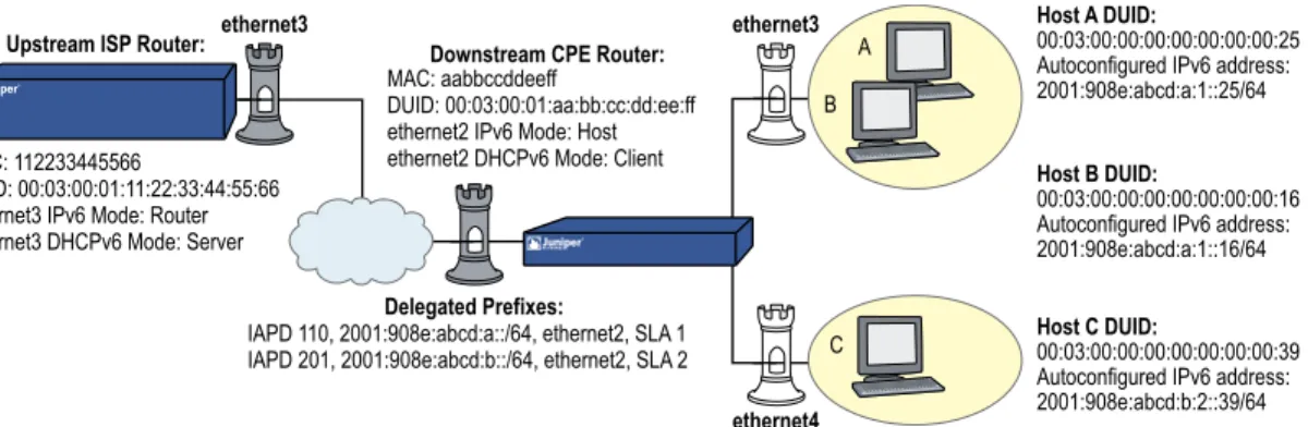
Figure 10: DHCPv6 Prefix Delegation . . . 39
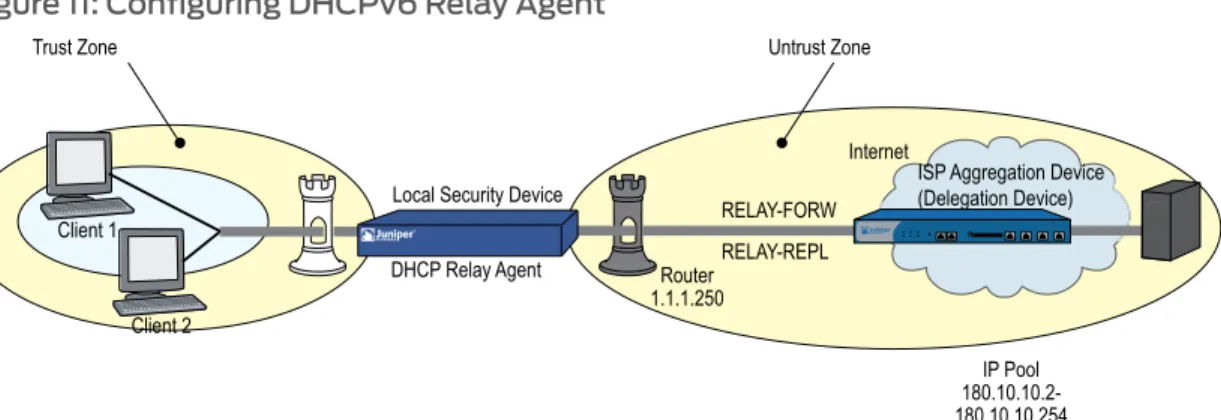
Figure 11: Configuring DHCPv6 Relay Agent . . . 42
Figure 12: Domain Name System Servers . . . 45
Figure 13: DNS Servers and DHCPv6 Client . . . 46
Figure 14: Proxy DNS Using Split Servers . . . 48
Figure 15: PPPoE Client and Server . . . 50
Chapter 4 Static and Dynamic Routing . . . 53
Figure 16: Dual-Stack Router Behavior . . . 54
Figure 17: Tunnel Interface with RIPng Example . . . 70
Figure 18: RADIUSv6 IKE Example . . . 72
Chapter 5 Address Translation . . . 81
Figure 19: Network Address Translation (NAT) Across an IPv4/IPv6 Boundary . . . 81
Figure 20: DIP from IPv6 to IPv4 . . . 82
Figure 21: DIP from IPv4 to IPv6 . . . 83
Figure 22: MIP from IPv6 to IPv4 . . . 83
Figure 23: MIP from IPv4 to IPv6 . . . 84
Figure 24: IPv4-Mapped Addresses . . . 85
Figure 25: IPv6-to-IPv4 Host Mapping . . . 87
Figure 26: IPv4-to-IPv6 Network Mapping . . . 88
Figure 27: IPv4-to-IPv6 Host Mapping . . . 90
Chapter 6 IPv6 in an IPv4 Environment . . . 95
Figure 29: IPv6 Tunneling Using IPv4 Encapsulation Example . . . 96
Figure 30: 6to4 Routers . . . 99
Figure 31: 6to4 Routers with Native Addresses . . . 100
Figure 32: 6over6 Manual Tunneling . . . 100
Figure 33: 6to4 Tunnel . . . 104
Chapter 7 IPsec Tunneling . . . 107
Figure 34: IPsec with 6in6 Tunnel Example . . . 108
Figure 35: IPsec 4in6 Tunnel Example . . . 111
Figure 36: Tunnel Interface and Zone Example . . . 115
Figure 37: Manual Tunneling Example . . . 120
Chapter 8 IPv6 XAuth User Authentication . . . 127
Figure 38: RADIUS with a Single Client and Single Server . . . 128
Figure 39: RADIUS with Multiple Clients and a Single Server . . . 128
Figure 40: RADIUS with a Single Client and Multiple Servers . . . 129
Figure 41: RADIUS with Multiple Hosts and a Single Server . . . 129
Figure 42: IPsec Access Session with RADIUS Server . . . 130
Figure 43: XAuth Example . . . 133
Figure 44: IPsec Access Session Example . . . 149
Part 1
Dual-Stack Architecture with IPv6
Chapter 1 Internet Protocol Version 6 Introduction . . . 3
Table 1: IPv6 Header Fields, Length, and Purpose . . . 6
Chapter 2 IPv6 Configuration . . . 11
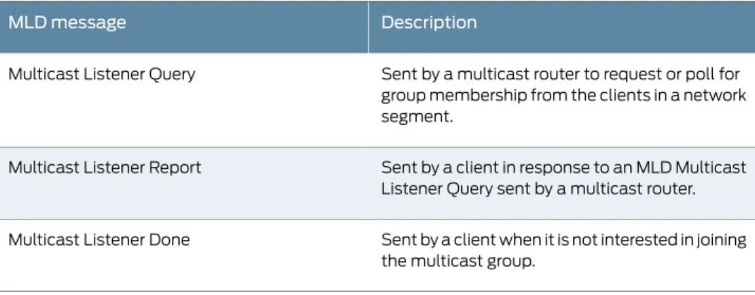
Table 2: Multicast Listener Discovery (MLD) Messages . . . 31
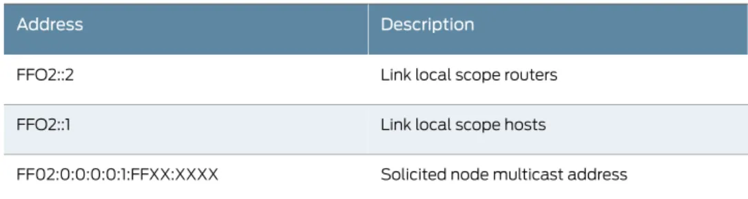
Table 3: Multicast Address . . . 32
Chapter 4 Static and Dynamic Routing . . . 53
Table 4: Global RIPng Parameters and Default Values . . . 58
Table 5: RIPng Interface Parameters and Default Values . . . 62
Part 2
Appendix
Table 6: Transparent Mode Commands to Bypass Non-IP Traffic . . . 163Appendix A Switching . . . 163
TheDual Stack Architecture with IPv6guide describes ScreenOS support for Internet Protocol version 6 (IPv6) and how to secure IPv6 and IPv4/IPv6 transitional networks with tunneling and IPsec.
Dual-stack architecture allows an interface to operate simultaneously in IPv4 and IPv6 modes and facilitates network management, while a network contains both IPv4 and IPv6 devices that pass traffic between IPv4/IPv6 boundaries.
This guide contains the following sections:
• “Internet Protocol Version 6 Introduction” on page 3explains IPv6 headers, concepts, and tunneling guidelines.
• “IPv6 Configuration” on page 11explains how to configure an interface for operation as an IPv6 router or host.
• “Connection and Network Services” on page 35explains how to configure Dynamic Host Configuration protocol version 6 (DHCPv6), Domain Name Services (DNS), Point-to-Point Protocol over Ethernet (PPPoE), and fragmentation.
• “Static and Dynamic Routing” on page 53explains how to set up static and dynamic routing. This chapter explains ScreenOS support for Routing Information Protocol-Next Generation (RIPng).
• “Address Translation” on page 81explains how to use Network Address Translation (NAT) with dynamic IP (DIP) and mapped-IP (MIP) addresses to traverse IPv4/IPv6 boundaries.
• “IPv6 in an IPv4 Environment” on page 95explains manual and dynamic tunneling.
• “IPsec Tunneling” on page 107explains how to configure IPsec tunneling to connect dissimilar hosts.
• “IPv6 XAuth User Authentication” on page 127explains how to configure Remote Authentication Dial In User Service (RADIUS) and IPsec Access Session (IAS) management.
• Switching lists options for using the security device as a switch to pass IPv6 traffic.
• Document Conventions on page xviii • Document Feedback on page xx
Document Conventions
This document uses the conventions described in the following sections:
• Web User Interface Conventions on page xviii • Command Line Interface Conventions on page xviii • Naming Conventions and Character Types on page xix • Illustration Conventions on page xix
Web User Interface Conventions
The Web user interface (WebUI) contains a navigational path and configuration settings. To enter configuration settings, begin by clicking a menu item in the navigation tree on the left side of the screen. As you proceed, your navigation path appears at the top of the screen, with each page separated by angle brackets.
The following example shows the WebUI path and parameters for defining an address: Policy > Policy Elements > Addresses > List > New: Enter the following, then clickOK:
Address Name: addr_1 IP Address/Domain Name: IP/Netmask: (select), 10.2.2.5/32 Zone: Untrust
To open Online Help for configuration settings, click the question mark (?) in the upper right of the screen.
The navigation tree also provides a Help > Config Guide configuration page to help you configure security policies and Internet Protocol Security (IPSec). Select an option from the list, and follow the instructions on the page. Click the?character in the upper right for Online Help on the Config Guide.
Command Line Interface Conventions
The following conventions are used to present the syntax of command line interface (CLI) commands in text and examples.
In text, commands are inboldfacetype and variables are initalictype.
In examples:
• Variables are initalictype.
• Anything inside square brackets [ ] is optional.
• Anything inside braces { } is required.
• If there is more than one choice, each choice is separated by a pipe ( | ). For example, the following command means “set the management options for the ethernet1, the ethernet2,orthe ethernet3 interface”:
NOTE: When entering a keyword, you only have to type enough letters to identify the word uniquely. Typingset adm u whee j12fmt54will enter the commandset admin user wheezer j12fmt54. However, all the commands documented in this guide are presented in their entirety.
Naming Conventions and Character Types
ScreenOS employs the following conventions regarding the names of objects—such as addresses, admin users, auth servers, IKE gateways, virtual systems, VPN tunnels, and zones—defined in ScreenOS configurations:
• If a name string includes one or more spaces, the entire string must be enclosed within double quotes; for example:
set address trust “local LAN” 10.1.1.0/24
• Any leading spaces or trailing text within a set of double quotes are trimmed; for example,“ local LAN ”becomes“local LAN”.
• Multiple consecutive spaces are treated as a single space.
• Name strings are case-sensitive, although many CLI keywords are case-insensitive. For example,“local LAN”is different from“local lan”.
ScreenOS supports the following character types:
• Single-byte character sets (SBCS) and multiple-byte character sets (MBCS). Examples of SBCS are ASCII, European, and Hebrew. Examples of MBCS—also referred to as double-byte character sets (DBCS)—are Chinese, Korean, and Japanese.
• ASCII characters from 32 (0x20 in hexadecimals) to 255 (0xff), except double quotes ( “ ), which have special significance as an indicator of the beginning or end of a name string that includes spaces.
NOTE: A console connection only supports SBCS. The WebUI supports both SBCS and MBCS, depending on the character sets that your browser supports.
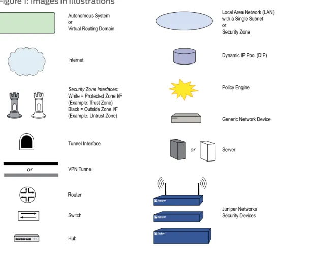
Illustration Conventions
Figure 1 on page xxshows the basic set of images used in illustrations throughout this guide.
Figure 1: Images in Illustrations
Document Feedback
If you find any errors or omissions in this document, contact Juniper Networks at
Requesting Technical Support
Technical product support is available through the Juniper Networks Technical Assistance Center (JTAC). If you are a customer with an active J-Care or JNASC support contract, or are covered under warranty, and need postsales technical support, you can access our tools and resources online or open a case with JTAC.
• JTAC policies—For a complete understanding of our JTAC procedures and policies, review theJTAC User Guidelocated at
http://www.juniper.net/customers/support/downloads/710059.pdf.
• Product warranties—For product warranty information, visit
http://www.juniper.net/support/warranty/.
• JTAC hours of operation—The JTAC centers have resources available 24 hours a day, 7 days a week, 365 days a year.
Self-Help Online Tools and Resources
For quick and easy problem resolution, Juniper Networks has designed an online self-service portal called the Customer Support Center (CSC) that provides you with the following features:
• Find CSC offerings—http://www.juniper.net/customers/support/ • Find product documentation—http://www.juniper.net/techpubs/
• Find solutions and answer questions using our Knowledge Base—http://kb.juniper.net/ • Download the latest versions of software and review your release
notes—http://www.juniper.net/customers/csc/software/ • Search technical bulletins for relevant hardware and software
notifications—http://www.juniper.net/alerts/
• Join and participate in the Juniper Networks Community Forum—http://www.juniper.net/company/communities/
• Open a case online in the CSC Case Manager—http://www.juniper.net/customers/cm/ • To verify service entitlement by product serial number, use our Serial Number
Entitlement (SNE) Tool—https://tools.juniper.net/SerialNumberEntitlementSearch/
Opening a Case with JTAC
You can open a case with JTAC on the Web or by telephone.
• Use the Case Manager tool in the CSC athttp://www.juniper.net/customers/cm/.
• Call 1-888-314-JTAC (1-888-314-5822—toll free in USA, Canada, and Mexico).
For international or direct-dial options in countries without toll-free numbers, visit us at
• Internet Protocol Version 6 Introduction on page 3 • IPv6 Configuration on page 11
• Connection and Network Services on page 35 • Static and Dynamic Routing on page 53 • Address Translation on page 81
• IPv6 in an IPv4 Environment on page 95 • IPsec Tunneling on page 107
ScreenOS supports Internet Protocol version 6 (IPv6), developed by the Internet Engineering Task Force (IETF).
NOTE: Some security devices support IPv6. Check the datasheet for your security platform to determine which features it supports.
This chapter contains the following sections:
• Overview on page 3 • IPv6 Addressing on page 4 • IPv6 Headers on page 6 • IPv6 Packet Handling on page 8 • IPv6 Router and Host Modes on page 9 • IPv6 Tunneling Guidelines on page 9
Overview
By using addressing and schema that are different from IPv4, IPv6 allows a greater number of connected hosts than IPv4 can allow. In addition, IPv6 reduces packet processing overhead and increases network scalability. Together, these improvements allow a greater exchange of data traffic.
IPv6 provides for interoperability between IPv4 devices and IPv6 devices. It is usually possible to install IPv6 on security devices without losing IPv4 capability, so organizations can perform incremental upgrades and avoid service disruptions while migrating from IPv4 to IPv6.
NOTE: For more information about IPv6, refer to RFC 2460.
ScreenOS features dual-stack architecture, which allows an interface to operate simultaneously in IPv4 and IPv6 modes. Dual-stack architecture allows you to secure your network infrastructure while it contains both IPv4 and IPv6 devices and to secure traffic that passes across IPv4/IPv6 boundaries.
Each IPv6-enabled security device can operate as an IPv6 host or router.
IPv6 Addressing
IPv6 addresses differ from IPv4 addresses in several ways:
• Notation
• Prefixes
• Address Types
These differences give IPv6 addressing greater simplicity and scalability than IPv4 addressing.
Notation
IPv6 addresses are 128 bits long (expressed as 32 hexadecimal numbers) and consists of eight colon-delimited sections. Each section contains 2 bytes, and each byte is expressed as a hexadecimal number from 0 to FF.
An IPv6 address looks like this:
2080:0000:0000:0000:0008:0800:200c:417a
By omitting the leading zeroes from each section or substituting contiguous sections that contain zeroes with a double colon, you can write the example address as:
2080:0:0:0:8:800:200c:417a or 2080::8:800:200c:417a
For example, 0000:0000:0000:0000:0000:0000:93fc:9303 can be written as ::93fc:9303.
You can use the double-colon delimiter only once within a single IPv6 address. For example, you cannot express the IPv6 address 32af:0:0:0:ea34:0:71ff:fe01 as 32af::ea34::71ff:fe01.
Prefixes
Each IPv6 address contains bits that identify a network and a node or interface. An IPv6 prefix is the portion of an IPv6 address that identifies the network. The prefix length is a positive integer that denotes a number of consecutive bits, beginning with the most significant (left-most) bit. The prefix length follows a forward slash and, in most cases, identifies the portion of the address owned by an organization. All remaining bits (up to the right-most bit) represent individual nodes or interfaces.
For example, 32f1::250:af:34ff:fe26/64 has a prefix length of 64.
The first 64 bits of this address are the prefix (32f1:0000:0000:0000). The rest (250:af:34ff:fe26) identifies the interface.
Address Types
• Unicast
• Anycast
• Multicast
Unicast Addresses
A unicast address is an identifier for a single interface. When a network device sends a packet to a unicast address, the packet goes only to the specific interface identified by that address.
Devices use the following types of unicast addresses:
• A global unicast address is a unique IPv6 address assigned to a host interface. Global unicast addresses serve essentially the same purposes as IPv4 public addresses. Global unicast addresses are aggregatable for efficient and hierarchical addressing.
• A 6to4 address enables an IPv6 host interface for 6to4 tunneling. A 6to4 interface can serve as a border router between the host and IPv4 network space. In most cases, this method is not suitable for performing IPsec operations such as authentication and encryption.
• A link-local IPv6 address allows communication between neighboring hosts that reside on the same link. The device automatically generates a link-local address for each configured IPv6 interface.
• An IPv4-mapped address is a special IPv6 address that is the equivalent of an IPv4 address. A device uses IPv4-mapped addresses for address translation, when the device must send traffic from an IPv6 network to an IPv4 network.
Anycast Addresses
An anycast address is an identifier for a set of interfaces, which typically belongs to different nodes. When a network device sends a packet to an anycast address, the packet goes to one of the interfaces identified by that address. The routing protocol used in the network usually determines which interface is physically closest within the set of anycast addresses and routes the packet along the shortest path to its destination.
For more information about anycast addresses, refer to RFC 2526.
Multicast Addresses
A multicast address is an identifier for a set of interfaces, which typically belongs to different nodes. When a network device sends a packet to a multicast address, the device broadcasts the packet to all interfaces identified by that address.
Devices use the following types of multicast addresses:
• Solicited-node multicast addresses for Neighbor Solicitation (NS) messages.
• All-nodes multicast address for Router Advertisement (RA) messages.
IPv6 Headers
The IETF designed IPv6 headers for low overhead and scalability. IPv6 headers allow optional extension headers, which contain extra information usable by network devices.
Basic Header
Every IPv6 packet has a basic IPv6 header. IPv6 headers occupy 40 bytes (320 bits).
Figure 2 on page 6shows each field, arranged in order.
Figure 2: Header Structure
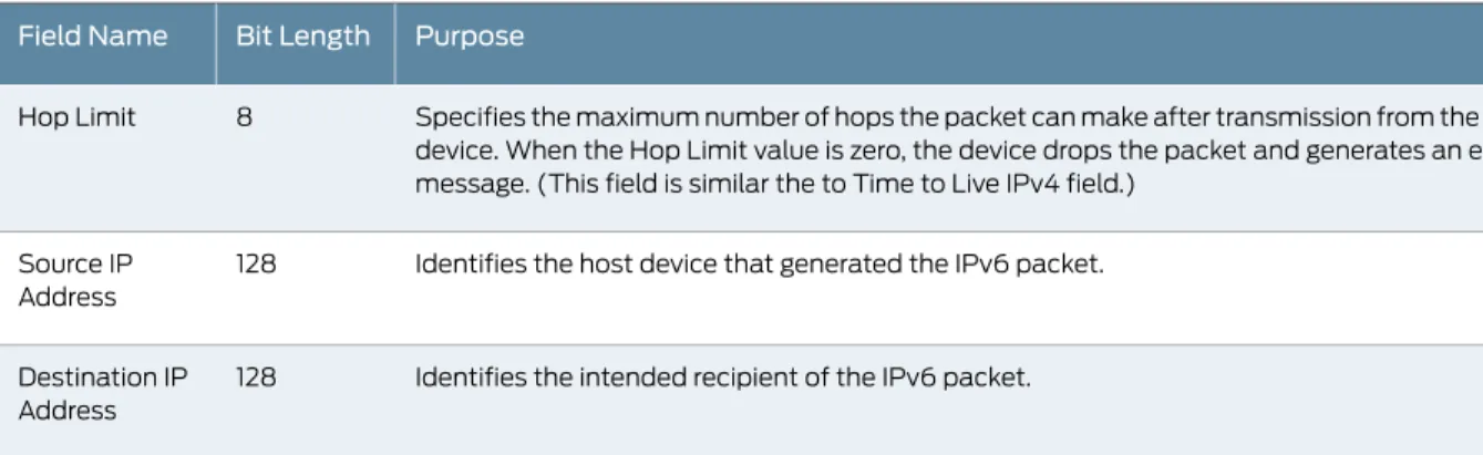
Table 1 on page 6lists the fields with bit lengths and their purposes.
Table 1: IPv6 Header Fields, Length, and Purpose
PurposeBit Length Field Name
Specifies the Internet Protocol used by the header and packet. This value tells destination internet devices which IP stack (IPv4 or IPv6) to use when processing the packet header and payload. IPv6 Version fields contain a value of 6. (IPv4 Version fields contain a value of 4.) 4
Version
Allows source nodes or routers to identify different classes (or priorities) of IPv6 packets. (This field replaces the IPv4 Type of Service field, which identified categories of packet transfer services.)
8 Traffic Class
Identifies the flow to which the packet belongs. Packets in a flow share a common purpose, or belong to a common category, as interpreted by external devices such as routers or destination hosts. Typically, the source host inserts Flow Label values into outgoing packets to request special handling by the external devices. The external devices can uniquely identify each flow by evaluating the source address in combination with the Flow Label value. Traffic transmitted by a source host can contain packets in a single flow, multiple flows, no flow, or any combination. (Packets that do not belong to a flow carry a Flow Label of zero.) 20
Flow Label
Specifies the length of the of the IPv6 packet payload, expressed in octets. 6
Payload Length
Identifies the type of IP protocol for the header that immediately follows the IPv6 header. This protocol can be one of two types:
• An IPv6 extension header. For example, if the device performs IPsec security on exchanged packets, the Next Header value is probably 50 (ESP extension header) or 51 (AH extension header). Extension headers are optional.
• An upper-layer Protocol Data Unit (PDU). For example, the Next Header value could be 6 (for TCP), 17 (for UDP), or 58 (for ICMPv6).
The Next Header field replaces the IPv4 Protocol field. It is an optional field. 8
Table 1: IPv6 Header Fields, Length, and Purpose
(continued)
Purpose Bit Length
Field Name
Specifies the maximum number of hops the packet can make after transmission from the host device. When the Hop Limit value is zero, the device drops the packet and generates an error message. (This field is similar the to Time to Live IPv4 field.)
8 Hop Limit
Identifies the host device that generated the IPv6 packet. 128
Source IP Address
Identifies the intended recipient of the IPv6 packet. 128
Destination IP Address
Extension Headers
Extension headers contain supplementary information used by network devices (such as routers, switches, and endpoint hosts) to decide how to direct or process an IPv6 packet. The length of each extension header is an integer multiple of eight octets. This allows subsequent extension headers to use 8-octet structures.
Any header followed by an extension header contains a Next Header value that identifies the extension header type.
Extension headers always follow the basic IPv6 header in order as follows:
1. The Hop-by-Hop Options header specifies delivery parameters at each hop on the path to the destination host. When a packet uses this header, the Next Header value of the previous header (the basic IPv6 header) must be 0.
2. The Destination Options header specifies packet delivery parameters for either intermediate destination devices or the final destination host. When a packet uses this header, the Next Header value of the previous header must be 60.
3. The Routing header defines strict source routing and loose source routing for the packet. (With strict source routing, each intermediate destination device must be a single hop away. With loose source routing, intermediate destination devices can be one or more hops away.) When an packet uses this header, the Next Header value of the previous header must be 43.
The firewall can block packets that have a routing header of type 0. To avoid blocking all routing headers, configure the routing header type filters using the following command: set service <name>protocol routing-ext-hdr type<value>.
4. The Fragment header specifies how to perform IPv6 fragmentation and reassembly services. When a packet uses this header, the Next Header value of the previous header must be 44.
5. The Authentication header provides authentication, data integrity, and anti-replay protection. When a packet uses this header, the Next Header value of the previous header must be 51.
6. The Encapsulating Security Payload header provides data confidentiality, data authentication, and anti-replay protection for encapsulated security payload (ESP)
packets. When a packet uses this header, the Next Header value of the previous header must be 50.
7. To filter or deny the extension header with a user-defined service, define the src-port and dst-port as wildcard 0-65535.
IPv6 Packet Handling
An interface configured for dual-stack operation provides both IPv4 and IPv6 capability. Such an interface can have an IPv4 address, at least one IPv6 address, or both.
If the interface resides at the boundary between an IPv4 network and an IPv6 network, the device can pass IP traffic over the boundary in one of two ways:
• Encapsulate (effectively hiding) any packet that passes across the boundary.
• Perform address translation on the packet source and destination addresses.
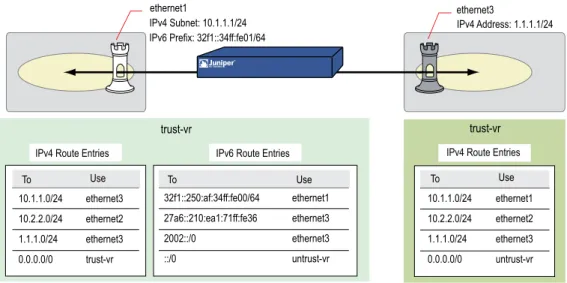
Figure 3 on page 8shows a packet-handling flow that might occur when an IPv6 host passes an outgoing service request packet across the IPv6/IPv4 boundary into an IPv4 network space.
Figure 3: Packet Flow Across IPv6/IPv4 Boundary
IPv6 IPv4
Boundary ethernet1
IPv6 prefix: 32f1::34ff:fe01 IPv4 address and mask:
10.1.1.1/24
ethernet3 IPv4 address and
mask: 1.1.1.1/24
Untrust Trust
1. An IPv6 host transmits a service request packet. The source and destination addresses use IPv6 format.
2. IPv6 interface ethernet1 receives the packet.
3. The security device applies a policy to the packet. It either encapsulates the entire packet inside an IPv4 packet or translates the addresses to IPv4 format.
4. IPv4 interface ethernet3 transmits the packet (now using IPv4 address format).
5. A remote gateway node receives the packet.
• If encapsulation occurred, the device might de-encapsulate the packet or continue to treat it as an IPv4 packet.
• If IPv6/IPv4 address translation occurred, the device might translate the addresses back to IPv6 format or continue to treat the packet as an IPv4 packet.
IPv6 Router and Host Modes
You can configure each interface in a security device to function as an IPv6 host or router.
• In host mode, the interface functions as an IPv6 host and autoconfigures itself by requesting and accepting Router Advertisement (RA) messages from other devices.
• In router mode, the interface functions as an IPv6 router. An IPv6 router replies to Router Solicitation (RS) messages from IPv6 hosts by sending RAs. In addition, the interface can broadcast RAs periodically or in response to configuration changes to keep the on-link hosts updated.
IPv6 Tunneling Guidelines
Before deciding which kind of tunneling to use, ask your upstream ISP which IPv6 services they provide and how they provide them. We recommend the following guidelines:
• If your ISP provides only dual-stack IPv6, which is Internet Protocol Control Protocol (IPCP) and IPv6CP, you should configure run dual-stack, native IPv6. 6to4 addressing format is not appropriate in this case.
• If your ISP provides manual tunnel IPv6 (IPv6-over-IPv4 tunnel), you should use manual tunneling.
• If your ISP does not provide IPv6, go towww.hexago.com/to find an upstream IPv6 provider, and follow their posted instructions.
For updates and service information about IPV6, visit one of the following websites:
• http://www.ipv6day.org/ • http://www.ipv6tf.org/ • http://www.ipv6forum.com/
NOTE: The above references are provided as effective resources as of the publication date of this document. However, we encourage administrators to seek out their own IPv6 references, which might be more current.
If you do not find an IPv6 provider, use 6to4 tunneling. This option, however, is only feasible if the next-hop router is configured for it.
This chapter explains how to enable IPv6 features on the security device and how to configure the security device to act as an Internet Protocol version 6 (IPv6) router or IPv6 host.
This chapter contains the following sections:
• Overview on page 11
• Enabling an IPv6 Environment on page 18 • Configuring an IPv6 Host on page 19 • Configuring an IPv6 Router on page 21
• Viewing IPv6 Interface Parameters on page 30 • Multicast Listener Discovery Protocol on page 31 • Configuration Examples on page 33
Overview
ScreenOS allows you to configure a security device to be an IPv6 router or an IPv6 host. This overview explains the following topics:
• Address autoconfiguration
• Neighbor discovery
The sections following the overview explain how to configure an IPv6 host or router.
Address Autoconfiguration
Address autoconfiguration allows local hosts to autoconfigure IPv6 addresses from their extended unique identifier (EUI) values. A security device configured for address autoconfiguration advertises an IPv6 prefix to local IPv6 hosts. The local hosts use this prefix to autoconfigure IPv6 addresses from their EUI values.
Address autoconfigurationreduces the need to manually assign addresses to individual hosts. Ideally, IPv6 hosts have address autoconfiguration enabled. An interface, configured to operate as an IPv6 router, can enable local on-link IPv6 hosts to perform
autoconfiguration. Autoconfiguration does not require a stateful configuration protocol, such as Dynamic Host Configuration Protocol version 6 (DHCPv6).
Extended Unique Identifier
An EUI address is a 64-bit hex interface identifier. If you do not specify an EUI value explicitly, the security device autogenerates it from the MAC address of the IPv6 interface. This usually happens immediately the first time you define an IPv6 interface.
A device configured for address autoconfiguration advertises an IPv6 prefix to local IPv6 hosts. The local hosts use this prefix to autoconfigure IPv6 addresses from their EUI-ID values.
NOTE: For more information about EUI, refer to Guidelines for 64-Bit Global Identifier (EUI-64) Registration Authority at
http://standards.ieee.org/regauth/oui/tutorials/EUI64.html
Router Advertisement Messages
A Router Advertisement (RA) is a message sent by a router to on-link hosts periodically or in response to a Router Solicitation (RS) request from another host. The
autoconfiguration information in an RA includes the following:
• IPv6 prefixes of the IPv6 router, which allow the on-link hosts to access the router
• Maximum Transmission Unit (MTU), which informs the on-link hosts the maximum size (in bytes) of exchanged packets
• Specific routes to the router, which allow the on-link hosts to send packets through the router
• Whether or not to perform IPv6 address autoconfiguration and, when appropriate, a prefix list
• Period that autoconfigured addresses remain valid and preferred
Router Solicitation Messages
A Router Solicitation (RS) is a message sent by hosts to discover the presence and properties of on-link routers. When an IPv6 router receives an RS request from a host, it responds by transmitting an RA message back to the host. An RA announces the existence of the router and provides the host with the information it needs to perform
autoconfiguration tasks.
Each RS contains the link-local address of the source host. The host derives the link-local address from its MAC address. When the IPv6 router receives the RS, it uses the link-local address to transmit an RA back to the host.
Prefix Lists
A prefix listis a table containing IPv6 prefixes. When entries are present in the list, the router includes them in the RAs it sends to on-link hosts. Each time a host receives an RA, it can use the prefixes to perform address autoconfiguration.Figure 4 on page 13
shows Host A and Host B using three prefixes to generate unique global aggregatable addresses.
Figure 4: Address Autoconfiguration
Zone A Zone B
Link-Local Address: fe80::9876:dcff:feba:5432 Autoconfigured Global Addresses: 2bfc::9876:dcff:feba:5432 3afc::9876:dcff:feba:5432 2caf::9876:dcff:feba:5432 Link-Local Address: fe80::1234:abff:fecd:5678 Autoconfigured Global Addresses: 2bfc::1234:abff:fecd:5678 3afc::1234:abff:fecd:5678 2caf::1234:abff:fecd:5678 Prefix List 2bfc::0/64 3afc::0/64 2caf::0/64
Host B MAC Address: 9876.dcba.5432 Host A MAC Address: 1234.abcd.5678
RS RA
1. On startup, IPv6 Hosts A and B generate link-local addresses from their MAC addresses.
2. Each host broadcasts RS messages. Each message uses the host link-local address as the source address for the RS packets.
3. The IPv6 router receives the RS message.
4. The IPv6 router transmits confirming RA messages to the hosts. These messages contain a prefix list.
5. The hosts use the prefixes to perform autoconfiguration.
Neighbor Discovery
Neighbor Discovery (ND) is the process of tracking the reachability status for neighbors in a local link. A device views a neighbor as reachable when the device receives recent confirmation that the neighbor received and processed IP traffic or Neighbor Solicitation (NS) requests. Otherwise, it considers the neighbor unreachable. Although not explicitly required, IPv6 host might have ND enabled. An IPv6 router with ND enabled can send ND information downstream.
Neighbor Cache Table
The Neighbor Cache table contains information about neighbors to which hosts have recently sent traffic. In addition, the table tracks the current reachability status of neighbors on the local link. Each entry contains the following information:
• IPv6 address of the neighbor
• MAC address of the neighbor
• Current neighbor reachability state
• Age of the neighbor entry
Table entries are keyed on the IPv6 address. All entries are synced to the backup device in an NSRP cluster. When device failover occurs, the backup device becomes the primary and sends the NDP packet to the neighbor host to notify it of the change.
Neighbor Unreachability Detection
Neighbor Unreachability Detection (NUD) works by building and maintaining a Neighbor Cache table, which contains the address for each neighbor to which a host has recently sent traffic. The device uses these entries to record changes in the reachability status of the neighbors. NUD allows the device to track the changing reachability state of each neighbor and to make traffic-forwarding decisions.
Neighbor Entry Categories
A Neighbor Cache table entry can belong to any of four categories. The category of the entry determines how the device generates the entry initially and manages reachability states thereafter.
• Endpoint host entries:When an endpoint host makes an initial attempt to send traffic to a neighbor, the device automatically generates a corresponding entry in the Neighbor Cache table. The device uses this entry for further communication and to track the reachability state of the endpoint host.
• Next-hop gateway router entries:When you create a virtual routing table entry in a device for a gateway router, the device automatically generates a corresponding entry in the Neighbor Cache table. The device uses this entry for further communication and to track the reachability state of the gateway router.
• Manual tunnel gateway interface entries: When you set up a manual IPv6 over IPv4 tunnel interface, the device automatically generates an entry for the interface. This entry has an IPv6 link-local address. The device uses this entry to monitor the reachability state of the tunnel.
• For information about IPv6 over IPv4 tunneling, see“IPsec 6in4 Tunneling” on page 115.
• For information about link-local addresses, see“Configuring Manual Tunneling” on page 96.
• For information about tunnel gateway transitions, see“Tunnel Gateway State Transitions” on page 17.
• Static entries: When you create a Neighbor Cache entry statically, the device does not use it to perform ND or NUD operations. Instead, it assigns the entry a special
reachability state called Static. This enables the entry in all circumstances. While the entry exists, the device forwards any traffic sent to the represented neighbor.
Neighbor Reachability States
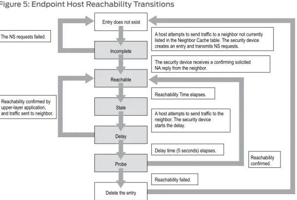
No Neighbor Cache entry exists for a neighbor until the device sends the neighbor an initial NS request. Until this happens, the device does not recognize the existence of the neighbor. When the device sends the initial request, it creates a table entry and sets it to the Incomplete state.
• Incomplete:A host attempted to send traffic to a neighbor currently unknown to the device, and initial address resolution is still in progress. The device broadcasts an NS request (using a solicited node multicast address) to find the neighbor, but has not yet received a confirming Neighbor Advertisement (NA).
The Incomplete state has different characteristics when the neighbor is a next-hop gateway router. For more information, see“Next-Hop Gateway Router State Transitions” on page 16.
• Reachable:The device currently considers the neighbor reachable because it received a confirming NA reply from the neighbor. While the entry state is Reachable, the device forwards any traffic sent to the neighbor. The entry state remains Reachable until the Reachable Time interval (expressed in seconds) elapses. Then the state changes to Stale.
• Stale:The device considers the neighbor unreachable because the Reachable Time interval has elapsed since the most recent NA from the neighbor. However, the device makes no attempt to verify reachability until a host attempts to send more traffic to the neighbor.
• Delay:A host attempted to send traffic to the neighbor while the state was Stale. The device makes no active attempt to verify neighbor reachability. Instead, it waits for upper-layer protocols to provide reachability confirmation. The device maintains the Delay state for five seconds. If the device receives confirmation during this delay period, the state changes to Reachable. Otherwise, the state changes to Probe.
• Probe:The Delay period elapsed, and the device received no confirmation from the upper-layer application. The device sends up to two unicast NS probes to verify reachability. If the device receives an NA message from the neighbor, the state changes to Reachable. Otherwise, the device deletes the reachability entry from the table. In effect, removal of a neighbor entry makes the device view the neighbor as nonexistent.
• Probe Forever:The device no longer considers the neighbor reachable, has made an attempt to forward traffic to the neighbor, and is sending unicast NS probes to verify reachability. The device continues to retransmit the probes indefinitely or until it receives a reachability confirmation from the neighbor.
The device uses the Probe Forever reachability stateonlywhen the entry represents a next-hop gateway router.
NOTE: The Neighbor Cache entry might also exist in Active and Inactive states but only when the neighbor is a manual IPv6in4 tunnel gateway interface.
How Reachability State Transitions Occur
A device changes the reachability state of a Neighbor Cache entry depending on the neighbor category, the current state of the entry, and whether on-link hosts attempt to send traffic to the neighbor.
Endpoint Host State Transitions
When an on-link host attempts to send traffic to a neighbor, the device searches the Neighbor Cache table for a corresponding Neighbor Cache table entry. If no entry exists, the device broadcasts an NS message for the neighbor. It then creates a new table entry and assigns it an Incomplete state.
Figure 5 on page 16shows how the device handles reachability state transitions after it generates a Neighbor Cache entry.
Figure 5: Endpoint Host Reachability Transitions
Next-Hop Gateway Router State Transitions
When you create a routing table entry to an IPv6 next-hop gateway router, the device automatically generates a corresponding Neighbor Cache table entry and assigns it an Incomplete state.
Figure 6 on page 17shows how the device handles reachability state transitions after it generates the Neighbor Cache entry for the first time.
Figure 6: Next-Hop Gateway Router Reachability Transitions
When you remove a router from which the device generated a Neighbor Cache table entry, the device deletes the entry automatically.
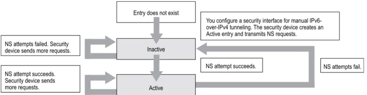
Tunnel Gateway State Transitions
When you configure an interface for manual IPv6-in-IPv4 tunneling, the device automatically generates a corresponding entry in the Neighbor Cache table. A device uses two entry states (also known as heartbeat states).
• Inactive:The device does not consider the neighbor reachable and has sent an NS message to test for reachability.
• Active:The device considers the neighbor reachable and periodically sends NS messages to confirm reachability.
When you create the IPv6-over-IPv4 tunnel, the device generates the Neighbor Cache entry and assigns it the Inactive state.Figure 7 on page 18shows how the device handles reachability state transitions after initial generation of the entry.
Figure 7: Tunnel Gateway State Transitions
When you remove the manual tunnel from which the device generated the Neighbor Cache Table entry, the device deletes the entry automatically.
For information about manual IPv6 over IPv4 tunneling, see“IPsec Tunneling” on page 107.
Static Entry Transitions
When you create a static entry, the device always forwards traffic transmitted to the neighbor because no NUD operations apply.
Figure 8: Static Entry State Transitions
Enabling an IPv6 Environment
To set up a security device for IPv6 operation, you must first enable an IPv6 environment variable on the device. You must complete this step otherwise you cannot view IPv6 features or options in the WebUI or the CLI.
Enabling IPv6 at the Device Level
To enable a device for IPv6, you must start a CLI session with the device. You can establish CLI sessions using software that emulates a VT100 terminal, such as Telnet or Secure Command Shell (SSH). If you make a direct connection through the console port, you can use HyperTerminal. (For more information about establishing CLI sessions, refer to the installation and configuration guide for the security device.
To check the IPv6 status of the security device, enter the following command:
get envar
If the device is currently IPv6-enabled, the following appears in the console output:
ipv6=yes
If this output does not appear, the device is not IPv6-enabled (default). To enable IPv6, enter the following commands:
set envar ipv6=yes save
reset save-config yes
When the confirmation prompt appears, entery.
Disabling IPv6 at the Device Level
You must start a CLI session with the device by establishing a console connection with HyperTerminal or another terminal emulation software.
To disable IPv6, enter the following commands:
unset envar ipv6 save
reset
When the confirmation prompt appears, entery.
Configuring an IPv6 Host
After enabling the device for IPv6 operation, you can configure the device to be an IPv6 host by performing the following steps:
1. Bind the interface to a zone (such as Trust, Untrust, or a user-defined zone).
2. Enable the mode and interface.
3. Configure address autoconfiguration.
4. Configure neighbor discovery.
The following sections describe ScreenOS settings pertinent to IPv6 host configuration.
NOTE: Optionally, in addition to an IPv6 address, the security device can have an IPv4 IP address associated with the same interface. For information about IPv4 interface configuration, see Fundamentals.
Binding the IPv6 Interface to a Zone
You can bind an interface to a custom or preset security zone with the WebUI or the CLI. Interface naming varies by platform. To view the interfaces on your security device you can use theget interfacecommand .
In the following example, you bind an interface named ethernet1/2 to the trust zone.
WebUI
Network > Interfaces: SelectEditto change the zone binding for an existing interface entry or clickNewto configure a new interface entry.
CLI
set interface ethernet1/2 zone trust save
Enabling IPv6 Host Mode
You can enable IPv6 modes from the WebUI or the CLI. The mode options are: none (not using IPv6), host, or router.
WebUI
Network > Interfaces: SelectEditto change the IPv6 mode for an existing interface entry or clickNewto configure a new interface entry. SelectHostmode.
Network > Interfaces > Edit (for ethernet1) > IPv6
CLI
set interface ethernet1/2 ipv6 mode host set interface ethernet1/2 ipv6 enable save
Setting an Interface Identifier
You can configure the Extended Unique Identifier (EUI) for the interface. The EUI is a 64-bit hexadecimal extension of the Ethernet Media Access Control (MAC) address. The device uses this value to autoconfigure an IPv6 link-local IP address for the interface.
WebUI
Network > Interfaces: SelectEditto change the zone binding for an existing interface entry, or clickNewto configure a new interface entry. Enter anInterface ID.
CLI
set interface ethernet1/2 ipv6 interface-id 0210dbfffe7ac108 save
Configuring Address Autoconfiguration
When you define a prefix list entry for address autoconfiguration, IPv6 on-link hosts can use the prefix to generate unique IPv6 addresses. In the following example, you define prefix list entry 2bfc::0/64.
WebUI
Network > Interfaces > Edit (for IPv6 interface) > Prefix lists: Enter the following, then clickOK:
New IPV6 Prefix/Length: 2bfc::0/64 Prefix Flags
Autonomous: (select) Onlink (select) CLI
set interface ethernet3 ipv6 ra prefix 2bfc::0/64 autonomous onlink
After you make this setting, the device automatically includes the prefix in any Router Advertisement (RA) messages sent to on-link hosts.
Configuring Neighbor Discovery
To direct the interface to discover the existence and identity of other routers, you can enable the Accept Incoming RAs setting for the IPv6 interface. With this setting enabled, the interface accepts RA messages from other IPv6 peer devices.
WebUI
Network > Interfaces > Edit (for IPv6 interface): Enter the following, then clickOK:
Accept Incoming Router Advertisements: (select) CLI
set interface ethernet3 ipv6 ra accept
After you enable this setting, the interface accepts any route advertisement it receives from another host in the link. When the interface receives such an advertisement, it stores the advertised IPv6 address and MAC address in the Neighbor Cache table.
To see if the interface received and stored any advertised routes, you can view the contents of the NDP table by executing the following command:
get ndp
Configuring an IPv6 Router
To configure an IPv6 router, perform the following steps:
1. Enable the IPv6 environment on the device.
2. Bind the interface to a zone (such as Trust, Untrust, or a user-defined zone).
3. Enable the mode and interface.
4. Configure address autoconfiguration.
5. Configure Router Advertisement (RA) parameters.
6. Configure Neighbor Discovery (ND) parameters.
The following sections describe ScreenOS settings pertinent to IPv6 router configuration.
NOTE: Optionally, in addition to an IPv6 address, the security device can have an IPv4 address associated with the same interface. For information about IPv4 interface configuration, see Fundamentals.
Binding the IPv6 Interface to a Zone
You can bind an interface to a custom or preset security zone with the WebUI or the CLI. Interface naming varies by platform.
WebUI
Network > Interfaces: SelectEditto change the zone binding for an existing interface entry or clickNewto configure a new interface entry.
CLI
interface ethernet1/2 zone trust save
Enabling IPv6 Router Mode
You can enable IPv6 modes from the WebUI or the CLI. The mode options are: none (not using IPv6), host, or router.
WebUI
Network > Interfaces: SelectEditto change the IPv6 mode for an existing interface entry or clickNewto configure a new interface entry. SelectRoutermode.
Network > Interfaces > Edit (for ethernet1) > IPv6
CLI
set interface ethernet1/2 ipv6 mode router set interface ethernet1/2 ipv6 enable save
Setting an Interface Identifier
An IPv6 interface identifier sets the Extended Unique Identifier (EUI) for the interface. The EUI is a 64-bit hexadecimal extension of the Ethernet Media Access Control (MAC) address. The device uses this value to autoconfigure an IPv6 link-local IP address for the interface.
WebUI
Network > Interfaces: SelectEditto change the zone binding for an existing interface entry, or clickNewto configure a new interface entry. Enter anInterface ID.
CLI
set interface ethernet1/2 ipv6 interface-id 0210dbfffe7ac108 save
Setting Address Autoconfiguration
To set host autoconfiguration for an IPv6 router, you must do all of the following settings:
• Enable the Outgoing Router Advertisements.
• Disable the Managed Configuration Flag.
Outgoing Router Advertisements Flag
Enabling the Outgoing Router Advertisements flag allows the interface to send Router Advertisement (RA) messages to on-link hosts. After enabling this setting, the interface immediately broadcasts a route advertisement to hosts in the link. It also broadcasts an RA automatically when it receives a Router Solicitation (RS) from a host or when you change any RA setting on the interface.
In the following example, you enable the Allow RA Transmission setting.
WebUI
Network > Interfaces > Edit (for IPv6 interface): Enter the following, then clickOK:
Allow RA Transmission: (select)
CLI
set interface ethernet3 ipv6 ra transmit Managed Configuration Flag
Enabling the Managed Configuration flag directs local hosts to use a stateful address autoconfiguration protocol, such as DHCPv6, to generate host addresses.
Local hosts cannot perform stateless address autoconfiguration while this setting is enabled.
In the following example, you disable the Managed Configuration flag to allow autoconfiguration.
WebUI
Network > Interfaces > Edit (for IPv6 interface): Enter the following, then clickOK:
Managed Configuration Flag: (deselect)
CLI
unset interface ethernet3 ipv6 ra managed Other Parameters Configuration Flag
Enabling the Other Parameters Configuration flag directs local hosts to use a stateful address autoconfiguration protocol (DHCPv6) to configure parameters other than host addresses.
Local hosts cannot perform stateless address autoconfiguration while this setting is enabled.
In the following example, you disable the Other Parameters Configuration flag to allow autoconfiguration.
WebUI
Other Parameters Configuration Flag: (deselect)
CLI
unset interface ethernet3 ipv6 ra other
Disabling Address Autoconfiguration
To disable host autoconfiguration for an IPv6 router, you must do the following:
• Disable the Outgoing Router Advertisements setting so that on-link host can’t send router advertisements.
• Enable the Managed Configuration Flag to force the hosts to use a stateful addressing protocol, such as DHCPv6.
• Enable the Other Parameters Configuration Flag.
In the following example, you disable address autoconfiguration on an IPv6 router.
WebUI
Network > Interfaces > Edit (for IPv6 interface): Enter the following, then clickOK:
Allow RA Transmission: (deselect) Managed Configuration Flag: (select)
Other Parameters Configuration Flag: (select) CLI
unset interface ethernet3 ipv6 ra transmit set interface ethernet3 ipv6 ra managed set interface ethernet3 ipv6 ra other
Setting Advertising Time Intervals
Address autoconfiguration uses several advertised time interval parameters for IPv6 routers. These intervals determine the frequency of events or the lifetime of identified objects.
Advertised Reachable Time Interval
Enabling the Reachable Time setting instructs the interface to include the Reachable Time interval in outgoing RA messages. This interval tells on-link hosts how long in seconds to consider the IPv6 interface reachable after they receive an RA from the interface.
The interface bases the Reachable Time interval on the current Base Reachable Time setting. For information about the Base Reachable Time, see“Base Reachable Time” on page 29.
The interface uses this value while performing Neighbor Unreachability Detection (NUD). The security device builds and maintains a Neighbor Cache table, which contains the address for each neighbor to which a host has recently sent traffic. The device uses these entries to record changes in the reachability status of the neighbors. NUD allows the
device to track the changing reachability state of each neighbor and to make traffic-forwarding decisions accordingly.
WebUI
Network > Interfaces > Edit (for IPv6 interface): Enter the following, then clickOK:
Reachable Time: (select) CLI
set interface ethernet3 ipv6 ra reachable-time Advertised Retransmit Time Interval
Enabling the Retransmission Time instructs the interface to include the Retransmission Time interval in outgoing RA messages. This interval (expressed in seconds) is the time that elapses between retransmissions of NS messages.
For information about the Retransmission Time interval, see“Retransmission Time” on page 30.
The interface uses this value while performing NUD.
WebUI
Network > Interfaces > Edit (for IPv6 interface): Enter the following, then clickOK:
Retransmission Time: (select) CLI
set interface ethernet3 ipv6 ra retransmit-time Maximum Advertisement Interval
The Maximum Advertisement interval specifies the maximum number of seconds allowed between transmission of unsolicited multicast RAs from the IPv6 interface.
In the following example, you set the interval to 500 seconds.
WebUI
Network > Interfaces > Edit (for IPv6 interface): Enter the following, then clickOK:
Maximum Advertisement Interval: 500 CLI
set interface ethernet3 ipv6 ra max-adv-int 500 Minimum Advertisement Interval
The Minimum Advertisement interval setting specifies the minimum number of seconds allowed between transmission of unsolicited multicast RAs from the IPv6 interface. In the following example, you set the interval to 100 seconds.
WebUI
Minimum Advertisement Interval: 100 CLI
set interface ethernet3 ipv6 ra min-adv-int 100 Advertised Default Router Lifetime
The Default Router Lifetime setting specifies the number of seconds that hosts can identify the interface to be the default router, after the hosts receive the last RA from the interface.
In the following example, you set the lifetime to 1500 seconds.
WebUI
Network > Interfaces > Edit (for IPv6 interface): Enter the following, then clickOK:
Minimum Advertisement Interval: 1500 CLI
set interface ethernet3 ipv6 ra default-life-time 1500
Advertising Packet Characteristics
An RA can provide on-link host devices with information about packets exchanged through the IPv6 interface, including the link MTU and the hop limit.
Link MTU Value
Enabling the Link MTU flag directs the IPv6 interface to include the Link MTU field in RA messages. The Link MTU is the maximum size (in bytes) of any IPv6 packet sent by a host over a link.
NOTE: The default Link MTU value for Ethernet is 1500 bytes. The default for PPPoE is 1490 bytes. This value must be from 1280 to 1500. You can change the MTU value for some platforms. Refer to the documentation for your security device to see if you can configure the MTU value.
In the following example, you enable advertisement of the link MTU.
WebUI
Network > Interfaces > Edit (for IPv6 interface): Enter the following, then clickOK:
Link MTU: (select) CLI
set interface ethernet3 ipv6 ra link-mtu Current Hop Limit
The Current Hop Limit setting specifies the hop limit for packets sent by any local IPv6 host that uses RAs from this interface for address autoconfiguration. Setting the Current Hop Limit value to zero denotes an unspecified number of hops.