Unified Communications Using
Cisco BE 6000
TECHNOLOGY DESIGN GUIDE
February 2014
Table of Contents
Preface ...4
CVD Navigator ...5
Use Cases ... 5
Scope ... 5
Proficiency ... 5
Introduction ...1
Technology Use Case ... 1
Use Case: Centralized Unified Communications ... 1
Design Overview ... 3
Cisco Unified Computing System ... 3
Cisco Voice Gateways ... 3
Cisco Unified Communications ... 4
Single Cluster Centralized Design ... 4
Auto-Registration ... 7
Active Directory Integration ... 7
Dial Plan ... 8
Site Codes ... 8
Class of Service ... 9
Local Route Groups ... 10
Survivable Remote Site Telephony ...11
Device Mobility ...13
Extension Mobility ...13
Extend and Connect ...13
Media Resources ...13
Call Admission Control ...14
Point-to-Point Video ...14
IM and Presence ...14
Deployment Details ...17
Preparing the Network for IP Phones ...17
Phone Models ... 20
Network Preparation Summary ... 21
Preparing the Platform for Cisco Unified CM ... 21
Installing Cisco Unified CM ... 23
Preparing the Platform for Cisco Unity Connection ... 38
Installing Cisco Unity Connection ...41
Configuring Cisco Unified CM and Cisco Unity Connection ... 47
Configuring Users, Device Profiles, and IP Phones ... 63
Configuring Conference Bridges, PSTN, Dial Peers, and SRST ... 67
Configuring Extend and Connect ... 80
Preparing the Platform for Cisco Unified CM IM and Presence ... 86
Installing Cisco Unified CM IM and Presence ... 87
Configuring Services for Cisco Jabber IM and Cisco UC ... 96
Configuring Cisco Jabber for Windows ... 106
Preface
Cisco Validated Designs (CVDs) provide the foundation for systems design based on common use cases or current engineering system priorities. They incorporate a broad set of technologies, features, and applications to address customer needs. Cisco engineers have comprehensively tested and documented each CVD in order to ensure faster, more reliable, and fully predictable deployment.
CVDs include two guide types that provide tested and validated design and deployment details:
• Technology design guides provide deployment details, information about validated products and software, and best practices for specific types of technology.
• Solution design guides integrate or reference existing CVDs, but also include product features and functionality across Cisco products and may include information about third-party integration.
Both CVD types provide a tested starting point for Cisco partners or customers to begin designing and deploying systems using their own setup and configuration.
How to Read Commands
Many CVD guides tell you how to use a command-line interface (CLI) to configure network devices. This section describes the conventions used to specify commands that you must enter.
Commands to enter at a CLI appear as follows: configure terminal
Commands that specify a value for a variable appear as follows: ntp server 10.10.48.17
Commands with variables that you must define appear as follows: class-map [highest class name]
Commands at a CLI or script prompt appear as follows: Router# enable
Long commands that line wrap are underlined. Enter them as one command:
police rate 10000 pps burst 10000 packets conform-action set-discard-class-transmit 48 exceed-action set-discard-class-transmit
Noteworthy parts of system output or device configuration files appear highlighted, as follows: interface Vlan64
ip address 10.5.204.5 255.255.255.0
Comments and Questions
If you would like to comment on a guide or ask questions, please use the feedback form. For the most recent CVD guides, see the following site:
CVD Navigator
The CVD Navigator helps you determine the applicability of this guide by summarizing its key elements: the use cases, the scope or breadth of the technology covered, the proficiency or experience recommended, and CVDs related to this guide. This section is a quick reference only. For more details, see the Introduction.
Use Cases
This guide addresses the following technology use cases:
• Centralized Unified Communications—Organizations require high-quality voice and video communications that can scale up to thousand users using Cisco Business Edition 6000. They need a solution that is fast to deploy and easy to manage from a central location, without replicating costly features at their remote sites.
For more information, see the “Use Cases” section in this guide.
Scope
This guide covers the following areas of technology and products: • Unified communications applications, such as IP telephony
Voicemail and IM and Presence • Telephony call agent
• Voicemail server • IM & Presence Server • Virtualized servers
• Voice gateways and conference bridges • IP telephones with remote-site survivability • Session Initiation Protocol (SIP) signaling
• Lightweight Directory Access Protocol integration • Cisco Unified Configurator for Collaboration(CUCC) For more information, see the “Design Overview” section in this guide.
Proficiency
This guide is for people with the following technical proficiencies—or equivalent experience:
• CCNA Voice—1 to 3 years designing, installing, and troubleshooting voice and unified communications applications, devices, and networks.
To view the related CVD guides, click the titles or visit the following site: http://www.cisco.com/go/cvd/collaboration
Related CVD Guides
Cisco Preferred Architecture
for Collaboration
Introduction
Communication is the lifeblood of an organization, and in today’s global economy, the desire to stay in touch in many different ways has never been greater. The methods people have used to collaborate have changed over the years, but the ability to work seamlessly with others has always been very important to the success of a business.
To remain competitive, you need to provide reliable and consistent access to your communications resources. The importance of dependable collaboration channels inside and outside of your organization cannot be overstated. You also need to minimize the time required to select and absorb your collaboration technology investments and reduce your overall operational costs.
Technology Use Case
Collaboration has always been an essential component of a successful organization. New pressures, heightened by a challenging global economic environment, are making organizations realize collaboration is more important than ever. Specifically, they are trying to manage operational expenses and capital expenses while increasing worker productivity and staying ahead of the competition.
You can only accomplish this “do more with less” approach by finding the means to do the following:
• Empower your workforce—Users are empowered when they have communication tools at their disposal that allow them to access and use information when they need it most. Younger employees—especially those of the “Generation Y” demographic, who are now in their twenties—are bringing these networking tools into the workplace. Organizations need to develop a concerted strategy to proactively manage these technologies and, ideally, develop organizational capabilities to best take advantage of them. • Provide real-time information—Collaborative applications make real-time information available to
empowered users and provide for information sharing and privacy. Because information is shared across the entire user community, its accuracy is more easily verified and corrected.
• Accelerate through innovation—Organizations that successfully adopt new collaborative processes are able to move faster, make better decisions, draw from a deeper base of information, and more effectively operate across time and distance barriers. As is always the case in business, either you pull ahead, or the competition will leave you behind.
The challenges are addressed with collaboration services, such as web-conferencing applications, unified communications, and video-collaboration meetings. However, providing these types of capabilities to an entire organization requires a robust and scalable network infrastructure.
Use Case: Centralized Unified Communications
Organizations require high-quality voice and video communications that can scale to tens of thousands of users. They need a solution that is fast to deploy and easy to manage from a central location, without replicating costly features at their remote sites.
This design guide enables the following capabilities:
• Single cluster centralized design—Makes the solution simpler to deploy and easier to manage from a centralized site while saving on infrastructure components. In the single cluster centralized design, each remote site connects to the headquarters site through a WAN and each site receives call processing features from the headquarters location.
• Phone auto-registration—Automatically registers phones for quick and easy deployment.
• Lightweight Directory Access Protocol integration—Uses an LDAP directory integration option in Cisco Unified Communications Manager (CM) and Cisco Unity Connection for designs that require a single source of information for user management.
• North American Numbering Plan—Allows you to choose between two North American Numbering Plans as part of the path selection for public switched telephone network (PSTN) destinations. Dial plans from other countries can easily be imported using the configuration tool included with this guide.
• Uniform on-net dial plan—Uses endpoint addressing that consists of a uniform on-net dial plan containing 4-digit extensions. An optional access code and 2-digit or 3-digit site codes are available with local site 4-digit dialing.
• Local route groups—Uses local route groups in order to reduce the number of route patterns required to provision Session Initiation Protocol (SIP) gateways for all sites.
• Class of service—Provisions class of service (CoS) categories with the use of partitions and calling search spaces in order to allow emergency, local, long distance and international dialing capabilities. • Survivable Remote Site Telephony (SRST)—Provides failover at each remote site by standard SRST for
SIP and Skinny Client Control Protocol (SCCP) phones.
• Device Mobility—Uses the Device Mobility feature, which allows Cisco Unified CM to determine the physical locations of devices.
• Server load balancing—Load-balances phones across Cisco Unified CM redundancy groups on a phone-by-phone basis.
• Extension Mobility—Uses the Cisco Extension Mobility feature for all phones, which enables users to assign a Cisco Unified IP Phone as their own or move from phone-to-phone within the organization. • Extend and Connect—Allows administrators to rapidly deploy UC Computer Telephony Integration (CTI)
applications that interoperate with any endpoint. Newer UC solutions are interoperable with legacy systems, so customers can migrate to newer UC solutions over time as existing hardware is deprecated. • Media resources—Provisions individual media resources, such as conference bridges for every site. • Call Admission Control—Provides location-based Call Admission Control (CAC) for a typical
hub-and-spoke WAN environment.
• Voice messaging—Provisions Cisco Unified CM for voice messaging integration and documents the Cisco Unity Connection configuration.
• Instant Messaging and Presence—Provisions Cisco Unified CM IM and presence service integration and documents the Cisco Unified Presence configuration.
Design Overview
This design guide eases the organization’s cost of technology selection and implementation by recommending equipment that is appropriate for organizations, using methods and procedures that have been developed and tested by Cisco. Applying the guidance within this document reduces the time required for adoption of the technology and allows the components to be deployed quickly and accurately, so the organization can achieve a head start in realizing the return on its investment.
IP telephony as a technology is the migration of the old standalone phone switch to a software-based switch, where the data network becomes the physical transport for voice communications, rather than using separate cabling plants for data and voice communications. The market category that defines IP telephony and other forms of voice and video communications is known as unified communications.
Cisco Unified Computing System
Because Cisco Unified Communications applications, such as IP telephony and voicemail, have different processing and storage requirements based on the number of users and the features applied, it is important to select the appropriate server platform based on expected usage.
Co-resident means the virtual machine server instance is installed on the same Cisco UCS hardware as other server instances.
For 1000 users or fewer, Cisco Business Edition (BE) 6000 is recommended. A second Cisco UCS server is added to Cisco BE 6000 for organizations that need hardware redundancy.
Cisco Voice Gateways
Voice gateways provide connectivity to networks outside the organization, conferencing resources, and remote survivability. The combination of these voice services into a single platform offers savings over the individual components. The voice services can be integrated into an existing WAN router, or they can be deployed in a standalone router for additional capacity and redundancy.
The decision to integrate voice into an existing router depends on voice capacity and the overall performance of the router selected. If a router is consistently running above 40% CPU, the voice services are better suited for a standalone gateway in order to avoid processing delays for voice traffic. If the router has limited slots available for voice interface cards or digital signal processors, a standalone gateway is recommended to allow additional capacity when needed. Standalone gateways at the headquarters location are connected to the datacenter or server room switches. At a remote location, they are connected to the access or distribution switches.
Because Cisco Integrated Services Router Generation 2 (ISR G2) have different processing capabilities based on the number of phones and the features applied, it is important to select the appropriate platform based on expected usage.
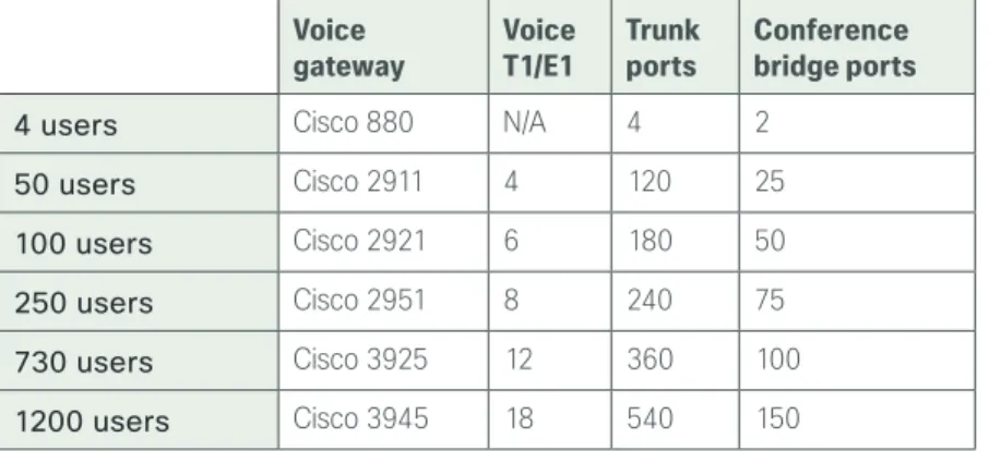
The sizing information in this guide supersedes the information from the various CVD WAN design guides because the number of SRST users determines the proper router model, as listed in the following table.
Table 1 - Standalone voice gateway scaling options Voice
gateway Voice T1/E1 Trunk ports Conference bridge ports
4 users Cisco 880 N/A 4 2
50 users Cisco 2911 4 120 25
100 users Cisco 2921 6 180 50
250 users Cisco 2951 8 240 75
730 users Cisco 3925 12 360 100
1200 users Cisco 3945 18 540 150
Cisco Unified Communications
The products and priorities for this design were based on requirements from customers, partners, and Cisco field personnel. Your specific business requirements may be different from those in this guide, in which case, the product selection may not exactly match your needs. Please contact an authorized Cisco partner or representative to validate any design changes that you plan to deploy.
Cisco Unified Communications has the following software components:
• Cisco Unified CM provides the Internet Protocol private branch exchange (IP PBX) functionality for all users within the headquarters site as well as the remote sites. The first Unified CM appliance is known as the publisher because it contains the master database to which all other Unified CM appliances within the same cluster subscribe. The rest of the appliances are known as either subscribers or Trivial File Transfer Protocol (TFTP) servers, based on their function in the cluster.
• Cisco Unity Connection provides services such as voicemail, voicemail integration with your email inbox, and many other productivity features. Voicemail is considered part of the unified communications foundation.
The following cluster design option is used in this guide:
• A 1:1 publisher subscriber redundancy in Cisco Unified CM configurations.
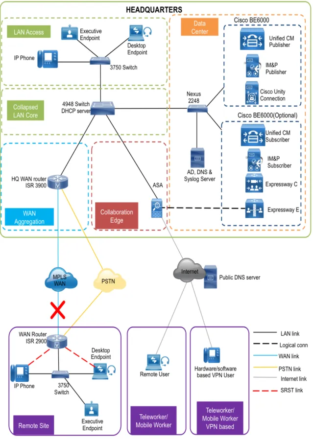
Single Cluster Centralized Design
The following single cluster centralized design model provides a highly available and scalable call-control and voicemail system capable of email client integration.
The Cisco Business Edition (BE) 6000 uses a single Cisco UCS server platform for up to 1000 users. The virtualized server provides the following:
• The publisher, subscriber and TFTP functions are combined with Cisco Unity Connection on a single hardware platform in order to help lower the capital and operational expenses.
• The Cisco UCS C220 M3 hardware platform for the Cisco BE 6000 is a 1 rack unit form factor. • The Cisco Business Edition 6000 supports Cisco Unified Presence and Cisco Unified Contact Center
Express on the same virtual server platform. You can also add a redundant server to this configuration if an organization requires it.
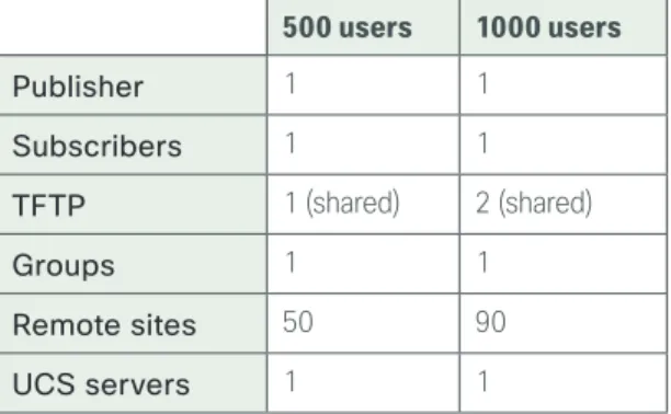
Table 2 - Cisco Unified Communications Manager centralized design model 500 users 1000 users
Publisher 1 1
Subscribers 1 1
TFTP 1 (shared) 2 (shared)
Groups 1 1
Remote sites 50 90
UCS servers 1 1
For the design model, the following features are provided:
• Connect each server to a different switch within the server room or data center in order to provide for high availability should a switch or link connection fail.
• There is sufficient capacity for multiple devices for each user. For example, you can enable a desk phone and a soft phone with enough computer telephony integration to allow a high percentage of users to have click-to-call or other applications that can remotely control their phones.
• There is additional capacity available for phones that are not assigned to a specific user, such as those in public areas, meeting rooms, storage areas, and break rooms.
• Cisco Unity Connection is deployed as a simple voicemail system. However, with additional
configuration, it will provide calendar-based call-handling integration with Microsoft Exchange, Cisco Unified MeetingPlace, and other networkable voicemail systems. Cisco Unity Connection is deployed in the architecture as non-redundant, although a second high-availability server can be added, if required. • It is possible to support other services, including advanced conferencing, contact center, and video
conferencing. These advanced services require additional hardware and software, and they are not covered in this document.
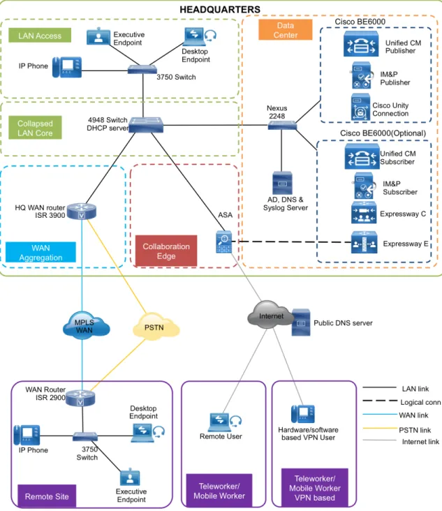
Figure 1 - Cisco Unified CM, Cisco Unity Connection, and IM and Presence
The centralized design consists of a headquarters site and up to 90 remote sites. The Cisco Unified CM and the Cisco Unity Connection server instances are placed at the main site to handle the call processing for up to 1000 telephony users with voice messaging. Optional Cisco BE 6000 server can be placed at the main site for redundancy and to install other applications. Each remote site takes advantage of the Cisco ISR G2 router that was deployed as part of the WAN deployment. Remote worker/mobile worker use cases leveraging Cisco Expressway C & Expressway E are discussed in detail in Collab Edge using Cisco BE 6000 Design Guide.
Auto-Registration
Auto-registration allows Cisco Unified CM to automatically assign a directory number to new phones as they are deployed in your network. With Cisco Unified Configurator for Collaboration (CUCC), auto-registration is enabled in order to allow for quick and easy deployment of phones. After the phones are registered and the guide has been followed completely, users configured in the system should use Cisco Extension Mobility to log into the auto-registered phones to enable off-net dialing.
By default, auto-registered phones are able to dial on-net directory numbers as well as off-net emergency 911 calls. They are not, however, able to dial off-net numbers.
Leaving auto-registration enabled carries a security risk in that “rogue” phones can automatically register with Cisco Unified CM. You should only allow auto-registration for brief periods when you want to perform bulk phone adds during phone deployment.
Tech Tip
Active Directory Integration
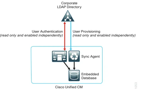
Active Directory integration allows you to provision users automatically from the corporate directory into the Cisco Unified CM database, which makes it possible to maintain a single directory as opposed to separate directories. Therefore, you don’t have to add, remove, or modify core user information manually in Unified CM each time a change occurs in the corporate directory. The other advantage is that end users are able to authenticate to Unified CM and Cisco Unity Connection by using the same credentials in Active Directory, which reduces the number of passwords across the network.
Figure 2 - Directory integration with Cisco Unified CM
1053
User Authentication
(read only and enabled independently) User Provisioning(read only and enabled independently)
Cisco Unified CM Corporate LDAP Directory
Sync Agent
Embedded Database
Dial Plan
The dial plan is one of the key elements of an IP telephony system and an integral part of all call-processing agents. Generally, the dial plan is responsible for instructing the call-processing agent on how to route calls. CUCC configures a North American Numbering Plan (NANP) dial plan as part of the path selection for PSTN destinations. You can modify the dial plan to meet your specific needs, but CUCC has the options to configure the NANP with 7-digit or 10-digit local dialing. The following two sets of patterns can be selected.
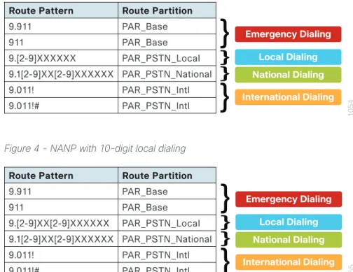
Figure 3 - NANP with 7-digit local dialing
1054
Route Pattern Route Partition
9.911 PAR_Base 911 PAR_Base 9.[2-9]XXXXXX PAR_PSTN_Local 9.1[2-9]XX[2-9]XXXXXX PAR_PSTN_National 9.011! PAR_PSTN_Intl 9.011!# PAR_PSTN_Intl Emergency Dialing Local Dialing National Dialing International Dialing
Figure 4 - NANP with 10-digit local dialing
1055
Emergency Dialing Local Dialing National Dialing International Dialing Route Pattern Route Partition
9.911 PAR_Base 911 PAR_Base 9.[2-9]XX[2-9]XXXXXX PAR_PSTN_Local 9.1[2-9]XX[2-9]XXXXXX PAR_PSTN_National 9.011! PAR_PSTN_Intl 9.011!# PAR_PSTN_Intl
There are two configured international route patterns: one to route the variable-length dialed digits and one configured with a pound (octothorpe) in order to allow users to bypass the inter-digit timeout. The 911 and 9.911emergency route patterns are created with urgent priority to prevent inter-digit timeout delays when they are entered from a phone.
Site Codes
It is recommended that you use a uniform on-net dial plan containing an access code, a site code, and a 4-digit extension. The use of access and site codes enables the on-net dial plan to differentiate between extensions at remote sites that could otherwise overlap with each other.
When you use this method, a phone in San Jose, CA can have the same 4-digit extension as one in Houston, TX without creating a numbering conflict. For example: 408-555-1234 in San Jose and 713-555-1234 in Houston. For networks with 90 sites or less, the dial plan consists of the following:
• One digit as an inter-site access code
• Two digits for the site code to accommodate up to 90 sites • Four digits for the site extension
CUCC requires a format of 8 + SS + XXXX, where 8 is the on-net access code, SS is a 2-digit site code of 10-99, and XXXX is a 4-digit extension number, giving a total of seven digits.
Figure 5 - Two-digit site code format
1056
2-Digit Site Code
Access Code + Site Code + Extension 8 1 0 1 2 3 4
Access Code Extension
Class of Service
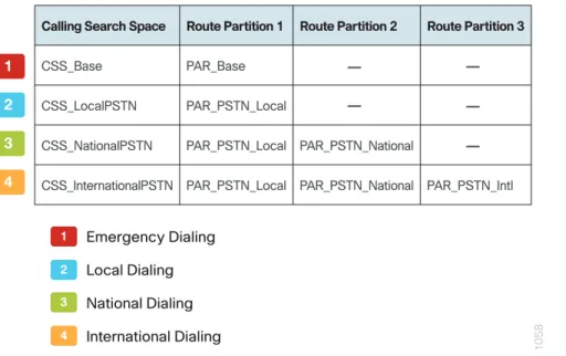
Class of service is configured in Cisco Unified CM by using calling search spaces and partitions. There are four classes of service, and they provide PSTN access for emergency, local, national, and international dialing.
Figure 6 - Calling search spaces and partitions
1058
1 2 3 4
Calling Search Space Route Partition 1 Route Partition 2 Route Partition 3
CSS_Base PAR_Base
CSS_LocalPSTN PAR_PSTN_Local
CSS_NationalPSTN PAR_PSTN_Local PAR_PSTN_National
CSS_InternationalPSTN PAR_PSTN_Local PAR_PSTN_National PAR_PSTN_Intl 1 2 3 4 Emergency Dialing Local Dialing National Dialing International Dialing — — — — —
With CUCC, devices are auto-registered with the CSS_Base calling search space. This allows all devices to dial both on-net and emergency off-net numbers.
The remaining calling search spaces are configured on the user device profile directory number and provide local 7-digit or local 10-digit, national, and international dialing capabilities.
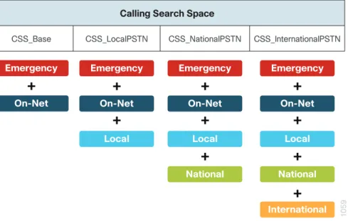
Figure 7 - Calling capabilities for calling search spaces
1059
International Calling Search Space
CSS_Base CSS_LocalPSTN CSS_NationalPSTN CSS_InternationalPSTN Emergency On-Net Local National
+
+
+
+
Emergency On-Net Local National+
+
+
Emergency On-Net Local+
+
Emergency On-Net+
For example, if a user requires international dialing capability, their directory number would be assigned the CSS_InternationalPSTN calling search space, which includes dialing accessibility to all PSTN route patterns as well as national, local, emergency, and on-net numbers.
This CVD is considering 8+ 6-digit dial plan for this deployment, which is based on NANP dial plan principles. In case there is a need for +E.164 dial plan for your deployment, please refer to Collaboration Solution Reference Network Design (SRND) Dial Plan chapter
Tech Tip
Local Route Groups
The Local Route Group feature in Cisco Unified CM decouples the PSTN gateway physical location from the route patterns and route lists that are used to access the gateway. The feature assigns a local route group to each route group, based on the device pool setting of the originating device. Therefore, phones and other devices from different locations can use a single set of route patterns, but Unified CM selects the correct gateway to route the call.
CUCC assigns a unique route group to a device pool so each site can choose the correct SIP gateway. The route group is associated with the device pool by using the local route group setting. This simplifies the process of provisioning by allowing the administrator to create a single set of route patterns for all sites. When a call is made from a device that matches the route pattern, Cisco Unified CM uses the Local Route Group device pool setting to determine the proper route group, which selects the SIP gateway assigned to the site.
Figure 8 - Cisco Unified CM call routing 1060 CSS_Base 9.[2-9]XXXXXX Local Internal 911
All IP Phones 9.1[2-9]XX
[2-9]XXXXXX
National
9.011!# 9.011!
International
Local National International
Local Route Group Device Pool Route List
Site 1 Gateway Site 2 Gateway
Lines assigned additional classes of service All phones assigned
the CSS_Base calling search space
HQ Gateway Route List s Route Group s D evic es Calling Se arch Sp ac es (C SS ) PSTN PSTN PSTN 9.911 Par titions (C ontaining Route Pa tterns)
Survivable Remote Site Telephony
In a centralized design, when IP phones lose connectivity to Cisco Unified CM because the application is unreachable, IP phones in remote-site offices or teleworker homes lose call-processing capabilities. The Survivable Remote Site Telephony (SRST) feature provides basic IP telephony backup services because IP phones fall back to the local router at the remote site when connectivity is lost. IP phones continue to make calls within the site and out the local gateway to the PSTN.
At a remote site with more than one PSTN gateway, configure SRST on the router with the most voice ports. If only one router has PSTN interfaces, SRST must be configured on the router to reduce complications.
Using the Cisco 2921 ISR router, a maximum of 100 phones are supported at a remote site. If you have more phones than a single SRST router can manage, you should consider using the higher end ISR router 3945. Phones can use SCCP or SIP to register with the SRST process on the remote-site router. Different commands are needed for each type of phone, and the commands can be configured together or individually on each router within the organization.
The following diagram shows SRST providing service to phones at a remote site when the WAN is down.
When a remote site falls back to SRST and site codes are in use, voice translation commands are required in the router to maintain 4-digit local dialing. The commands are explained in more detail in the deployment section of this guide.
Device Mobility
CUCC uses a feature called device mobility that allows Cisco Unified CM to determine if the IP phone is at its home or a roaming location. Unified CM uses the device’s IP subnet to determine the physical location of the IP phone. By enabling device mobility within a cluster, mobile users can roam from one site to another, thus acquiring the site-specific settings. Unified CM then uses these dynamically allocated settings for call routing, codec selection, media resource selection, and Unified CM groups.
This feature is used primarily to reduce the configuration on the devices themselves by allowing configuration of many parameters at the site level. These parameters are dynamically applied based on the subnet to which the device is attached. This allows for a fast and reliable deployment because the administrator does not have to configure each phone individually or ensure the phone is at the correct location.
Extension Mobility
CUCC uses the Extension Mobility feature, enabling end users to personalize a Cisco Unified IP Phone, either temporarily or permanently, based on business requirements. The Extension Mobility feature dynamically configures a phone according to the authenticated user’s device profile. Users log into an IP phone with their username and PIN, and their device profile is uploaded to the IP phone. Extension Mobility alleviates the need for device-to-user association during provisioning. This saves deployment time while simultaneously allowing the user to log into any phone within the organization, allowing phone-sharing capabilities.
Extension Mobility can be enabled in such a way that it allows users to log into IP phones but does not allow them to log out. With this method, Extension Mobility is exclusively designed for IP phone deployment, but not as an ongoing feature in the organization. By default, the CUCC configuration allows users to log out of the IP phone, which enables Extension Mobility for both IP phone deployment and user feature functionality.
The user-provisioning capabilities of this guide require an IP phone that supports services to allow the use of Extension Mobility. All users imported with CUCC will have a default PIN of 112233
Tech Tip
Extend and Connect
Extend and Connect enables users to leverage the benefits of UC applications from any location using any device. It allows administrators to deploy computer telephony integrations applications which interoperate with any endpoint. Configuring Extend and Connect section of this document covers the detailed steps to configure Extend and Connect and use Jabber for Extend and Connect.
Media Resources
Media resources have been provisioned as part of the procedure for every site in order to ensure that remote sites use their local conference bridges and avoid unnecessary voice traffic over the WAN. The naming of the conference bridges needs to match those provisioned by CUCC. The names are always CFB1<Site Name> and CFB2<Site name>, if there are two. For example, if the headquarters site is HQ1, the conference bridge names are CFB1HQ1 and CFB2HQ1.
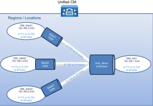
Call Admission Control
The default design is a hub-and-spoke topology in which each remote site is connected to the headquarters site over a bandwidth-constrained WAN. The CUCC design uses regions and locations to define locations-based Call Admission Control. For calls within a site, the regions are configured for the G.722 or G.711 codec running at 80 kbps, and there are no limits to the number of calls allowed within a site. For calls between the sites, the regions are configured for the G.729 codec running at 24 kbps. The size of the site determines the CUCC default voice bandwidth setting for inter-site calls. For sites with only 500 users, the default setting is two inter-site calls (48 kbps). The amount of bandwidth in and out of each site can be modified within CUCC, if the defaults do not match the provisioned WAN bandwidth.
By default, Call Admission Control is not calculated for calls to and from the central site (headquarters). It’s expected that as long as the spokes are provisioned for Call Admission Control, the hub will not be oversubscribed on a traditional WAN. This is the case for all hub-and-spoke topologies; however, for a Multiprotocol Label Switching (MPLS)–based network, which is considered a hub-less hub and spoke, you will need to modify the headquarters site default bandwidth within CUCC to provide the correct Call Admission Control based on the speed of the link.
Figure 10 - Hub-and-spoke topology for Call Admission Control
Point-to-Point Video
CUCC can be used to deploy the video endpoint, which would enable point-to-point video between two participants. Desktop Video endpoints such as EX60, EX90 and DX650 can be deployed using CUCC.
IM and Presence
Cisco Jabber for Windows streamlines communications and enhances productivity by unifying presence, instant messaging, video, voice, voice messaging, desktop sharing, and conferencing capabilities securely into one desktop client. It offers flexible deployment models and integrates with commonly used applications. Cisco Jabber for Windows can also be deployed in virtual environments. In a virtual environment, it supports presence, instant messaging, and desk-phone control.
Cisco Jabber can be deployed on-premises or by using a cloud-based service, offering IT departments the flexibility to choose the model that best suits their business.
The on-premises Jabber solution includes the following components: • Unified CM IM and presence, for instant messaging and presence
• Unified CM, for audio and video call management, user and device configuration, and Jabber software phone and directory synchronization
• Cisco Unity Connection, for voice mail
• Jabber for Windows, Jabber for iPad, and Jabber for iPhone • MS Active Directory, for client user information
• WebEx Meeting Center, for hosted meetings
• Network Time Protocol (NTP) server, for logging consistency • Domain Name System (DNS) server, for name-to-IP resolution • Syslog server, for logging events (optional)
This guide describes the following Cisco Jabber features:
• Communication integration—Use a single, intuitive interface for instant messaging with individuals and groups, IP telephony, visual voicemail, voice and web conferencing, desktop sharing, communication history, and integrated directories.
• Presence—View real-time availability of co-workers and colleagues within and outside the enterprise network.
• Enterprise instant messaging—Chat in real time by using instant messaging. Several chat modes are supported, ranging from:
◦ Point-to-point chat with co-workers inside your network, or supported federated business and personal contacts
◦ Group chat, which enables multiple colleagues to communicate and collaborate in a single discussion
◦ Personal instant messaging history for your reference
• Predictive search—Provides suggestions to you as you type in a search query and is capable of indexing your Cisco Jabber contact list, recent contacts, Microsoft Active Directory, or LDAP directory.
◦ Media escalation—Escalate from a chat to an audio call, video call, desktop share, or web meeting. Media escalations are as easy as clicking a button.
◦ Desktop share—Share what is on your desktop with Cisco Jabber users, as well as Cisco and other standards-based video endpoints.
◦ Integrated voice and video telephony—A coordinated video display on the screen and voice conversation with a dedicated soft phone.
You can make, receive, and control your phone calls whether you are in or out of the office and support business-quality video communication up to high-definition (720p) and high-fidelity wideband audio. You can also use voice, video, and even desktop share when interacting with TelePresence endpoints and room-based and multipoint videoconferencing systems.
Many call-control options are available, including mute, call transfer, call forwarding, and ad-hoc conferencing. The reliability and failover features of Cisco Unified Communications Manager are supported.
• Visual voice message access—Access and manage your voice messages.
◦ View, play back, and delete voice messages from Cisco Unity Connection.
CUCC Directories and Filenames
The Cisco Unified Configurator for Collaboration (CUCC) tool is available in a Windows and Mac version. The different versions can be downloaded from the following URLs:
• Windows: http:// www.cisco.com/go/cvd/collaboration • Mac: http:// www.cisco.com/go/cvd/collaboration
• CUCC has several directories and key filenames that are referenced throughout this guide. The following table lists the directories and filenames.
Table 3 - CUCC directories and filenames
Type Path or filename Description
Default .\ Default directory
.\CUCC.exe or CUCC.app CUCC application
.\Sample User.csv Sample csv file for New Users and Device Profiles
.\Readme.txt This table
Log .\log System log directory
.\log\ccts.log General log for all areas .\log\new_server.log New Server and Site log .\log\export_gateway.log Gateway Template log
.\log\new_user.log New Users and Device Profiles log .\log\modify_server.log Modify Server and Site log
.\log\modify_user.log Modify Users and Device Profiles log .\log\phone.log Phone Deployment log
Summary .\Overview Summary overview directory for data used in Server and Site
Output .\packet Output packet directory
.\packet\gateway Output text files for Gateway Templates formatted as follows: SIP_Site_Name_GWY.txt
.\packet\saveAllData Output tar file for Saved Entered Data
.\packet\server Output tar files for Server and Site formatted as follows: Server_YYYYMMDDhhmm.tar
.\packet\user Output tar files for Users and Device Profiles formatted as follows: User_YYYYMMDDhhmm.tar
Input .\template Input template directory
.\template\dialplan Input csv files for Dial Plan
.\template\user Input csv and xml files for Users and Device Profiles .\template\gateway Input xml file for Gateway Templates
.\template\Server Input tar file for base Unified CM configuration .\template\site Input csv sample files for Site Information
.\template\temp Input csv files extracted from base Unified CM tar file .\template\udp Input xml files for Device Profiles
Deployment Details
This guide uses CUCC to install, configure, and deploy basic telephony and simple voice messaging. This turnkey solution is easy and quick. It also provides a solid foundation for further configuration and deployment of advanced unified communications features, without the need to redesign or reengineer when a new element or service is added.
The first process presents detailed procedures for preparing your network for IP phones and provides a section on how to choose the correct Cisco Unified IP Phones for your organization.
Preparing the Network for IP Phones
1. Enable DHCP option 150
P
RO
C
ES
S
The campus design is voice-ready because it includes the QoS settings, VLANs, and IP subnets needed for voice endpoints. It also includes the Dynamic Host Configuration Protocol (DHCP) scopes for the voice VLANs. However, the DHCP option that automatically assigns the call-control agent to the voice endpoints is covered in this module because it is specific to the Cisco Unified Communications solution.
Procedure 1 Enable DHCP option 150
DHCP is used to obtain an IP address, subnet mask, default gateway, domain name, DNS addresses, and TFTP server information. When you are configuring DHCP for use in a Cisco Unified CM deployment, this design recommends a localized server or Cisco IOS device to provide DHCP service at each site. This type of deployment ensures that DHCP services are available to remote-site telephony devices during WAN failures. DHCP option 150 provides the IP addresses of the TFTP servers, which allows the phones to download their configuration files and firmware. This option is added to the voice scopes for wired and wireless networks. Option 150 allows up to two IP addresses to be returned to phones as part of the DHCP scope.
The phone always tries the first address in the list, and it only tries the subsequent address if it cannot establish communications with the first TFTP server. The second address provides a redundancy mechanism that enables phones to obtain TFTP services from another server if their primary TFTP server is unreachable. However, it does not provide dynamic load balancing between the two servers. This design recommends that you configure different ordered address lists of TFTP servers in the DHCP scopes to allow for manual load balancing.
For example:
• In subnet 192.168.2.0/24, option 150: CUCM-Pub (primary), CUCM-Sub (secondary) • In subnet 192.168.5.0/24, option 150: CUCM-Sub (secondary), CUCM-Pub (primary)
Under normal operations, a phone in subnet 192.168.2.0/24 will request TFTP services from CUCM-Pub, while a phone in subnet 192.168.5.0/24 will use CUCM-Sub. If CUCM-Pub fails, then phones from both subnets will request TFTP services from CUCM-Sub. The method for load sharing between the DHCP scopes is left up to the network administrator, because they will have the best knowledge of how many phones reside in each subnet.
If the remote site has a single WAN router without a distribution layer, the best place for DHCP is on the router. If the remote site has dual WAN routers or a distribution layer, the DHCP service should be located on a standalone server or on a distribution switch.
In all situations, phones need option 150 added to their DHCP scope configurations. If the headquarters site uses the primary TFTP server as the first choice, the remote sites should use the secondary TFTP as the first choice until the phone count is balanced between the two servers.
If you are using a Microsoft DHCP server, complete Option 1 of this procedure. If you are using the Cisco IOS DHCP server feature, complete Option 2.
Option 1: Enable option 150 on Microsoft DHCP server
Use the following commands in order to enable option 150 on a Microsoft DHCP server. Step 1: From the Microsoft server, open the DHCP Server Administration Tool.
Step 2: On the left side of the page, navigate to[active directory name] > IPv4 (Example: ad.cisco.local > IPv4). Step 3: Right-click IPv4, and then choose Set Predefined Options from the list.
Step 4: Click Add, enter the following information, and then click OK: • Name—TFTP Servers
• Data Type—IP Address
• Array—Select the check box. • Code—150
Step 5: Click Edit Array, add up to two IP addresses for your TFTP servers, and then click OK.
Step 6: On the Predefined Options and Value page, verify the information, and then click OK.
Option 2: Enable option 150 using Cisco IOS DHCP server feature
Use the following commands in order to enable option 150 in the appropriate DHCP pools in Cisco IOS devices. Step 1: Log in to the device with a username that has the ability to make configuration changes.
Step 2: In the global configuration section, edit the DHCP pools supporting IP phones to include option 150 so the phones can find the TFTP servers at 192.168.1.17 (secondary) and 192.168.1.16 (primary).
ip dhcp pool wired-voice
network 192.168.5.0 255.255.255.0 default-router 192.168.5.1
dns-server 192.168.1.10
option 150 ip 192.168.1.17 192.168.1.16 domain-name cisco.local
ip dhcp pool wired-voice2
network 192.168.2.0 255.255.255.0 default-router 192.168.2.1 dns-server 192.168.1.10
option 150 ip 192.168.1.17 192.168.1.16 domain-name cisco.local
Phone Models
For decades, traditional phone systems have provided basic dial tone and voicemail services, but there is little they can offer in terms of advanced communication features. Organizations who lead the way in technological innovation expect the next generation of handsets to provide features that will transform the way they operate their business. Even as they lead the way with new tools and technology, they want to cut costs by eliminating expensive wiring to every desktop and lowering electricity usage. The high cost of energy and the push for a greener planet is causing organizations to rethink every aspect of their business to see if they can lower their carbon footprint.
At the other end of the spectrum, cost-conscious organizations want to lower costs by saving money in nonessential areas of their business. Most employees only need a simple telephone handset. Even a character-based display screen is too expensive for their budgets. Aging phones systems have been discontinued, and spare parts are getting harder to find. These challenges are causing organizations to search for a cost-effective solution to their telephony needs.
Several new Cisco Unified IP Phones have been introduced over the last few years to address the high-end and cost-conscious business models. Cisco Unified IP Phones 9951 and 9971 support video telephony by adding a USB camera to a high-end color phone. This allows customers to meet face-to-face with others in their organization by using the simple interface of a telephone. The color screens are larger with higher resolution than other models, and they support more tilt options to allow better viewing of the video images. They support Bluetooth and USB to give the end user more flexibility when choosing headsets. Cisco Unified IP Phone 9971 supports Wi-Fi connectivity, which frees users from the constraints of a hardwired telephone infrastructure within their buildings. Cisco Unified IP Phone 8945 also supports video telephony with a built-in camera and a high-resolution color display. Cisco Unified IP Phone 8900 Series and 9900 Series have a deep-sleep power-save option, which can reduce power consumption by up to 90 percent compared to the normal operation of the phone. This design recommends Unified IP Phone 8945 for a four-line video phone and Unified IP Phone 9971 for a five-line, video, and Wi-Fi–enabled phone.
Cisco Unified IP Phone 7800 Series is a high-fidelity voice communications portfolio designed for people- centric collaboration. It combines always-on reliability and security, full-featured easy-to-use IP telephony, and wideband audio to increase productivity, with an earth-friendly design for reduced costs. These basic phone models provide essential calling functionality and still maintain the inherent flexibility of an IP-based endpoint, which operates from an existing Ethernet port for power and connectivity. The Cisco IP Phone 7800 Series brings a higher quality standard, with full wideband audio support for handset, headset and speaker, to our voice-centric portfolio. A new ergonomic design includes support for larger grayscale, graphical backlit displays. Cisco Unified IP Phone 7821 is a two-line, endpoint that is designed for information workers and managers. The Cisco IP phone 7841 is a four-line endpoint that is designed for information workers, the administrative staff and managers who have moderate level of voice communication needs. The Cisco IP phone 7861 has 16 lines and is ideal for the users such as administrative staff, managers and agents in contact centers.
Cisco Unified Wireless IP Phone 7925 is recommended for mobility, Cisco Unified IP Conference Station 7937 is recommended for conference rooms, and the Cisco IP Communicator software client is recommended to provide a desktop computer solution.
The phones take full advantage of the Cisco recommended QoS settings by using Class Selector 3 (CS3) for signaling, Assured Forwarding 41 (AF41) for video, and Expedited Forwarding (EF) for voice. These settings are recommended for Cisco Medianet because they provide optimum voice and video quality while maintaining the integrity of the data flows within the network. The phones can also use SRST at the remote sites in order to provide survivability in the case of a WAN outage.
Cisco Unified IP Phone 7900 Series are also available as an alternative for users who do not need the high-end features of the Unified IP Phone 8900 and 9900 Series phones, but require more functionality than what is found in the Unified IP Phone 7800 Series models.
Network Preparation Summary
To ensure that your phones are registered at the correct time, you need to deploy DHCP option 150 and select your IP phone models before you perform the deployment procedures found in the next process.
Preparing the Platform for Cisco Unified CM
1. Configure platform connectivity to the LAN 2. Prepare the server for Unified CM
P
RO
C
ES
S
For a quick and easy installation experience, it is essential to know up front what information you will need. To install Cisco Unified CM, make sure you have completed the following steps before you start:
• Download the Open Virtual Archive (OVA) file from the Cisco website at:
http://software.cisco.com/download/release.html?mdfid=284603137&flowid=47762&softwareid=283088 407&release=10.0%281%29&relind=AVAILABLE&rellifecycle=&reltype=latest
For an installation using ESXi 4.1, choose the latest OVA file with vmv7 in the name. For example: cucm_10.0_vmv7_v1.7.ova
For an installation using ESXi 5.0 or higher, choose the latest OVA file with vmv8 in the name. For example: cucm_10.0_vmv8_v1.7.ova
• Check the Cisco website to determine if there is a patch for your version of Cisco Unified CM:
http://software.cisco.com/download/release.html?mdfid=284603137&flowid=47762&softwareid=2820742 95&release=10.0%281%29&relind=AVAILABLE&rellifecycle=&reltype=latest
Procedure 1 Configure platform connectivity to the LAN
The Cisco Unified CM server can be connected to a Cisco Nexus switch in the data center or a Cisco Catalyst switch in the server room. Please choose the option that is appropriate for your environment.
Option 1: Connect the Cisco Unified CM server to a Cisco Nexus 2248UP switch
Step 1: Log in to the Cisco Nexus switch with a username that has the ability to make configuration changes. Step 2: If there is a previous configuration on the switch port where the Cisco Unified CM server is connected, remove the individual commands by issuing a no in front of each one. This brings the port back to its default state.
Step 3: Configure the port as an access port. interface Ethernet1/1/4
description Unified CM switchport access vlan 148
Option 2: Connect the Cisco Unified CM server to a Cisco Catalyst 3750-X Series
switch
Step 1: Log in to the Cisco Catalyst switch with a username that has the ability to make configuration changes. Step 2: Clear the interface’s configuration on the switch port where the Cisco Unified CM server is connected.
default interface GigabitEthernet1/0/6
Step 3: Configure the port as an access port. interface GigabitEthernet1/0/6
description Unified CM switchport access vlan 148
Procedure 2 Prepare the server for Unified CM
Follow the steps below to deploy an OVA file in order to define the virtual machine requirements.
Step 1: Open VMware vSphere Client, click the server hardware you want to use for this install, and then navigate to File > Deploy OVF Template.
Step 2: In the Deploy OVF Template wizard, enter the following information:
• On the Source page, click Browse, select the Cisco Unified CM OVA file downloaded from Cisco or from the datastore of the Cisco BE 6000 server, click Open, and then click Next.
• On the OVF Template Details page, verify the version information, and then click Next:
• On the Name and Location page, in the Name box, enter the virtual machine name CUCM-Pub. In the Inventory Location tree, select the location to deploy the server, and then click Next.
• On the Deployment Configuration page, in the Configuration list, choose the following node, and then click Next.
◦ 1000-user node (BE6K)—for a cluster of 1000 or fewer users.
• On the Disk Format page, choose Thick Provision Eager Zeroed, and then click Next. • On the Ready to Complete page, verify the settings, and then click Finish.
Step 4: After the virtual machine is created, click on the server name (Example: CUCM-Pub), navigate to the Getting Started tab, and then click Edit virtual machine settings.
Step 5: On the Hardware tab, select CD/DVD Drive 1, and then select Connect at power on.
Step 6: Select Datastore ISO File, click Browse, navigate to the location of the Cisco Unified CM bootable installation file (or browse the datastore to find the CUCM installation file), select the correct ISO image, and then click OK.
Step 7: On the Getting Started tab, click Power on virtual machine. Step 8: Click the Console tab, and then watch the server boot. After the ISO loads, the virtual machine is prepared for installation.
Installing Cisco Unified CM
1. Install the first Cisco Unified CM platform 2. Install licenses and start services
3. Configure additional servers 4. Install the redundant server 5. Start services
P
RO
C
ES
S
The following information is needed for the installation: • Time zone for the server
• Host name, IP address, network mask, and default gateway • Domain Name System (DNS) server IP addresses
• Administrator ID and password
• Organization, unit, location, state, and country • Network Time Protocol (NTP) server IP addresses • Security password
• Application username and password
• Lightweight Directory Access Protocol (LDAP) information for integration with Microsoft’s Active Directory:
◦ Manager Distinguished Name (read access required)
◦ User Search Base
◦ Host name or IP address and port number for the LDAP server
When users are created in Active Directory, either the telephone number or the IP phone attribute is mandatory. Otherwise, the users cannot be imported into Cisco Unity Connection.
Complete the tasks listed below before you start the installation: • In DNS, configure Cisco Unified CM host names • Obtain license files from the Cisco licensing system
• On the PC or Mac used for administration, install an archive program for opening .tar files
For standard deployments, this design recommends that you configure Cisco Unified CM to use IP addresses rather than host names. However, during the initial installation of the publisher node in a Unified CM cluster, the publisher is referenced in the server table by the host name you provided for the system. When new subscribers are added to a publisher, the initial use of host names makes it easier to identify the servers for troubleshooting purposes. The host names will be changed to IP addresses later in this guide.
Each subscriber should be added to this server table one device at a time, and there should be no definitions for non-existent subscribers at any time, other than for the new subscribers being installed.
Procedure 1 Install the first Cisco Unified CM platform
This procedure is for installing the first Cisco Unified CM platform. If this is not the first Unified CM platform, skip ahead to Procedure 6, “Install the redundant server.”
After the ISO/DVD loads, continue the installation on the server console. Step 1: On the DVD Found page, choose OK.
Step 2: If the media check passes, choose OK.
If the media check does not pass, contact Cisco Technical Assistance Center or your local representative in order to replace the media, and then repeat Step 1.
Step 3: On the Product Deployment Selection page, choose Cisco Unified Communications Manager, and then choose OK
Step 4: On the Proceed with Install page, verify that the version is correct, and then choose Yes. Step 5: On the Platform Installation Wizard page, choose Proceed.
Step 7: If the Import Windows Data page is displayed, choose No. Step 8: On the Basic Install page, choose Continue.
Step 9: On the Timezone Configuration page, use the arrow keys to select the correct time zone, and then choose OK.
Step 10: On the Auto Negotiation Configuration page, choose Continue. Step 11: On the MTU Configuration page, choose No.
Step 12: On the DHCP Configuration page, choose No.
Step 13: On the Static Network Configuration page, enter the following information, and then choose OK: • Host Name—CUCM-Pub first node (publisher)
• IP Address—192.168.1.16
• IP Mask—255.255.255.0
• GW Address—192.168.1.1
During the software installation, the server performs a reverse DNS lookup on the name and IP address entered above. The installation halts if the lookup does not succeed, so please verify your server information is properly entered into DNS and the associated pointer records are created beforehand.
Tech Tip
Step 15: Enter the following information, and then choose OK: • Primary DNS—192.168.1.10
• Domain—cisco.local
Step 16: On the Administrator Login Configuration page, enter the following information, and then choose OK: • Administrator ID—Admin
• Password—[password]
• Confirm Password—[password]
The password must start with an alphabetic character and have at least six characters, and it can contain alphanumeric characters, hyphens, or underscores.
Tech Tip
Step 17: On the Certificate Information page, enter the details that will be used to generate the certificate used for secure communications, and then choose OK.
Step 19: On the Network Time Protocol Client Configuration page, next to the NTP Server 1 prompt, enter 192.168.1.10, add up to four more NTP host names or IP addresses, and then choose OK.
Step 20: On the Security Configuration page, enter a security password, confirm the password, and then choose OK.
You use the security password during the remaining nodes installation process. Step 21: On the SMTP Host Configuration page, choose No.
Step 22: On the Smart Call Home Enable Page, choose Disable all Call Home on System Start.
Smart Call Home offers proactive diagnostics and real time alerts on click Cisco devices, which provides higher network availability and increased operational efficiency. Smart Call Home is a secure connected service of Cisco Unified
Communications Essential Operate Services ESW for the Cisco Unified Communication Manager. To enable Smart Call home feature, please refer the document available at cisco.com
Tech Tip
Step 23: On the Application User Configuration page, enter the following information, and then choose OK: • Application User Username—CUCMAdmin
• Application User Password—[password]
• Confirm Application User Password—[password]
Step 24: On the Platform Configuration Confirmation page, choose OK.
The system finishes the rest of the installation process without user input. The system reboots a few times during installation. The process can take 60 minutes or more, depending on your server hardware.
After the software has finished installing, the login prompt appears on the console.
Step 25: In vSphere Client, navigate to the virtual machine’s Getting Started tab, and then click Edit virtual machine settings.
Step 26: On the Hardware tab, select CD/DVD Drive 1. Step 27: Clear Connect at power on, and then click OK.
Procedure 2 Install licenses and start services
After the first Unified CM platform is installed, there are several configuration steps that have to be completed in order to prepare the publisher for the remaining servers.
Step 1: In a web browser, access the IP address or hostname of the publisher, and then in the center of the page, under Installed Applications, click Cisco Prime License Manager.
Step 2: On the login page, enter the following application username and password from Step 23, and then click Login:
• User Name—CUCMAdmin (case-sensitive) • Password—[password]
Step 3: Navigate to Inventory > Product Instances, and then click Add.
The username and password for adding the product instances is the case-sensitive platform administrator ID that was created when installing the server software.
Tech Tip
Step 4: Enter the following information for Cisco Unified CM, and then click Test Connection: • Name—CUCM-Pub
• Description—CUCM Publisher
• Product Type—Unified CM
• Hostname/IP Address—192.168.1.16 (publisher)
• Username—Admin (case-sensitive platform administrator ID from Step 16) • Password—[password]
Step 5: In the message window, click OK. Step 6: If the connection is successful, click OK.
If the connection is not successful, repeat Step 4 through Step 6 with the correct information. Step 7: Click Synchronize Now.
Step 8: Navigate to Licenses > Fulfillment, and then select Other Fulfillment Options > Fulfill Licenses from File.
Extract the .bin file from the .zip before trying to install the license in the next step. The installation process returns an error if you try to install the .zip file.
Tech Tip
Step 9: On the Install License File page, click Browse, locate the directory that contains the license files you obtained prior to installation, select the .bin file, click Open, and then click Install. A message confirms that the license was successfully installed.
Step 10: Repeat Step 8 through Step 9 for each additional license file for your installation. After all files have been installed, click Close.
Next, you verify the licenses have been properly installed.
Step 11: Navigate to Monitoring > License Usage, and then confirm the status is In Compliance. If there is a problem, please notify your Cisco representative in order to obtain new license files.
Step 12: In a web browser, access the IP address or hostname of the publisher, and in the center of the page, under Installed Applications, click Cisco Unified Communications Manager.
Step 13: Enter the Username and Password from the Application User Configuration page in Step 23of the previous procedure, and then click Login.
Step 14: In the Navigation list at the top of the page, choose Cisco Unified Serviceability, and then click Go. Step 15: Navigate to Tools > Service Activation, in the Server list, choose CUCM-Pub, and then click Go. Step 16: Select Check All Services, clear the ones that are not needed for this node, and then click Save.
You may safely disable the following services if you don’t plan to use them: Cisco Messaging Interface
Cisco DHCP Monitor Service Cisco TAPS Service
Cisco Directory Number Alias Sync
Cisco Directory Number Alias SyncCisco Dialed Number Analyzer Server Cisco Dialed Number Analyzer
Self Provisioning IVR
Tech Tip
Step 17: In the message window, click OK.
Figure 12 - Recommended publisher services (continued)
Activating services may take a few minutes to complete, so please wait for the page to refresh before you continue.
Procedure 3 Configure additional servers
After installing the licenses and starting the services, the subscribers, TFTP and voicemail servers must be added to the publisher. When new subscribers and TFTP servers are added to a publisher, the initial use of host names makes it easier to identify the servers for troubleshooting purposes. The host names will be changed to IP addresses later in this guide.
Do not add servers that will not be installed prior to running the CUCC tool.
Step 1: In the Navigation list at the top of the page, choose Cisco Unified CM Administration, and then click Go.
Step 2: Navigate to System > Server, and then click Add New Step 3: Select the server type as CUCM Voice/Video
Step 4: Enter the host name of the additional Cisco Unified CM server, a description, and then click Save.
The next several steps add Cisco Unity Connection as an application server to the cluster. Step 5: Navigate to System > Application Server, and then click Add New.
Step 6: On the first Application Server Configuration page, in Application Server Type list, choose Cisco Unity Connection, and then click Next.
Step 7: On the second Application Server Configuration page, in the Name box, enter CUC, and then in the IP Address box, enter 192.168.1.18.
Step 8: In the Available Application Users list, select the account you created during the installation of Cisco Unified CM (Example: CUCMAdmin), move the account to the Selected Application Users list by clicking the v character, and then click Save.
Step 9: When the subscriber and Cisco Unity Connection servers have been added to the publisher’s database, repeat the procedures in “Preparing the Platform for Cisco Unified CM” for each additional Unified CM server, and then return to Procedure 6, “Install the redundant server.”
Procedure 4 Install the redundant server
This procedure installs the remaining Cisco Unified CM subscriber in a cluster. After the DVD loads, continue the installation on the server console.
Step 1: If you have not done so already, on the DVD Found page, choose Yes. Step 2: If the media check passes, choose OK.
If the media check does not pass, contact Cisco Technical Assistance Center or your local representative in order to replace the media, and then repeat Step 1.
Step 3: On the Product Deployment Selection page, choose Cisco Unified Communications Manager, and then choose OK.
Step 4: On the Proceed with Install page, verify that the version is correct, and then choose Yes. Step 5: On the Platform Installation Wizard page, choose Proceed.
Step 6: On the Apply Patch page, choose No. Step 7: On the Basic Install page, choose Continue.
Step 8: On the Timezone Configuration page, use the arrow keys to select the correct time zone, and then choose OK.
Step 9: On the Auto Negotiation Configuration page, choose Continue. Step 10: On the MTU Configuration page, choose No.
Step 12: On the Static Network Configuration page, enter the following information, and then choose OK: • Host Name—CUCM-Sub (subscriber)
• IP Address—192.168.1.17
• IP Mask—255.255.255.0
• GW Address—192.168.1.1
During the software installation, the server performs a reverse DNS lookup on the name and IP address entered above. The installation halts if the lookup does not succeed, so please verify your server information is properly entered into DNS and the associated pointer records are created beforehand.
Tech Tip
Step 13: On the DNS Client Configuration page, choose Yes. Step 14: Enter the following information, and then choose OK:
• Primary DNS—192.168.1.10
Step 15: On the Administrator Login Configuration page, enter the following information, and then choose OK: • Administrator ID—Admin
• Password—[password]
• Confirm Password—[password]
The password must start with an alphabetic character and be at least six characters long, and it can contain alphanumeric characters, hyphens, or underscores.
Tech Tip
Step 16: On the Certificate Information page, enter the details that will be used to generate the certificate used for secure communications, and then choose OK.
Step 17: On the First Node Configuration page, choose No.
Before proceeding with the remaining nodes installation, ensure that the first node has finished installing and the subscribers have been added under the publisher’s System > Server menu using the Cisco Unified CM administration interface.
Tech Tip
Step 18: On the First Node Configuration page, read the warning, and then choose OK to acknowledge you have installed the first node and verified that it is reachable from the network.
![Figure 8 - Cisco Unified CM call routing 1060CSS_Base9.[2-9]XXXXXXLocalInternal911All IP Phones9.1[2-9]XX[2-9]XXXXXXNational9.011!#9.011!International](https://thumb-us.123doks.com/thumbv2/123dok_us/8437154.2245043/16.918.136.651.105.758/figure-cisco-unified-routing-xxxxxxlocalinternal-phones-xxxxxxnational-international.webp)