Proceedings of the
Second International Workshop on
Graph and Model Transformation
(GraMoT 2006)
A Model Transformation for Automated Concrete Syntax Definitions of
Metamodeled Visual Languages
Gergely Mezei, L´aszl´o Lengyel, Tiham´er Levendovszky, Hassan Charaf
12 pages
Guest Editors: Gabor Karsai, Gabriele Taentzer
Managing Editors: Tiziana Margaria, Julia Padberg, Gabriele Taentzer
A Model Transformation for Automated Concrete Syntax
Definitions of Metamodeled Visual Languages
Gergely Mezei1, L´aszl´o Lengyel2, Tiham´er Levendovszky3, Hassan Charaf4
{gmezei1, lengyel2, tihamer3, hassan4}@aut.bme.hu Budapest University of Technology and Economics
Goldmann Gy¨orgy t´er 3., 1111 Budapest, Hungary
Abstract: Metamodeling techniques are popular in describing the rules of special domains, but these techniques do not support defining presentation for these do-mains , namely the concrete syntax. The aim of our research is to provide a method to create the concrete syntax for metamodeling systems in a flexible, efficient way. Several domain-specific languages have been created that support defining the con-crete syntax, i.e. the visualization. The main concern of this paper is to present a model transformation method that processes our presentation definitions and trans-forms them automatically into source code. The source code implements a plug-in capable of editing the models. A termination analysis for the presented method is also provided.
Keywords:Model Transformation, Concrete Syntax, Domain-Specific Modeling
1
Introduction
Special domains of interest require flexible modeling languages. Domain-Specific Modeling Languages (DSML) supported by metamodeling techniques are a widely adopted way to create environments for visual modeling languages. A metamodel acts as a set of rules for the model level: it defines the available model elements, their attributes and the possible connections be-tween them. The definition is constructed using a default, domain-independent notation, often called the abstract syntax. Since metamodeling can fulfill the structural requirements of the se-lected domain only, additional techniques are required to define the domain-specific presentation of the elements, namely the concrete syntax.
1.1 Problem statement
Language (referred to as Presentation DSL). The concrete syntax definitions are the models of this Presentation DSL. The ability to handle the concrete syntax in the same way as normal DSMLs makes editing much simpler, thus, it means uniformity and flexibility. Another advan-tage of the solution is that it allows multiple concrete syntax definitions for a single DSML.
Visual Modeling and Transformation System (VMTS) [VMTS] is an n-layer metamodeling environment that unifies the metamodeling techniques used by the common modeling tools, and employs model transformation applying graph rewriting as the underlying mechanism. A meta-modeling environment is based on the VMTS Presentation Framework (VPF) [MLHPF05] that is a flexible, graphical modeling framework using a plug-in-based architecture. VPF promotes creating models for UML 2.0 diagrams and other popular domains such as Mobile Resource Ed-itor, or Feature Modeling. VPF plug-ins must be customized for each DSML. The base classes of the framework must be subclassed for each model element to provide customized drawing and event-handling code. The concrete syntax used by the VPF plug-ins was originally defined by manual coding, which meant a huge amount of additional work. The open issues are the following: (i) Is the solution based on Presentation DSL more efficient? (ii) Is a model transfor-mation flexible enough to create source code from the concrete syntax definitions? (iii) Can the transformation engine grant that the transformation will always terminate?
1.2 Architectural overview
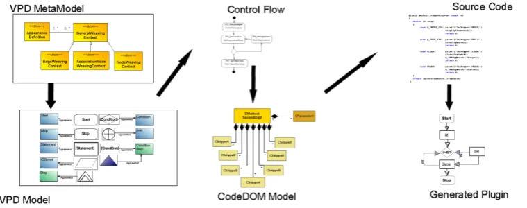
VMTSPresentation DSL (VPD) is aPresentation DSLrealized in VMTS. Fig.1shows the main steps of the concrete syntax definition and processing.
Figure 1: Concrete Syntax Definition - Overview
Code-DOM is an abstract code representation. From the CodeCode-DOM model, source code is generated with the .NET CodeDOM technology [TH03]. The source code implements a plug-in that can be used directly in VPF. This approach made it possible to avoid manual coding, and create plug-ins in a user-friendly, graphical way in the same environment as common DSL models. The paper [MLHVL06] has presented the VMTSPresentation DSLin detail, [MLHC06] has given an overview about the method, but the model transformation has not been introduced in detail. This paper fills this gap and introduces both the transformation control flow and the transforma-tion rules. Terminatransforma-tion properties of the transformatransforma-tion are also discussed in detail.
2
Related work
The Generic Modeling Environment (GME) [LBM+01] is a highly configurable metamodeling tool supporting two layers: a metamodel, and a modeling layer. The concrete syntax definitions can be coded either manually, or set by properties both on the metamodel and on the model level. GME supports a special type of property definitions: the registry entries. These entries are assigned to model elements and they can also customize the appearance.
Meta-CASE editors (e.g. MetaEdit+ [MEDIT]) are environments capable of generating CASE tools. They allow creating the tool definitions in a high-level graphical environment, but they supply a manually coded user interface. These environments store concrete syntax definitions in the metamodel properties.
Another framework is the Diagram Editor Generator (DiaGen) [DIAGEN], which is an ef-ficient solution to create visual editors for DSLs. DiaGen is not based on metamodeling tech-niques; it uses its own specification language for defining the structure of diagrams. DiaGen supports editing the concrete syntax in a graphical context, but in a tree control-based form only, where there is no support to define the shape of the elements graphically. Concrete syntax in DiaGen is based on properties. DiaGen can generate an editor based on the specification using hypergraph grammars and transformations.
AToM3 (A Tool for Multi-formalism and Meta-Modelling) [LV02]) is a flexible modeling tool. It employs an appearance editor to define the shape of the model elements graphically; it uses model level properties to store the concrete syntax (model definitions are extended with visualization-based attributes). AToM3 can generate plug-ins that use the defined syntax, but the code generation is not based on aPresentation DSL. The views of the models are generated with triple graph grammars.
Eclipse [ECLIPSE] is probably the most popular, highly flexible, open source modeling plat-form that supports metamodeling. The Eclipse Modeling Framework (EMF) can generate source code from models defined by the class diagram definition of UML, but it does not contain con-crete syntax definitions. The Graphical Editing Framework (GEF) is also a part of the Eclipse project. GEF provides methods for creating visual editors. EMF does not support code genera-tion for GEF, therefore GEF plug-ins require manual coding to support the concrete syntax.
that implements a plug-in based on GEF. VL specifications can be created graphically. Java is the only language supported in plug-in generation. At the moment TIGER can generate editors for Activity Diagrams and Petri nets.
The Graphical Modeling Framework (GMF) is also an Eclipse project. The goal of GMF is to form a generative bridge between EMF and GEF, whereby a diagram definition is linked to a domain model as an input to the generation of a visual editor. GMF uses a Presentation DSL to define the concrete syntax. The result (the linked concrete, and structural definitions) are processed further to produce source code. The mapping between the domain model and the model items of the concrete syntax is also supported in GMF. The generated source code relies on the features of GEF and EMF. Although the concept of GMF is straightforward, it has some weaknesses: (i) the generation is not based on model transformation. Consequently, the compilation steps are coded manually, thus, changing the transformation needs changing the source code and rebuilding the compiler. In case of model transformation such modifications can be accomplished at run-time. (ii) Because of EMF, GMF is restricted to Java only.
3
Defining the concrete syntax
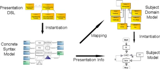
Concrete Syntax Models, namely concrete syntax definitions are created by instantiating VMTS
Presentation DSL(VPD).Concrete Syntax Models define how the model items of theSubject Model, namely, the models of the subject domain are visualized, and how they behave. Fig. 2
shows the metamodel - model, and the structural definition - concrete syntax relationships.
Figure 2: Structural definition - Concrete Syntax Relationship
3.1 The VPD metamodel
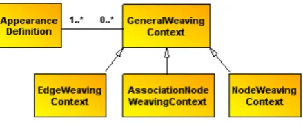
The VPD metamodel consists of five nodes as shown in Fig. 3. Appearance Definition can describe the graphical notation of the model elements. Weaving Contexts are used to define be-havioral attributes and to store mapping information between the concrete and the structure def-inition. The nameWeaving Contextdescribes that these elements weaves two different aspects of the model, the data and the visual definition, namely the abstract and the concrete syntax. For example, in case of ControlFlow diagramsAppearance Definitions define the graphical notation, such as rectangle for statement, or diamond for conditions.Weaving Contexts have a reference to the appropriate metamodel item, thus,StatementContexthas a reference toMetaStatementitem in the ControlFlow metamodel.Weaving Contexts also contain behavioral attributes, such as the minimum size of the model element. A relation betweenWeaving ContextandAppearance Defi-nitions can be constructed usingAttribute Referencerelations. In the metamodel, the multiplicity of this relation is many-to-many, which means that the appearance definitions are reusable, and the weaving contexts can have several appearances. This reusability is necessary because mod-eling languages have a tendency to use the same notation in different languages. For example StartState in UML statechart diagrams and InitialState in UML activity diagrams are denoted the same way. Similar separation between the behavioral attributes and the mapping information could be created, but we have found that customized behavioral attributes are harder to reuse. For example,Inputpins should be aligned to one side of its container in activity diagrams. This property is handled by behavioral attributes (positioning constraints). The constraints describe alignment rules useful only for this type of elements.
Figure 3: VMTS Presentation DSL - Metamodel
contain several primitives, for example an Actor in a Use-case model is defined in a single Re-gionalthough it consists of several primitives (head, body, arms, legs). More information on the VPD metamodel and concrete syntax definition can be found in [MLHVL06].
4
The transformation
Several techniques exist to create source code from a given model. Model transformations can be modeled in a visual way, they can be changed easily and they can use the efficient graph transformation techniques, along with high level transformation constraints, thus, they are one of the most popular solutions. VMTS uses Visual Model Processors (VMPs) to process models with graph rewriting-based transformation techniques. The inputs of a VMTS VMP are the input model and metamodel, the output metamodel, and the control flow model which defines the transformation. The result of the transformation is the output model. The input model is an instance of the input metamodel, and the output model is an instance of the output metamodel. Fig.4shows an overview of model transformation.
Figure 4: Model Transformation in VMTS - Overview
and join items. Model transformation algorithms often require parameter passing between the subsequent transformation rules. In VCFL, external causalities can be defined to pass parame-ters. In the next sections, we elaborate on the control flow and the corresponding steps of the VPD transformation.
4.1 VPD transformation overview
The control flow of the model transformation is shown in Fig. 5. The first rewriting rule ( Cre-ateNamespace) is an initialization step for the further operations. The second step ( GetUnpro-cessedNode) searches for an unprocessed weaving context in the host model, namely, in the
Concrete Syntax Model. If it does not find any, then there is no item to process in the model, thus the transformation ends. If there is an unprocessed model item, then the next step ( MatchAppear-ances) pass the associatedAppearance Definitions using theAppearance Relations to navigate, and generates the required CodeDOM items. The control flow uses external causalities and dec-orates the host model to pass the matching information between the rewriting steps to indicate the current context.
Figure 5: VMTSPresentation DSL- Control Flow
4.2 The transformation rules
added to the matched elements during model transformation [ML+06]. Using virtual attributes, the original model items can be decorated without changing their meta definitions. Virtual at-tributes are removed at the end of the transformation. In this case the ruleGetUnprocessedNode
is based on the virtual attribute IsProcessed. The weaving context in LHS is extended by an OCL constraint that ensures that the matched node has not been matched before. The rule also contains a modify type internal causality. Internal causality is a relationship between LHS and RHS nodes, and they define attribute computations. This causality adds theIsProcessedattribute to the matched node. The ruleMatchAppearances is more complex (Fig. 6). It matches the weaving context along with the associated appearance definitions. TheContextelement of the LHS is passed to the rule from theGetUnprocessedNoderule using an external causality. An ex-ternal causality is a parameter passing mechanism which facilitates to assign a host graph node matched to an RHS element to an LHS element of a subsequent rule. The matching algorithm considers these assignments compulsory. A single weaving context can have multiple appear-ances as mentioned before, thus the relation has a multiplicity of 1..*. The matched context and appearance CodeDOM elements are generated in the RHS. The rule consists of create type internal causalities only.
Figure 6: The ruleMatchAppearances
From the weaving context, three classes (type declaration), a Model, a View and a Controller class are generated according to the MVC-architecture used in VPF [MLHPF05]. The funda-mental types, namely, the types of the weaving contexts result in different base classes. For example, anAssociationNodeWeavingContextcreates type declarations inherited from Associa-tionNodebase classes defined in VPF. Binding between the structural definition and the plug-in items is constructed by an attribute containing the ID of the target model item according to the requirements of VPF. Other properties and methods of the classes are defined only if they over-ride the default behavior. EachAppearance Definitiongenerates a method in the View class. The methods are called when the model item is drawn out. The main loop of the transformation exits if the CodeDOM model is complete. The stepClearHelperInformationdeletes theIsProcessed
action,After Actionthat is executed at the end of the transformation. This special action is used to process the CodeDOM model and generate the plug-in. VMTS offers a built-in method to apply this task. The generated plug-in can be used directly in VPF.
Fig. 7shows two examples: the well-known FlowChart and the Nassie-Schneidermann plug-in that were constructed usplug-ing the plug-introduced method. The concrete syntax was defplug-ined plug-in two steps: (i) the notation of the model items were created in a graphical notation editor; (ii) mapping and behavioral properties has been added, such as position constraints for contained elements in Nassie-Schneidermann diagrams. Then, the concrete syntax definition was transformed to source code by a Visual Model Processor, based on the presented control flow. The transformation was not customized for the models, thesametransformation is used foreverydomain. The generated source code, namely the plugin was compiled, and used to edit the models. The time spent with the construction of the plugins was approximately seven times less, than it would be using manual coding. The FlowChart example is described in more detail (focusing the construction of the concrete syntax, and the generated source code) in [VMTS].
(a) (b)
Figure 7: Example plug-ins - (a) Nassie-Schneidermann (b) Flowchart
5
Termination analysis
Using a model transformation to convert the concrete syntax definition into source code is a straightforward solution, because changes in the framework or in the modeling structure can be easily adopted. ’Easily’ means that coding can be avoided; only the transformation con-trol flow and the rewriting rules need to be modified. In contrast, classic model to source code compilers would fail for example if a new fundamental type is required. This flexibility has also some drawbacks: if the transformation changes, then its correctness must be proven again. Using constraints in transformation rules can help in creating a validated model, but there are transformation-level properties, such as the question of termination, which require further exam-ination. The aim of our analysis is to prove that the transformation terminates for every valid finite input model. We use the definitions and theorems presented in [LPE06] to make the prov-ing method simpler. These theorems are proven to injective rules only, but this is not a problem, because the VPD transformation uses injective matches only.
Definition 1 An E-concurrent production p∗is an E-based composition if there is at least one
input graphG0with an E-related transformationG0 p∗ +3
Definition 2 Consider a possibly infinite sequence of graph productionspi, (i=1,2, ...) and a
sequence of E-dependency relations((Ei,e∗i,ei+1))leading to a sequence of their E-based
com-positions(p∗i = (L∗i ←Ki∗→R∗i))with p∗1=p1andp∗n= (p1∗E1p2)∗E2...∗Enpn.
A cumulative LHS series of this sequence is the graph seriesL∗nconsisting of the left-hand side graphs of p∗n. Moreover, a cumulative size series of a production sequence is the nonnegative integer series|L∗n|.
Theorem 1 A GT S= (P)terminates if for all infinite cumulative LHS sequences(L∗i) of the graph productions created from the members of P, it holds that
lim
i→∞
|L∗i|=∞.
Note that we assume finite input graphs and injective matches.
Proposition 1 The transformation VPD (depicted in Figure5) always terminates.
Proof. At first the transformation rules are examined whether they can affect the termination. The initial, final step, and theCreateNamespaceandClearHelperInformationrules are executed only once. They are not exhaustive, thus, they do not affect the termination. In contrast, the loop containing theGetUnprocessedNode, the decision object and theMatchAppearancesstep are critical. When the transformation is running, the loop is executed untilGetUnprocessedNode
can be matched. We unify the execution of consequent rules in the loop, namely we create the E-based composition of the rules, a new rule that has an equivalent effect on the host graph. The key of the proving method is to show that this unification produces an LHS sequence that exceeds all limits. Recall that the basics of the proving method is borrowed from [LPE06].
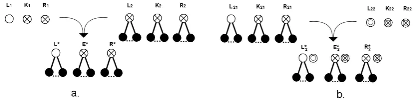
The first step in the E-based composition is to unify a single execution ofGetUnprocessedNode
andMatchAppearances. Fig. 8/a shows the composition in detail. No other composition struc-ture is valid, because of the external causality between the rules. Empty and crossed circles represent weaving contexts, the cross in the circle means that theIsProcessedattribute is set to
true. Filled circles are used to show appearance definitions. The generated CodeDOM model is not shown, because the CodeDOM model is just an output model, nodes in the CodeDOM model are never matched in the rules of the transformation. Next, the composition is further composed by the next step in the loop. In this case the first rule is the composite rule, the another rule is
GetUnprocessedNode. The composition step is shown in Fig.8/b. The new weaving context has an additional circle to show that it is different from the original one. It can be seen thatR21and
L22cannot be the same node, becauseR21has theIsProcessed attribute set to true, it cannot be
Figure 8: E-based composition
6
Conclusions
While structural definitions of DSMLs can be constructed in an efficient yet user-friendly way using metamodeling, handling the concrete syntax does not have such a well-accepted method. Our approach is a way to solve this problem. Previous work [MLHVL06] has presented the VMTS Presentation DSL, a domain-specific modeling language that can express concrete syn-tax definitions. This paper has completed the introduction of our approach by presenting the model transformation method that can create plug-ins from the concrete syntax definitions. The transformation control flow and the transformation rules were also presented in detail, including the examination of the termination properties of the transformation. The presented technique grants that the constraints enforced in the metamodel are treated separately from presentation of the concrete syntax. We have provided a simple, expressive model transformation based on graph rewriting to process the VPD models. The presented approach is easier and faster to use than manual coding. The presented transformation is flexible enough to convert the model to source code automatically. It has also been shown that the transformation always terminates. The presented transformation andPresentation DSLhave been successfully used in practice to model several domains, such as FlowChart, Nassie-Schneidermann, and UML Activity diagrams. Thus, the introduced open issues have been solved.
Different visualization states for model items are currently supported by attaching several ap-pearance definitions to a single context. These definitions are transformed to method definitions in the source code, but current version does not support modeling dynamic behavior: always the default appearance is used. The generated plug-in can be customized by a few lines of code, but our aim is to eliminate coding. The behavior and the different states of the model items can be modeled as a statechart diagram and attaching this behavioral information to the static visualization definitions can solve the problem. Thus, future work focuses on a higher level of automatization.
Bibliography
[MLHVL06] Mezei, G., Levendovszky, T., Charaf, H.: A Domain-Specific Language for Visu-alizing Modeling Languages, In Proceedings of the Information Systems Implementation and Modelling conference, Prerov, Czech Republic, 2006, pp. 67-74.
[VMTS] VMTS Official Homapage, http://vmts.aut.bme.hu/
[MLHPF05] Mezei, G., Levendovszky, T., Charaf, H.: A Presentation Framework for Metamod-eling Environments, Workshop in Software Model Engineering, Montego Bay, Jamaica, 2005 (to appear)
[LL+06] Lengyel, L., Levendovszky, T., Mezei, G., Charaf, H.: Control Flow Support for Model Transformation Frameworks: An Overview, In Proceedings of the MicroCad conference, Miskolc, Hungary, 2006, pp 193-199
[TH03] Thuan, T.,Hoang, L.: .NET Framework Essential, O’Reilly, 2003.
[MLHC06] Levendovszky, T., Mezei, G., Charaf, H.: Automatized Concrete Syntax Defini-tion For Domain Specific Langauges, InternaDefini-tional Conference on Technical Informatics, Timisoara, 2006
[LBM+01] L´edeczi, ´A., Bakay, ´A., Mar´oti, M., V¨olgyesi, P., Nordstrom, G., Sprinkle, J., Karsai, G.: Composing Domain-Specific Design Environments, IEEE Computer 34(11), Novem-ber, 2001, pp. 44-51
[MEDIT] Meta-case official homepage, http://www.metacase.com/
[DIAGEN] Minas, M.: Specifying Graph-like diagrams with DIAGEN”, Science of Computer Programming 44: pp 157-180, 2002
[LV02] de Lara, J., Vangheluwe, H.: AToM3 as a Meta-Case Environment, 4th International Conference on Enterprise Information Systems, 2002, pp 642 - 649
[ECLIPSE] The Eclipse Modeling Framework Framework, http://eclipse.org/
[GENGED] GenGed, tfs.cs.tu-berlin.de/ genged/
[EEHT] Erhig, K., Ermel, C., Hansgen, S., Taentzer, G.: Generation of Visual Editors as Eclipse Plug-Ins, http://www.tfs.cs.tu-berlin.de/ tigerprj/papers/
[Roz97] Rozenberg, G.: Handbook on Graph Grammars and Computing by Graph Transforma-tion: Foundations, Vol.1 World Scientific, 1997.
[ML+06] Mezei, G., Lengyel, L., Levendovszky, T., Charaf, H.: Extending an OCL Compiler for Metamodeling and Model Transformation Systems: Unifying the Twofold Functional-ity, 10th International Conference on Intelligent Engineering Systems, 2006