Proceedings of the
5th International Workshop on
Formal Methods for Interactive Systems
(FMIS 2013)
Lightweight Interaction Modeling in Evolutionary Prototyping
Anke Dittmar and Reik Schachtschneider
12 pages
Guest Editors: Judy Bowen, Steve Reeves
Managing Editors: Tiziana Margaria, Julia Padberg, Gabriele Taentzer
Abstract: The paper discusses a systematic integration of evolutionary and ex-ploratory prototyping of interactive systems by a lightweight use of formal meth-ods. Formal models guide the development of the underdesigned evolutionary pro-totype. In combination with techniques from Design Rationale, they implement the exploration and assessment of possible solutions to open design questions. Mod-els and corresponding tool support are used to express design options and to make them more accessible to a broader audience by the creation of parallel model-guided throwaway extensions of the current evolutionary prototype. They are also used to describe design constraints (for example, in terms of tasks or in terms of actions on artifacts) and to assess design options against these criteria. The suggested approach is demonstrated through an example design scenario that shows an intertwining of different design activities and discusses the role of formal models. In particular, the scenario describes a coupling of HOPS models, QOC diagrams, and Java prototypes.
Keywords:Interaction design, formal modeling, design rationale, prototyping
1
Introduction
Formal approaches have been used in HCI since the 1980ies to specify and produce interactive systems and to reason about them. Interactor concepts such as [Abo91] are early examples of formalisms for specifying the relation between the internal and the observable behavior of inter-active software systems. The GOMS family are well-known approaches relying on formal meth-ods to analyze human computer interaction from a cognitive perspective [Joh03]. The formaliza-tion of general design principles supports a better understanding of systems, and in some cases, allows to automate reasoning processes (e.g. [MRO+13]). Model-based design approaches ex-ploit formal task and domain models in a prescriptive way to produce user interfaces [Pat00] and SwingStates [AB08] is an example for integrating a formal notation into programming practices of advanced interaction techniques. Formal methods help to abstract from implementation de-tails and to focus on those properties of an interactive system that are of particular interest in a certain design context. “A formal model may suggest new ways of looking at a system design, new ways of evaluating it, new ways of inventing features and new ways of improving human computer interaction” state the authors in [HT90].
Another limitation is that not all participants in multidisciplinary design teams are familiar with formal notations and that formal approaches are often perceived as limiting the creativity of in-teraction designers [Dix91]. A deliberate integration of formal methods into design processes is often suggested to mitigate these limitations and to increase the acceptance of formal approaches beyond domains such as the domain of safety-critical systems.
The paper investigates a lightweight use of formal interaction modeling in an evolutionary prototyping process of interactive systems. It is assumed that some of the design issues that emerge during such processes require an in-depth exploration and assessment of options. An integrated use of design rationale, formal methods and prototyping is suggested to support these exploration steps. Formal models are applied for different purposes in this process. They serve to specify alternative extensions of the evolutionary prototype and to implement corresponding parallel model-guided prototypes, but they can also be used as a means for assessing options and for planning next steps in the design process.
The tight coupling between different design representations supports the members of a (multi-disciplinary) design team in developing a shared understanding of the design space and in making decisions on how to extend the current prototype. For example, a potential user may not be able to fully express some desired temporal behavior of the system, but another team member would respond by creating two or three possible formal models and by mapping them to the evolu-tionary prototype. During model animation, a model would partly control the behavior of the prototype. These alternative model-guided prototypes are accessible to all members.
The paper continues our work presented in [DP13] where a coupling scheme between QOC diagrams (Questions, Options, and Criteria), HOPS models (Higher Order Processes Specifica-tions), and Java implementations is introduced to demonstrate the applicability of the proposed co-evolution of design representations for Design Rationale, formal HCI models, and prototypi-cal implementations for analytiprototypi-cal and empiriprototypi-cal design space exploration. This paper puts more emphasis on the consideration of the overall design process and the various roles formal mod-eling can play in it. Section2 gives an overview of the suggested approach and describes its background in related work. In Section3, a small design scenario is developed to explain the approach in more detail. The paper closes with a summary and future work.
2
Background
According to [Dia04], design is a goal-directed activity requiring models of both the current and the envisaged world. The paper particularly considers design processes that involve a tight inter-play between problem setting and problem solving [Sch83]. It is suggested that a co-evolution of models describing aspects of the current and the envisaged world and of prototypical imple-mentations of the interactive system under design supports this interplay.
2.1 Overview of the Design Approach
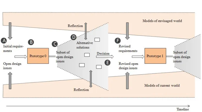
Figure 1: Overview of the model-guided prototyping approach. The evolutionary prototype is depicted in the boxes labeled ‘Protoype 0’ and ‘Prototype 1’.
the problem and possible solutions needs to be obtained. Such design questions are explored by the development and assessment of alternative solutions to extend the evolutionary prototype. Formal models are used in exploration steps for the following main purposes:
- to specify those aspects of the evolutionary prototype that are addressed by a design question, - to specify essential aspects of a suggested solution more precisely and at a conceptual level, - to specify aspects of the current and envisaged world that constrain the solution space, - to compose models according to the coupling scheme in [DP13].
Throughout this paper, we will use the coupling scheme for QOC models, Java implementa-tions and HOPS models that is introduced in [DP13] to support an integration of design rationale activities and evolutionary prototyping by formal modeling. However, any other formal notation with similar features and tool support like HOPS and with corresponding implementation lan-guages is a candidate for the suggested approach. In particular, it should be possible to compose models, to map them to prototypical implementations, and to animate them in order to facilitate model-guided prototyping [DP13]. Similar to [DH10], model composition and the animation tool is also used for assessing design ideas against design constraints.
O-models in such a way that model animation implements parallel model-guided prototypes which can be evaluated analytically and empirically by using (formal and informal) C-models of the current and envisaged situation (D). In addition, an O-model can be enriched by implementation details which do not need to be considered at a conceptual level but which make the model-guided throwaway extension of the evolutionary prototype more accessible.
On the one hand, C-models influence the creation of the evolutionary prototype. On the other hand, the exploration of new design ideas changes the view on the problem setting and encour-ages further analysis of the current world and of possible design goals and constraints. The designers refine their understanding of the usage context of the artifact and consequences of de-sign decisions (revision of C-models). A decision for one alternative has to be made (E), the requirements and the set of open design issues have to be revised (F), the evolutionary proto-type has to be enhanced accordingly and so on. It is essential in this iterative process to avoid premature commitments to particular solutions and to explore alternatives.
A small design scenario is used in Section3 to provide a more detailed picture of the ap-proach. It demonstrates how the interactive artifact under design (in the example, an interactive puzzle game) emerges from coupling three types of design representations: QOC diagrams for exploring and evaluating design options, prototypical Java implementation, and HOPS models. In particular, the central role of formal models will be discussed more thoroughly. The scenario will illustrate an intertwining of exploratory, analytical, empirical, and implementation activities.
2.2 Related Work
Our approach draws on a variety of sources. In User-Centered Design, iterative approaches and prototyping are generally recommended to achieve active involvement of users and other stakeholders. However, a systematic development of the prototypes in use is often missing. As a consequence, it can be difficult, for example, to overcome bad initial design decisions. In [DFAB03], the use iterative design “in conjunction with other, more principled approaches to interactive system design” is recommended. Operational prototyping [Dav92] is an interesting approach even if the focus is more on ‘classical’ software engineering practices. Davis suggests to lay throwaway prototyping dealing with poorly understood requirements atop an evolutionary base which implements well-understood requirements. In this paper, a better integration be-tween evolutionary prototyping and exploratory steps is proposed by the concept of deliberate underdesign.
Dow et al. show that iterative prototyping refines ideas, but can also give rise to design fix-ation. Parallel prototyping helps designers to discover unseen design constraints, to produce better results and to gain more task-specific self-confidence [DGK+10]. This paper puts parallel prototyping into a systematic exploration and evaluation of design spaces for selected design is-sues by applying the QOC notation that is well-known from Design Rationale (DR) [MYBM91]. HOPS models are used as means to couple the representations of argumentation processes and throwaway extensions of the current prototype [DP13].
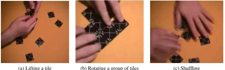
(a) Lifting a tile (b) Rotating a group of tiles (c) Shuffling
Figure 2: A person playing with the cardboard version of the puzzle.
manipulate and reason about design options within a formal development process [Bra95]. A perhaps less rigor approach is taken in [Joh96]. Here, Z specifications are related to options in the QOC notation. On the one hand, design questions and criteria of QOC diagrams provide a rationale for these specification fragments. On the other hand, the specifications provide precise descriptions of possible solutions. The Dream-Team tool [LPB+06] aims to support the trace-ability of design decisions. QOC diagrams can be enriched by task models related to options and scenarios of task models can be associated to criteria. It is not quite clear, though, whether the task models in [LPB+06] are not rather system models. In the suggested approach, the emphasis is not on the integration of formal methods and design rationale but on a systematic development of underdesigned prototypes. Formal models are used to describe and to prototype possible ex-tensions without modifying the existing evolutionary prototype. This can help to avoid premature design decisions. The HOPS tool extends the idea of model animation and allows to selectively control Java prototypes by animating HOPS models. In model-guided prototyping [DP13], only those aspects of interaction are formalized that need to be discussed at a more conceptual level.
The HOPS formalism has roots in task notations and related animation tools (e.g. [Pat00]), but additionally provides means to describe interactive systems as compositions of sub-systems [BMDD00]. Model composition enables the reflection of a system from different viewpoints [DH10] which is needed for the formal description of design questions, options, and criteria of QOC diagrams. Our approach supports the idea of multidisciplinary modeling [BSMH95].
3
Model-Guided Prototyping Processes
In this section, a design scenario is described to explain the above ideas in more detail. Figure2
3.1 Initial Representations
Let us assume that, in a first analysis of the current cardboard version of the puzzle, the focus has been on the actions that players perform on single tiles and on groups of tiles. They rotate tiles, they drag them on the table, and sometimes they lift and drop a tile. They also drag or rotate groups of tiles or divide them, and Figure2(c) shows a player shuffling a group. The HOPS model in Listing2 describes this action-oriented view on the current world. There are operations specifying actions on tiles and operations specifying actions on groups of tiles. In the model, no temporal constraints are imposed on the execution of these actions. In contrast, the model in Listing1reflects a more task-oriented perspective. It describes that players achieve the goal of the taskSolvePuzzleby positioning tiles in two ways in the 3x3 target grid. They either first select a place in the grid and then look for a matching tile or vice versa (sub-processes FillGridPlaceandFindGridPlacelines 15-16). Let us assume that these are the models of the current world that initially guide the design.
For the interactive version of the puzzle, there are at least three issues that should be explored more deeply: (1) the design of the playing area, (2) the behavior of single tiles (in terms of user actions), and (3) user actions on groups of tiles. The first prototype has to be underdesigned with respect to these design questions in order to avoid premature commitments to solutions.
Listing 1: Task-oriented view
1 PROCESS Current_1
2 OPS 3 selectTile(), 4 lookForPlace(), 5 selectPlace(), 6 lookForTile(), 7 removeTile(), 8 solved(), 9 giveUp(),
10 SUB PROCESSES
11 Current_1 IS SolvePuzzle,
12 SolvePuzzle IS (LayOutTile [] removeTile())*
13 [> (solved() [] giveUp()),
14 LayOutTile IS (FindGridPlace [] FillGridPlace),
15 FindGridPlace IS selectTile() ; lookForPlace(),
16 FillGridPlace IS selectPlace() ; lookForTile(),
17 END PROCESS
Listing 2: Action-oriented view
1 PROCESS Current_2
2 OPS
3 drag(e:string),
4 ...
5 SUB PROCESSES
6 Current_2 IS
7 MoveTile ||| MoveGroup,
8 MoveTile IS (liftDrop("t")
9 [] drag("t")
10 [] rotate("t")
11 [] dragRotate("t")
12 [] liftDropRotate("t"))*,
13 MoveGroup IS (rotate("g")
14 [] drag("g")
15 [] divide("g")
16 [] shuffle("g"))*,
17 END PROCESS
3.2 Underdesigned Prototype and Selected Design Questions
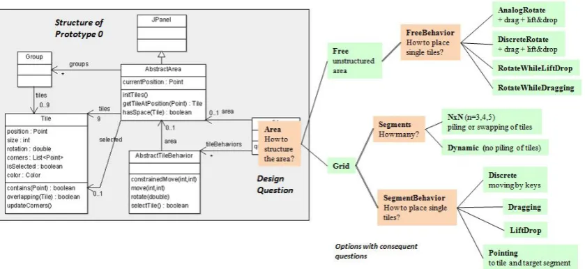
The class diagram in Figure3presents the overall structure of the first version of the evolutionary Java prototype (set and get methods are omitted). It implements tiles on a playing area but abstracts from a concrete structure of the area and from concrete user actions on tiles and groups of tiles. The abstract classesAbstractAreaandAbstractTileBehaviorare used for underdesign and have to be specialized in later extensions of the prototype.
imple-Figure 3: Class diagram of the initial Java prototype (on the left) and question-option structure of an associated QOC diagram (on the right)
ment possible solutions to the selected design questions. It is responsible for setting concrete sub-classes ofAbstractAreaandAbstractTileBehavior. The coupling is controlled by a composition of HOPS models which is illustrated at examples in the next subsection and described in detail in [DP13].
3.3 Exploration of Design Options
The key question in the QOC diagram on the right of Figure3is: How to structure the playing area? Two options (labeled by ‘Grid’ and ‘Free’) are given. For reasons of simplicity, criteria are not shown in Figure3and will be discussed later. Consequent questions concern the way how the area should be segmented (fixed or dynamic number of segments) and how tiles should behave in free areas and in grids. Corresponding options can be formalized by HOPS models. For example, the following sub-process specifies separate and analog rotating and dragging actions on tiles that are performed over a period of time.
AnalogRotate IS
((startRotate() ; stopRotate()) [] (startDrag() ; stopDrag()) )*
Questions, options and, optionally, criteria are represented by HOPS models which are com-posed according to the structure of the QOC diagram. In addition, the HOPS model that repre-sents the key question (labeled by ‘Area’ in the example) is mapped to the ‘coupling’ class of the underdesigned prototype (classAreain the example). Now, the HOPS tool allows to switch between different design options and to animate them on top of the existing prototype. Listing3
shows the model composition that was generated for the exploration of discrete tile behavior in dynamically sized grids (see lines 21-22 and Figure3).
Java methods (lines 6-12) and by mappings of Java events to HOPS operations (lines 14 ff). The animation of the model in Listing3 results in a model-guided prototype. Only those aspects of the prototype are controlled by the HOPS model that are specified in the options. Figure4
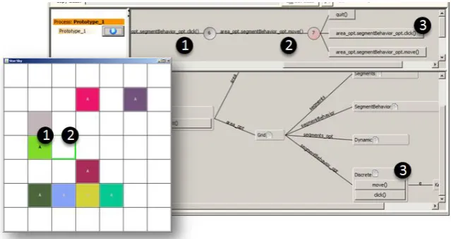
depicts an animation run with the Java prototype in the foreground and the HOPS animation tool in the background. The composition tree in the bottom part of the animator visualizes the current model composition with selected options ‘Discrete’ and ‘Dynamic’ (compare with Figure3). As another example, the composition in Figure5 extends the existing prototype by the option ‘RotateWhileDragging’ in unstructured playing areas. Back to Figure4, the model controls the users’ movements in the grid, the rotation of tiles, the selection of a tile and its target segment. These interactions and their sequencing are specified in an abstract way by HOPS operations (lines 6-13 in Listing4) and sub-processes (lines 18-23). Enriching implementations are provided by the mapped Java class. For example, arrow keys are used to move in the grid and tiles are rotated in 90 degree steps.
Listing 3: Generated model composi-tion for animating opcomposi-tionDiscrete
1 PROCESS Prototype_1
2 BASIC COMPS
3 // key question
4 area: Area,
5 // selected option
6 area_opt: Grid(area),
7 ...
8
9 PROCESS Area -> question.Area
10 OPS
11 // connect to initial prototype
12 init() IS FCreate(),
13 ...
14
15 PROCESS Grid(area: COMP(Area))
16 BASIC COMPS
17 // follow up questions
18 segments: Segments,
19 segmentBehavior: SegmentBehavior,
20 // selected options
21 segments_opt: Dynamic(area),
22 segmentBehavior_opt: Discrete(area)
23 ...
Listing 4: HOPS model of optionDiscrete
1 PROCESS Discrete(area: COMP(Area))
2 -> options.beh.SegmentedDiscreteBehavior
3 VAR lifted: INT = 0,
4 BASIC COMPS e: MouseEvent,
5 OPS
6 move() IS void.FCall("move",e),
7 click()
8 COND (lifted==0)
9 IS lifted.FCall("detSource")
10 COND (lifted==1)
11 IS void.FCall("detTarget"); lifted.set(0),
12 rotate() IS void.FCall("rotateInSlot"),
13 ...
14 EVENT MAPPINGS
15 area : keyPressed(37) -> move(),
16 ...
17 SUB PROCESSES
18 Discrete IS init() ;
19 ((move() [] rotate())* ; click() ; Cont)*
20 [> quit(),
21
22 Cont COND (lifted==1) IS move()* ; click()
23 OTHERWISE IS Skip,
24 END PROCESS
3.4 Assessment of Design Options
Models of current and envisaged worlds such as those given in subsection3.1 have multiple functions. On the one hand, they enable the generation of ideas because they help designers to constrain their view of a design problem. For example, the options in the scenario that rely on segmented areas may have emerged from a task-oriented perspective while those for unstructured areas closely follow currently observed actions with the cardboard puzzle. On the other hand, these models are means for assessing alternative solutions and for changing perspectives. In other words, they can also be used as criteria in a QOC representation.
Figure 4: Model-guided prototyping of option ‘Discrete’ in dynamic grids. The animation tree in the top part of the HOPS tool shows the performed operations: (1) selection of a tile - click, and (2) go to the left - move, as well as the currently enabled operations (3) that can also be activated in the Java prototype by using keys. In the current state, the rotation of tiles is not enabled by the model (see also Listing4).
need to formalize a criterion ‘all tiles are visible’ to see that it is not supported by options where tiles can be piled and that it is not fully supported if tiles can be moved in a lift-drop metaphor (as to be seen in Figure5). In the model fragment below sub-processMoveTileof Listing2is used to assess option ‘RotateWhileDragging’ (compare Figure3). Again, model composition is used and operations from the criterion process (in bold) are mapped to HOPS operations describing appropriate user actions in the design solution. This mapping and the animation run of Figure5
reveal that not every action on tiles that is possible in the current world is supported by the design option (in the figure, (5) marks unbound operations of the criterion process). However, analogical transfer is not always desirable in design.
PROCESS RotateWhileDragging(area:COMP(Area))
-> options.beh.RotateWhileDragging BASIC COMPS
criterion: MoveTile>>Current 2, ...
OPS
liftDrop()
COND (lifted == 0) IS lifted.FCall("lift",e)
COND (lifted == 1) IS void.FCall("drop",e)... ; criterion.liftDrop("t"), startRotateDragging()...,
stopRotateDragging() IS ... ; criterion.dragRotate("t"), ...
END PROCESS
Figure 5: Model-guided prototyping of option ‘RotateWhileDragging’. Lifted tiles cannot be rotated: (2) to (3). Tiles can be rotated during dragging but may collide with other tiles (4).
dragging is specified to be a constrained movement that does not allow overlapping tiles. When a dragged tile collides with another tile (indicated by (4) in Figure5), the latter keeps its position in the associated throwaway prototypes. However, while testing the prototype one can easily find out that such constrained movements may be convenient for positioning tiles in a (not visible) solution grid but can be experienced as annoying when tiles are just dragged in the free space. This observation may lead to a refined view on current practices and design constraints.
3.5 Refined View on Problem and Design Space
A more detailed picture of the different meanings of tile movements in the example may include that players also drag, lift, drop, rotate tiles to bring them into or out of focus, to study their structure or to order them. Moreover, the interaction with the prototype in Figure5may reveal an assumption in the initial prototype. While the player in Figure2uses both his hands to push together two tiles, the design in Figure3 considers one current position only, e.g. the current mouse pointer (attributecurrentPositionin classAbstractArea).
The approach that was demonstrated at the example of HOPS models, Java prototypes, and QOC diagrams counterbalances well-known effects such as design fixation in iterative proto-typing or overspecification in formal modeling. The specification and actual implementation of design options for selected questions may prevent an unhealthy growth of the solution space, and the assessment of alternatives helps to think about assumptions made in the design process. It should be emphasized, though, that the consideration of design alternatives is not a dogma.
One question we would like to investigate in the future concerns the quality of evolutionary prototypes from an engineering point of view. While the combination of abstract models with enriching implementations results in more accessible models, it may also make implementations more accessible for a better structuring by developers. We would also like to gain more experi-ence with the techniques of underdesign and model-guided prototyping from this perspective.
Bibliography
[AB08] C. Appert, M. Beaudouin-Lafon. SwingStates: adding state machines to Java and the Swing toolkit.Softw. Pract. Exper.38(11):1149–1182, Sept. 2008.
[Abo91] G. D. Abowd.Formal Aspects of Human-Computer Interaction. PhD thesis, Oxford University Computing Laboratory, 1991.
[BH94] J. P. Bowen, M. G. Hinchey. Seven More Myths of Formal Methods: Dispelling Industrial Prejudices. InProc. of the 2nd Int. Symposium on Formal Methods. 1994.
[BMDD00] P. Barnard, J. May, D. Duke, D. Duce. Systems, interactions, and macrotheory. ACM Trans. Comput.-Hum. Interact.7(2):222–262, June 2000.
[Bra95] C. Bramwell. Formal Development Methods for Interactive Systems: Combining Interactors and Design Rationale. PhD thesis, University of York, UK, 1995.
[BSMH95] V. Bellotti, S. B. Shum, A. MacLean, N. Hammond. Multidisciplinary modelling in HCI design... in theory and in practice. InProc. of CHI ’95. Pp. 146–153. ACM Press/Addison-Wesley Publishing Co., 1995.
[Dav92] A. M. Davis. Operational Prototyping: A New Development Approach. IEEE Softw.9(5):70–78, Sept. 1992.
[DGK+10] S. P. Dow, A. Glassco, J. Kass, M. Schwarz, D. L. Schwartz, S. R. Klemmer. Paral-lel prototyping leads to better design results, more divergence, and increased self-efficacy.ACM Trans. Comput.-Hum. Interact.17(4):18:1–18:24, 2010.
[DH10] A. Dittmar, M. Harrison. Representations for an iterative resource-based design approach. InProc. of EICS ’10. Pp. 135–144. ACM, New York, NY, USA, 2010.
[Dia04] D. Diaper. Understanding Task Analysis for Human-Computer Interaction. In Dia-per (ed.),The handbook of task analysis for human-computer interaction. Lawrence Erlbaum Associates, Inc., 2004.
[Dix91] A. Dix.Formal Methods for Interactive Systems. Academic Press, 1991.
[DP13] A. Dittmar, S. Piehler. A Constructive Approach for Design Space Exploration. In Proc. of EICS 2013, to appear. 2013.
[HT90] M. Harrison, H. Thimbleby. The role of formal methods in human-computer in-teraction. In Harrison and Thimbleby (eds.),Formal Methods in Human-Computer Interaction. Pp. 1–8. Cambridge University Press, 1990.
[Joh96] C. W. Johnson. Literate specification: using design rationale to support formal methods in the development of human-machine interfaces. Hum.-Comput. Inter-act.11(4):291–320, 1996.
[Joh03] B. John. Information Processing and Skilled Behavior. In Carroll (ed.),HCI Mod-els, Theories, and Frameworks: Toward a multidisciplinary science. Pp. 55–101. Morgan Kaufman Publishers, 2003.
[LPB+06] X. Lacaze, P. Palanque, E. Barboni, R. Bastide, D. Navarre. From DREAM to Re-ality: Specificities of Interactive Systems Development With Respect To Rationale Management. In Dutoit et al. (eds.),Rationale Management in Software Engineer-ing. Pp. 155–172. Springer Berlin Heidelberg, 2006.
[MRO+13] P. Masci, R. Ruknas, P. Oladimeji, A. Cauchi, A. Gimblett, Y. Li, P. Curzon, H. Thimbleby. The benefits of formalising design guidelines: a case study on the predictability of drug infusion pumps.Innovations in Systems and Software Engi-neering, pp. 1–21, 2013.
[MYBM91] A. MacLean, R. M. Young, V. M. E. Bellotti, T. P. Moran. Questions, options, and criteria: elements of design space analysis.Hum.-Comput. Interact.6(3):201–250, 1991.
[Pat00] F. Paterno. Model-Based Design and Evaluation of Interactive Applications. Springer, 2000.