Learning and Training Techniques in Laboratory
about Power Factor Compensation
Mariana Iorgulescu
Electronics, Computers and Electrical Engineering Departament University of Pitesti, Romania
Abstract—The power system contains very different processes, characterized by multiple parameters. The engineers that operate in this domain must be prepared to act without fail. Over a few years of experience this study introduces a concept of learning in the field of power system training. This concept is implemented in a power system laboratory. The other purpose of this study is to bring the needs of the companies closer to schools.The paper presents techniques of power factor compensation learning as an important component of electric engineering education.
In the present project the student is going to know the parts of the components of the electrical installations used and their operating principles. Based on this, the student is going to identify the reactive power quantity absorbed from the electrical network by the industrial operator, then establish the power factor compensation method and, finally, test the compensation obtained by measurements and calculations. Also, the student will indicate the neutral value of the power factor.
Keywords- learning, training , power factor compensation.
I. INTRODUCTION
An energy system represents all the electrical and non-electrical installations with which primary energy is converted into electricity and is used by these installations.
For a faultless functioning and a quick solution to any emerging problems in the energy system it is imperative for operators to have the necessary training. This also requires operators to understand both the physical phenomena that accompany the functioning of the system and the equipment used in power plants. The training of operators has become an important issue to be faced by power systems in order to update knowledge and skills.
The main purpose of the work of teachers is to provide engineers in the industrial environment with a suitable technical training in order to certify operators in knowledge, skills, expertise and abilities in connection to operating power systems.
The process of learning to control the power factor, maintain the neutral value and diagnose the faults in the industrial field is a challenge for future engineers. The challenge is even greater when the complexity of the system affects the efficiency, reliability and safe operation.[1]
The power factor is of special interest to the electricity producer, the carrier, the distributor, the supplier and to the end user as well, because it affects the performance characteristics of all operators on the electricity market, the cost of the electricity supply, and the ability to transfer energy equipment available.
In any electrical installation there are two types of electricity: active electrical energy that is consumed by any electrical/electronic and electric reactive, which is
due to magnetic circuits in the network. Reactive power is inherent in any system of common energy power, generating pollution of the power quality, which results in a high cost of the electric bill from the provider. In addition to this, when sizing each circuit of the power grid the electric supplier must consider additional streams introduced by this reactive power.
This paper presents a training program in electrical engineering which is meant for the industrial field and aims to decrease the energy costs by the power factor compensation method. The methods and program of training can be presented like:[2]
lectures;
different types of exercising;
face-to-face teaching and e-learning through lectures, group discussions, problem-solving tasks and independent studies;
a laboratory simulator for hands-on classroom training;
testing and validation
The overall structure of the study takes the form of three sections, including the introductory section. The second section describes the basic elements of power factor compensation from a theoretical point of view. The third section presents the practical power factor activities in laboratory work that is, designing the power factor compensation for an industrial operator and managing the experimental equipment. Finally, the conclusion gives a brief summary of the learning and training in the area of power factor compensation.
II. BASIC ELEMENTS OF POWER FACTOR
COMPENSATION A. Power factor definition
Electrical equipment is designed to operate at a certain apparent power (S). Depending on the structure of the power consumer and the flow of the power system, power is accompanied by movement of active power (P), reactive power (Q) and deforming power (D) - according to C. Budeanu's definition.
The relationship between the following three types of power:
apparent (S), active (P) reactive (Q),
can be expressed as the power triangle trigonometric presented in Figure 1.
φ
Q [VAr]
S [VA]
P [W]
Figure 1Triangle of electric power
[W] (1)
[VAr] (2) The definition given by Budeanu C. (1927) is based on the apparent power broken down into two terms orthogonal:[3]
S=√ [VA] (3) ign ± corresponds to reactive power – inductive or capacitive.
The term cosφ from active power equation is called power factor and is defined as the ratio between active power and apparent power. The power factor is less and ranges between 0 and 1.
The power factor is a result of the use of incomplete transfer capacity of the elements of the power system, given that electrical installations are designed to transfer the apparent power (electricity), but the consumer receives an active power (power output) which is lower if the power factor is low.
The neutral power factor is the average monthly power factor value established by law which a consumer should achieve in order to be exempt from reactive energy. The neutral power factor is determined periodically based on power system studies for a certain stage of development of the national energy system, taking account of the pricing of electricity and the cost of the compensation equipment.
In Europe there is a tendency to assess the reactive power consumption by:
(4)
- called reactive power factor, which better reflects the real value of dynamic reactive power variation than cosφ. For example, if cosφ is changed from 0.95 to 0.94, the reactive power changes by 10%, and with the change from 0.99 to 0.98, the variation of the reactive power is 30%.
B. Improving Power Factor
An inductive load with low power factor does occur in generator systems and there appears a reactive current in the transmission/distribution, accompanied by a loss of strength and power outages. If a load capacitor is added parallel to the load, this capacitive reactive current will follow the same route as the current existing reactive circuit previously.
The consequences of low power factor are:
•distribution facilities are sized according to the current transited, corresponding apparent power;
•reactive power regime is handled directly and influences voltage levels and losses within electrical networks;
•reactive power through power factor affects the electricity bill consumers.
C. Purpose of improving the power factor
Reducing energy costs
Good management of reactive energy consumption brings considerable economic benefits. These considerations are based on the current structure of tariffs usually applied in Europe, designed to encourage beneficiaries to lower consumption of reactive power.
Installing capacitors for reactive power compensation in order to reduce expenses enables consumers to electricity by maintaining the reactive power consumption below a certain value, agreed by the energy provider contract. In this type of tariff, reactive energy is paid according to the criterion of tgφ.
In order to benefit from the above mentioned advantages, the consumer must consider the cost of purchase, installation and operation of reactive power compensation capacitors, the protective equipment and command the circuit breaker together with additional kWh consumption due to losses in dielectric capacitors, and so on.
It may be more economical to only make a partial compensation and pay for part of the reactive energy, in order to gain more benefit than with a 100% offset. Generally, power factor correction is an optimization problem, except for some very simple cases.
Technical and economic optimization
A higher power factor optimization of components allows an installation. Oversizing the equipment can be avoided, but in order to get the best results correction should be made as close as possible to each inductive component equipment.
D. The advantages of improving the power factor
Power factor improvement allows the use of transformers, cables and smaller devices while reducing losses and voltage drop of an installation.
Reducing losses (P, kW) in cables
Losses in cables are proportional to the square of the current and are measured in kWh meter. For example, reducing the current in a conductor with 10% will lower the losses by about 20%.[7]
(5)
(6)
- active power losses
(7)
- power losess produced by reactive and
deforming power flow
( ) (8)
So, increased with the power factor decreased
according to (9):
(9)
Reducing the voltage drop
Mounted capacitors for reactive power compensation reduce or even cancel inductive reactive current in upstream conductors, thereby reducing or even eliminating voltage failures, according to equation (10) [6].
√ √
Where:
– drop voltage corresponding of active power
drop voltage-term corresponding of reactive and deforming powers
The other problem it is overcompensation that will produce an increase in voltage on the capacitor.
Increasing the power available
Several active power values correspond to the same value of apparent power, depending on the consumer’s power factor:
and (11) If , then:
(12)
So the active power increased, , with the decrease of the reactive power.
In improving the power factor of a load supplied from a current, the transformer will be reduced, allowing the addition of other tasks. In practice it may be more advantageous to improve the power factor than to replace the transformer with a larger one.
E. Measures taken to improve the power factor may include:
Technical -organizational measures, with which the power factor is increased without investment, using natural means;
Special measures, by using specialized reactive power sources.[4],[5]
Natural means of improving the power factor
mainly consist in eliminating the causes that lead to a power factor below the optimum, analyzing the situation of each consumer in hand, choosing and operating of appropriate electrical equipment and choosing the configuration and network structure of the electricity distribution.
Special means for improving power factor consist of installing reactive energy sources and installing of filters in order to limit the negative effects of the distorting power.
Most commonly used power factor compensation solutions for industrial consumers are:
- Capacitor banks; - Harmonics filters;
- Static compensators (Static Var Compensator-SVC). Capacitor banks have a number of advantages
including:
- They are static installations with reduced size; - Low active power losses of about 0.003 kW /kVAr (about 10 times lower than synchronous compensators);
- Can be installed with some simple training; - They do not increase the short circuit power; - They require maintenance and special supervision; - Specific cost is 3-5 times lower than the synchronous compensators (EUR/ kVAr);
- Can be constructed and operated in steps in order to achieve a reasonable compensation;
- Manufactured for low and medium voltage.
When using capacitor banks, some disadvantages arise:
- Reactive power can be changed in steps; - Surges to connect and disconnect steps;
- Reactive power available battery voltage capacitor depends on the square;
- Cannot be used in harmonic pollution power grids;
- The repair is very difficult.
Components of bank capacitor are presented in the next section.
A bank capacitor consists of:
- Actual capacitors for power factor correction, forming steps battery. If the networks require a quick response to load variation, thyristors are a solution:
- Controller for power factor correction;
- Special contactors for switching capacitive loads; - Disconnectors with fuses;
- Control and protection panel comprising secondary circuits for the control and protection of the capacitor;
- The power supply circuit;
- Forced ventilation (only for reactive powers more); - Antiresonance filters (only for polluted networks with harmonics).
They can be installed as part of the console to make general.
This equipment can also be placed in a separate cell of the general desk or added in the console's common housing. There are variant and the capacitors.
1
S
1
2
2S
1
Q
2
Q c P
c
Q
Figure 2. Diagram for determining the reactive power
If the power factor of a handset is cosφ1 and for technical and economic reasons it is necessary to compensate up to the cosφ2 value, it follows that the reactive power compensator element (condenser or coil) is determined:
( ) (13) If the handset is inductive (actually the most common case) then the compensating element (capacitor) has a value according to the equation:
( ) (14)
The compensation and inductance element (coil) is obtained similarly if the consumer is capacitive:
( ) (15)
The notations are according to the diagram presented in Figure 2.
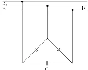
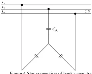
In three-phase networks, the capacity of the bank capacitors depends on their connection mode: triangle or star, Figures 3 and 4.
1
L
3
L
2
L
U
C
1
L
3
L
2
L
U
C
Figure 4 Star connection of bank-capacitor
Produced reactive power is given by:
( ) (16)
Where,
-U represents network voltage, in kV
-C- bank capacity, in F
- m-coefficient with value 1 in star connection and 3 in triangle connection.
III. PRACTICAL ACTIVITIES IN POWER FACTOR COMPENSATION
A.Study case: Design of automated bank for power compensation of industrial consumer
The industrial consumer for which the power factor is improved is a metalworking company. Consumers in the workshop have powers in the range of 6.5-24 kW, with a total of 200kW installed power. An average of 0.62 power factor has been recorded (according to the electricity supplier invoice). The purpose is to achieve a neutral power factor of cosφ neutral = 0.92 for the consumer industry, value for which the company will not be penalized by the electricity supplier.
In the studied case a global compensation was performed for the automatic capacitor battery by placing it in a single area for the entire installation. The capacitor is connected to the main switchboard bars of the low voltage distribution facility that remains in operation and the operation is rated.
The power of the bank capacitor is determined by the formula[4]:
(17)
Where:
-Qc is the reactive power consumed at neutral power factor;
-Q1 is the reactive power given by the formula:
(18)
-tgφ-tangent value corresponding to the neutral power factor:
√( ) (19)
On the other hand, analysing the reactive power on an hourly basis, Q2, we see that this varies between 6.2 and 50 kVAr.
Finally, considering the economic criteria, a bank capacitor with 5-steps automatic compensation to Qc = 168.75 KVAr will be purchased.
The above case study further needs to discuss the results of improved power factor and compare the characteristics of the electrical installation before and after applying the power factor compensation.
The industrial operator before power factor correction is characterized by the following facts[7]:
The reactive energy registered is expensive due to low power factor of cosφ = 0.62;
The apparent power is significantly higher than the active power;
The current produced corresponding to the reactive power losses is payable;
The electrical installation must be oversized.
Before the power factor correction the parameters of the facility are:
Power transformer S = 250kVA P = 200kW, cos φ = 0.62
Apparent power consumption as in formula:
(20) In this case the power transformer operates at overload. Circuit current, according to:
√
√ (21)
Cable losses, Joule losses, are proportional to the square of the current, as in:
(22)
Reactive power transformer is supplied by conductors facility, so the power transformer, circuit breaker and wiring are oversized at cosφ = 0.62.
After the installation of power factor correction the parameters are:
Reactive power consumption is eliminated (cosφ = 0.922), so charging penalties for exceeding reactive energy consumption are eliminated.
Load is determined based on apparent power demand and is set according to the amount of reactive power absorbed.
Facility characteristics are:
Power transformer: S = 250kVA for installed power P = 200kW and cos φ = 0.92.
Apparent power consumption, presented in:
(23) In this case the transformer is not overloaded, but 87% loaded.
Circuit current, established in:
√
√ (24)
Cable losses are reduced by the ratio 45.4% from the previous losses, gaining reactive power economy.
Reactive power is supplied by battery reactive energy compensation. The reactive power of the plant is 168.75 kVA, automatically controlled at 5 speeds.
B.Experimental stand for power factor correction
For practical work, a bank of automatic reactive power compensation was designed and capacitors for power factor of inductive consumers were used, as follows:
-three lighting mercury and electromagnetic ballast with a rated power of 400 W, cos φ = 0.56;
-universal AC motor, wound rotor, Pn = 2kW, cos φ = 0.80.
The rated supply voltage network is 230V and there is a maximum rated current of 6A.
M
C
KM
DA
PFC6
TC
Hz V/50 230
Figure 5. Electrical circuit for reactive power compensation
The electrical circuit of the experimental bank for reactive power compensation is presented in Figure 5.
By installing the automatic capacitor batteries, it is proposed to achieve a power factor of inductive consumers selected from cosφ = 0.56 minimum value to neutral factor.
Figure 6. Electrical wiring of regulator for automatic power factor control
The electrical wiring of the regulator for automatic power factor control is presented in Figure 6. [6]
In the beginning the student knows general information about handling equipment and overall operation of the equipment, as presented in the next section.
Current and voltage are recorded through the A/D converter system and this information is used to calculate the relationship between active and reactive power. The controller works in four quadrants.
During the initialization phase the reports from measuring the current transformers capacitor steps value and phase sequence are verified by successive connection and disconnection. Inaccurate readings that may result from the simultaneous connection of capacitors and tasks can be prevented by using the option of measuring its own current transformer separately mounted on the entrance to the installation of compensation.
In order to achieve the correction factor it is necessary to calculate the permanently programmed power. Switching capacitor steps takes place in accordance with this correction, if the difference exceeds 70% of the
power at the smallest stage. Optimal correction requires fewer shifting operations.
Using the current measurement input option compensation system to measure the current of the transformer can monitor power, current and harmonic currents. If step defects or excessive harmonic currents appear, the controller will display error messages and if programmed properly, it can even disconnect the system from the network.
During work the student must pay attention to the following aspects:
Which could be the main problems?
Another problematic situation could appear due to the misconnection of the current transformer, controller or capacitors in the circuit resulting in permanent damage of these elements.
The capacitor banks are to be used only after some measurements regarding the existence and the size category of the deformations.
The functioning mode of the bank capacitor will be correlated with automation existing in the laboratory. The student should be aware that the factory might have, for instance, ARR (Automatic Release of Reserves).
The possibility of the emergence of the resonance phenomenon on the higher harmonics should also be verified, as that would result in the damage of the compensation equipment.
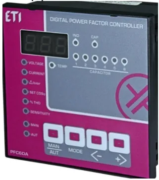
Figure 7 Front panel of digital power factor controller
The second step of the practical activity represents setting the value of the power factor using the front panel of the controller, as it is presented in Figure 7 [6]. The student will then complete the following steps:
Identify the buttons and the measure displayed on the digital power factor controller;
Use the manual or automatic mode of operating for the digital power factor controller;
Set the value of the power factor;
Put the digital power factor controller into operation and record the characteristics;
IV. CONCLUSIONS
This project is important in the learning and training process because the students following it get acquainted with the main operations required to:
Design the bank capacitor for power factor compensation for an industrial consumer;
Use the bank capacitor installation.
This subject is important in the industry of power systems because by working on power factor compensation students build both technical and software skills required to operate at the work place. Including real situations of the work environment ensures that the skills acquired are those needed on the labour market.
In the near future the competences gained by the student once this project has been performed will be analysed.
REFERENCES
[1] Knowlege-Based and Intelligent Information and Engineering Systems Volume 6882 of the series Lecture Notes in Computer
Science pp 94-103, Liliana Argotte,Yasmin Hernandez,Gustavo Arroyo-Figueroa, Intelligent E-Learning System for Training Power Systems Operators, Chapter · eptember 2011,DOI: 10.1007/978-3-642-23863-5_10
[2] S.Tretsiakova-McNally, E. Maranne,F. Verbecke,V. Molkov ,Mixed e-learning and virtual reality pedagogical approach for innovative hydrogen safety training of first responders, International Journal of Hydrogen Energy, 42 (2017) 7504 -7512 [3] Carmen Ionescu Golovanov,Sorin Dan Grigorescu, Ioana- Izabela
Odor,Nicolae Trogmaer, Aspecte privind implicarea metrologiei legale la masurarea puterii/energiei reactive in sistemul electroenergetic , METROLOGIE, vol.LIII (serie nouă), 2006, nr. 1 - 4
[4] Energetic Prescription PE 120/94
[5] Khushboo Arora , Vivek Saxena , Sanjeev Sain, A Comparative Study and Analysis of Power Factor Correction Methods, International Journal of Emerging Technology and Advanced Engineering, Website: www.ijetae.com (ISSN 2250-2459, ISO 9001:2008 Certified Journal, Volume 4, Issue 5, May 2014) [6]
http://www.etigroup.ro/images/userfiles/ro-RO/documents/products/building_industry/Promotional%20data/P FC-power-factor-controllers.pdf