Section 1: About Your ORBIT-Pro
I
I
n
n
t
t
r
r
o
o
d
d
u
u
c
c
t
t
i
i
o
o
n
n
t
t
o
o
t
t
h
h
i
i
s
s
M
M
a
a
n
n
u
u
a
a
l
l
This ORBIT-Pro Installation and Programming Manual is designed to take you through the required steps so you can successfully install the ORBIT-Pro and have it perform as desired. To this end, the manual is divided into two distinct installation and programming sections. The first of these, beginning on page 11, discusses how to install and wire the panel to its peripherals. The next section, beginning on page 26, covers the programming of the panel using an attached keypad.
While not required for these purposes, the following documents are also available to assist you in the installation of your ORBIT-Pro.
DOCUMENT PART NO. DESCRIPTION
The ORBIT-Pro Installer
Programming Worksheets 5IN296PW
a series of tables for recording the programmed data unique to an account
The ORBIT-Pro Upload/Download
Programming Manual 5IN296UD
explains how programming can be done through the use of an IBM®-compatible Personal Computer
The ORBIT-Pro User’s Manual 5IN296UM provides information intended for ORBIT-Pro’s end users
A
A
b
b
o
o
u
u
t
t
t
t
h
h
e
e
O
O
R
R
B
B
I
I
T
T
-
-
P
P
r
r
o
o
The ORBIT-Pro is a full-featured security system and provides sophisticated solutions for protecting, alerting, and reporting premises’ alarm signals, intended to address the needs of virtually every home, office, and commercial facility. It is designed around microprocessor and EEPROM (Electrically Erasable Programmable Read-Only Memory) technology–which will store, without the need for power, the system’s operating program as well as its programmable parameters. The ORBIT-Pro supports most standard detectors and sensors, along with a variety of accessories and output devices.
It can provide monitoring and supervision for up to 96 zones. Through its 4-wire BUS, it can support a variety of optional modules including multiple Keypads, Zone Expanders, a Wireless Interface, supplemental Power
Supply(ies), a Digital Voice Module, capabilities for Access Control, an X-10 Interface, and Utility Outputs. All these devices communicate with the system by sending commands and data over the BUS, which originates at the Main Board.
The ORBIT-Pro utilizes commercial electricity as its primary means of power and supports a rechargeable standby battery. Its components and features are listed below:
Main Board
The Main Board is the center of the system’s operation. It supports 8 hardwired zones, provides continuous auxiliary power for detectors like PIRs, and other peripherals (e.g. Audio Switches and certain Shock and Glass-Break Sensors) which require it. The Main Board also maintains a source of resettable power for Smoke Detectors when latched in the alarm state. It supplies power for the operation of an external sounder and offers the
appropriate type of voltage for an electronic siren(s), a bell(s), or a loudspeaker(s). Up to 20 Zone Types are supported.
Zone terminations include Closed-Circuit, Open-Circuit, End-of-Line (EOL) Resistor, and Double End-of-Line (DEOL) Resistor (see Figure 2-4 on page 22).
It is from the Main Board that the 4-wire BUS originates and from which all system expansion takes place (see Figure 2-6 on page 24).
Zone Expansion
In addition to its eight hardwired zones, the ORBIT-Pro can support up to another 88 such zones (96 total) which are derived through the connection of either 8-Zone or 16-Zone Expansion Module(s), including the Wireless Expansion Modules (not for UL Installations) discussed below.
Wireless Expansion
When it's either necessary or desirable to utilize wireless zones, the ORBIT-Pro's Wireless Expansion Modules will respond to Rokonet's own NOVA transmitters and to Orbit’s Rolling Code Transmitters.. The Wireless Module employs superheterodyne technology, has programmable supervision time, detects a low battery condition in transmitters, tamper attempts, and provides indications of signal jamming. Wireless and hardwired zones may be mixed in the same system, with the total of all zones (hardwired plus wireless) limited to 96.
Partitions
Any zone or group of zones can be assigned to any of 8 independent partitions. Partitioning allows a single ORBIT-Pro to protect each dwelling in a multi-family house, several departments in a commercial or institutional facility, and even several closely situated stores a strip mall. Each partition supports zone-sharing and cross-zoning.
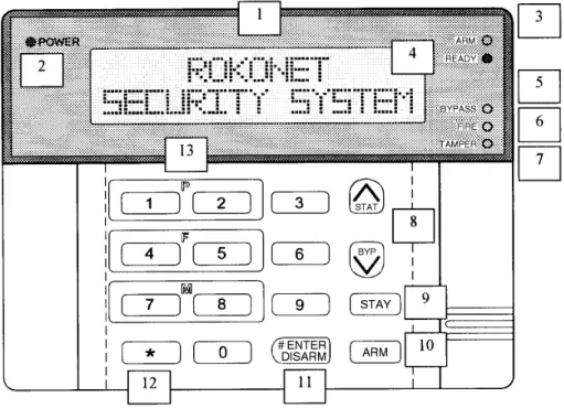
Keypads
The ORBIT-Pro can support up to 16 keypads, with a choice of four styles (two LCD-type and two LED-type) from which virtually all system features may be accessed.
The LCD Keypads come in two styles: Custom Plus (shown here), with a large display and Custom (with a smaller display).
The LED Keypads also come in two styles: 16 Zone (shown here), with 16 Zone LEDs and 8 Zone (with 8 Zone LEDs).
Each keypad is equipped with three Emergency Key zones (Panic, Fire, Auxiliary Emergency) and the ability to produce a Duress (Ambush) Code. All keypads are tamper-protected and employ backlighting for their display and their keys, which also produce audible feedback when pressed. Keypads can be programmed to detect and discourage unsuccessful attempts at disarming, and incorporate easy-to-use hot-key sequences for simple zone bypassing and to display information about unsecured zones. A one key Quick-Arm feature, for both "Stay" and "Away" modes of operation, can be selected for ease of use.
In partitioned systems, keypads can be selectively assigned to specific partitions, but LED-type keypads can be used only in systems, which do not exceed their ability to display zone indications. Thus, the 8-LED Keypad (p/n RP296KL8) cannot be used in a system with more than 8 zones, nor can the 16-LED Keypad (p/n RP296KL16) be used when more than 16 zones are installed.
User Codes and Authority Levels
Each ORBIT-Pro installation typically accommodates up to 99 unique User Codes of up to 6 digits each–each code assignable to one of several Authority Levels and, if used, to multiple partitions.
Keyswitches (Not for UL Installations)
For those premises locations in which a simple keyswitch will suffice, the ORBIT-Pro is capable of supporting an
Expansion Bus
Through the ORBIT-Pro’s 4-wire BUS, which can be run up to 1000 feet, a variety of features and enhancements are made possible through the use of the appropriate Expansion Module(s). Incorporating any module into the system is accomplished by its simple connection to the system's BUS, as suggested by 2-6 on page 24.
Programmable (Utility) Outputs
An “open-collector” transistor output has been incorporated into the ORBIT-Pro’s Main Panel to help operate an external device in response to a number of system activities related to alarms, zones, partitions, the actions of a particular user, or scheduled events based on the system’s internal clock.
A door-strike, a CCTV Time Lapse recorder, an “intermediate relay” will be necessary (see page 8 for additional information).
When more output flexibility is required, this single output can be augmented through the use of two types of Programmable Output Expansion Modules:
• the 4-output relay module (using four programmable Form C relays)
• the 8-output switching module (using eight open-collector transistor outputs)
X-10 Module (Not for UL Installations)
The ORBIT-Pro also supports the connection of an X-10 Transmitter Module to its 4-wire Expansion Bus. X-10 technology converts the ORBIT-Pro’s programmable output events into a protocol understood by the Transmitter Module. When so triggered, this module generates activation and control signals along existing AC premises wiring to the appropriate X-10 Receiver Modules–appropriately placed and connected within the premises to control lighting and appliances. X-10 Transmitter Modules are available for the ORBIT-Pro supporting either 8 or 16 premises Receiver Modules.
Digital Communicator / “Follow-Me” Mode
The ORBIT-Pro's on-board Digital Communicator is capable of numerous transmission formats, including
ADEMCO Contact ID and SIA. It can process up to 8 account numbers (i.e. one for each partition) and store up to three Central Station phone numbers–should multiple or split reporting be utilized. In addition to standard
communication with the monitoring station, the ORBIT-Pro employs a Follow-Me feature, in which a phone call can be made–using tones to represent the active alarm (e.g. burglary or fire)–to adesignated phone number. This feature is available for each partition and is generally useful for informing a homeowner at work, or a business owner at home, that there has been an alarm at a specific premises.
With the optional Digital Voice Module, it's possible to record a short message, which replaces the alarm tones normally produced in the Follow-Me mode.
The communicator also offers a "batch" mode from which non-urgent reports can be collected over a designated time period, and then transmitted all at once. The communicator also supports daily system testing, along with reports of entry into (and exit from) the system's Installer Programming mode.
Finally, a Paging Feature is available through the Follow-Me mode. If selected and programmed to do so, ORBIT-Pro messages containing the following information can also be sent to a user’s numeric or alphanumeric pager : partition-based opening and closing signals and/or partition-based alarm signals
Power Supply Expansion
Although the ORBIT-PRO’s Main Board provides 600 mA of auxiliary power, 250 for Switch Aux and 900 for Bell, the use of a number of additional system modules and detectors will likely exceed this limitation. As a result, the ORBIT-Pro permits the addition of up to eight remoteable Power Supply Expansion Modules, each operating from AC power and connected to the 4-wire BUS.
Each such module provides a total current capacity of 1.5 amperes and has connections for powering auxiliary devices and triggering either bell(s), electronic siren(s), or loudspeaker(s) during an alarm. Each Power Supply Module also supports its own standby battery, and is supervised for the loss of AC, a Low Battery condition, the failure of its auxiliary output power, and the loss of sounder loop integrity.
Digital Voice Module (Not for UL Installations)
The Digital Voice Module is an unique component, which provides two useful services. It permits premises’ telephones and/or cellular phones to act as keypads, and/or it can also equip the ORBIT-Pro for Central Station two-way listen-in capability. It's also used to enhance the aforementioned Follow-Me feature, already described.
Access Control Expansion Module (Not for UL Installations)
One of ORBIT-Pro's most unique features is its ability to interface with an on-premises Access Control sub-system. With a maximum connection of eight such Access Control Modules–each supporting up to two readers–a total of 16 readers is possible, each of which may operate with magnetic, proximity, bar code, touch, and/or Weigand technology. Up to 500 users can be accommodated and up to 1200 "transactions" can be stored.
Scheduling
Through the use of the system's built-in clock, it's possible to schedule automatic arming and disarming (of one or more partitions) at the same time on selected days of the week, or at a specific time within the subsequent 24-hour period. Up to 20 vacation periods can be programmed.
Event Logging
By itself, the panel has the capability of storing up to 128 significant events, including arming, disarming, bypassing, alarms, troubles, restorals, and resets. These events are logged in order according to date and time, and when applicable, according to Zone, Partition, User Code, Keypad, etc. Optional Event Log Expansion Modules are available to store 512 and 999 events, respectively. When appropriate, such events can be displayed on an LCD Keypad or uploaded to the alarm company via the Upload/Download software and printed for further analysis.
Sensor Auto-Testing (Not for UL Installations)
Sensor Auto-Testing provides for the automatic testing of a selected group of up to 16 sensors in the installation at one (or more) selected times during the day. If all the related sensors are triggered within a selected window of time, the Auto-Test will be considered successful. The results of the test will be logged in the Event Log, and reported to the Central Station, if so desired.
Printer Adapter Module (Not for UL Installations)
A printer module, designed to interface between the ORBIT-Pro’s 4-wire Expansion Bus and a Centronics-type parallel printer, will allow for the printing of all significant system events, as they occur, including Access Control activities (see above) if applicable. Each event will include the date, time, and if applicable, the affected partition and the user involved.
Bus Adapter Cable (Not for UL Installations)
With the Bus Adapter Cable assembly, a portable IBM®-compatible computer may be directly connected to the ORBIT-Pro and used for local Uploading/Downloading operations.
Program Transfer Module (Not for UL Installations)
The Program Transfer Module is a tiny printed circuit board capable of storing, without the need for power, the programmed configuration of any ORBIT-Pro. Therefore, if desired, one account’s programmed configuration–once loaded into the Program Transfer Module–can be used as a “template” and taken to another account, where the stored configuration may be “copied” and subsequently modified.
Self Monitoring
The ORBIT-Pro has a “watchdog” feature, which periodically and automatically performs a comprehensive self-test and reports when operating faults are found. The panel also has a Maintenance Mode which, when selected, performs an active self-check on many of its components. Its Bus Test allows the system to verify the connections and the operation of all Keypads and Expansion Modules, whose resulting reports, individually displayed as percentages on the LCD keypad (or via the Upload/Download software), indicate the efficiency of the unit under test. Results of less than 100% may be due to faulty wiring, poor connections, or component degradation. Such early detection can help to eliminate the potential problems later on.
The ORBIT-Pro also incorporates “one-man” walk testing capabilities, allowing an installer or technician to check the operation of each contact and detector which, when tripped, produces audible feedback and is visibly logged at the keypad from which the test was initiated.
False Alarm Reduction
In conformance with SIA's (the Security Industry Association) standards for deterring false alarms, the ORBIT-Pro provides the following programmable features:
• swinger shutdown
• audible/visual Entry/Exit delays
• fire alarm verification
• dialer delay before an alarm transmission
• cross zoning
Synoptic Map
A program running on a PC (under Windows-NT® Operating System) and connected to the ORBIT-Pro’s local bus, provides a graphic display of the whole system.
Forced Arming Zone (Not for UL Installations)
When this option is enabled (on a per-zone basis), the panel can force arming with these zones opened. If a forced zone is open, the “Ready” LED will blink and the zone will be bypassed at the end of the exit time. If the zone is closed at any time during the arm period, it will be automatically unbypassed and re-included in the system.
Figure 1-2, on page 6, provides an overview of the ORBIT-Pro’s architecture and capabilities. You may wish to look this figure over to obtain a “big picture” of the system before continuing.
I
I
n
n
v
v
e
e
n
n
t
t
o
o
r
r
y
y
S
S
u
u
p
p
p
p
l
l
i
i
e
e
d
d
w
w
i
i
t
t
h
h
t
t
h
h
e
e
O
O
R
R
B
B
I
I
T
T
-
-
P
P
r
r
o
o
The ORBIT-Pro is sold with one of four keypads, a metal cabinet, and various accessories. Figure 1-3 shows the typical packaging contents. Refer to Table 1-1, below, and Table 1-2, which begins on page 1-10, for further information.
Figure 1-3
ITEM DESCRIPTION
1 Metal Cabinet
2 Printed Circuit Board (equipped with hardware for mounting in metal cabinet)
3 Keypad (see the table within Figure 1-3) 4 Documentation, consisting of:
• ORBIT-Pro: Installation and Programming Manual (this manual)
• ORBIT-Pro: Installer Programming Worksheets (1 set)
• ORBIT-Pro: User’s Manual
5 Keypad Quick Guide (packaged within the keypad)
6 Assorted hardware, including 16 End-of-Line Resistors (2200Ω)
Table 1-1
Description: Panel and Keypad Product No. ORBIT-Pro with large LCD Display RP296P04 ORBIT-Pro with small LCD Display RP296P03 ORBIT-Pro with 16-Zone LED Display RP296P02 ORBIT-Pro with 8-Zone LED Display RP296P01
1
2
4
4
3
6
5
O
O
R
R
B
B
I
I
T
T
-
-
P
P
r
r
o
o
A
A
c
c
c
c
e
e
s
s
s
s
o
o
r
r
i
i
e
e
s
s
ITEM DESCRIPTION Keypads RP296KL8 8-LED Keypad RP296KL16 16-LED KeypadRP296KCS LCD Keypad, Custom (small display) RP296KCL LCD Keypad, Custom Plus (large display)
Zone Expanders
RP296EZ8 Zone Expansion Module (8-Zone) RP296EZ16 Zone Expansion Module (16-Zone)
Wireless Zone Expanders
RP296EW8 Wireless Zone Expansion (Receiver) Module* (8-Zone) RP296EW16 Wireless Zone Expansion (Receiver) Module* (16-Zone)
Power Supply Expanders
RP296EPS Power Supply Expansion Module
Programmable Output Devices
RP296EO4 Utility Output Expansion Module (4-Relay Outputs: Form C) RP296EO8 Utility Output Expansion Modules (8 Open-Collector Outputs)
Event Loggers
RP296EL5 Event Logger Expansion Module* (512 Events) RP296EL9 Event Logger Expansion Module* (999 Events)
Printer Module
RP296PRT Printer Module*
Digital Voice Module
RP296EDV Digital Voice Module*
X-10 Module
RP296XT X-10 Transmitter Module*
Uploading/Downloading
RP296UD Upload/Download Software* (for IBM Compatible PCs)
RP296EE Program Transfer Module
RP296BA Bus Adapter (Cable) used for local PC-based Uploading/Downloading operations: connected between a PC’s serial (COM) port and the ORBIT-Pro’s J1 connector; requires Upload/Download software (above) and includes a required converter adapter terminated in a female DB25-type connector (it may be necessary to obtain a 25-pin male to 9-pin female adapter if required by your PC’s COM Port)
Access Control
RP296EAC Access Control Module*
Miscellaneous
RP296MA/MB/MC ORBIT-Pro PC Board (only)
RP296B1 Metal Box for Main Board and 3 Expansion Modules RP296B2 Metal Box for Single Expansion Module
RP296B3 Metal Box for Multiple Expansion Modules
Tamper Switch
T
T
e
e
c
c
h
h
n
n
i
i
c
c
a
a
l
l
D
D
a
a
t
t
a
a
Control Panel
Input Power: 16.5 Volts AC @ 40 Volt-Amps (VA) (via transformer) Rechargeable Standby Battery: 12 Volts 6 Amp-Hours (AH), typical
Power Outputs Auxiliary Power: Switched Auxiliary: Bell/LS (External) Sounder Output:
12 Volts DC @ 600 mA, maximum
12 Volts DC @ 160 mA, max. for UL installations 12 Volts DC @ 250 mA, maximum **
12 Volts DC @ 80 mA, max. for UL installations 12 Volts DC @ 900 mA, maximum
** included in the 600 mA of Auxiliary Power
Programmable Voltage (Utility) Output: Open-Collector Active Pull-Down, 70 mA, maximum Cabinet Dimensions: 30.5cm x 29.7cm x 8.4cm
12.0 in x 11.7 in x 3.3 in Weight: 3.5 kg / 7.7 lbs.
Main Board Dimensions: 20 cm x 11.5 cm x 3.1 cm 7.9 in x 4.8 in x 1.2 in F1 responsible for: Auxiliary Power: Switched Auxiliary: Keypad Power: 1.0 A F2 responsible for: Bell/LS Power: 1.0 A Fuses: F3 responsible for: Battery Power: 3.0 A
Keypads
Current Consumption: 32 mA, typical / 72 mA, maximum
Control Panel Connection: 4-wire BUS, up to 1000 ft (300m) from panel Dimensions: 15cm x 11.6cm x 3cm
5.9 in x 4.6 in x 1.2 in Weight: 250 gr
0.55 lbs.
Zone Expansion Module: 8-Zone
Current Consumption: 25 mA, typical / 34 mA, maximum
Control Panel Connection: 4-wire BUS, up to 1000 ft (300m) from panel Dimensions: 10.5cm x 6.6cm x 1.8cm
4.1 in x 2.6 in x 0.7 in
Zone Expansion Module: 16-Zone
Current Consumption: 27 mA, typical / 34 mA, maximum
Control Panel Connection: 4-wire BUS, up to 1000 ft (300m) from panel Dimensions: 16.5cm x 6.6cm x 1.8cm
6.5 in x 2.6 in x 0.7 in
Utility Output Expansion Module: 4-Output
Current Consumption: 25 mA, typical / 140 mA, maximum Contacts: 4 Form C (SPDT) Relays
contact rating: 5 A / 24 Volts DC
Control Panel Connection: 4-wire BUS, up to 1000 ft (300m) from panel Dimensions: 10.5cm x 6.6cm x 2.2cm
4.1 in x 2.6 in x 0.87 in
Utility Output Expansion Module: 8-Output
Current Consumption: 25 mA, typical / 30 mA, maximum
Contacts: Open-Collector, Active Pull-Down, 70 mA, maximum Control Panel Connection: 4-wire BUS, up to 1000 ft (300m) from panel
Dimensions: 10.5cm x 6.6cm x 1.8cm 6.5 in x 2.6 in x 0.7 in
Power Supply Expansion Module
Input Power: 16.5 Volts AC @ 40 VA (via transformer) Rechargeable Standby Battery: 12 Volts 6 Amp-Hours (AH), typical
Power Outputs Auxiliary Power: Bell/LS (External) Sounder Output:
12 Volts DC @ 600 mA, maximum 12 Volts DC @ 900 mA, maximum
Control Panel Connection: 4-wire BUS, up to 1000 ft (300m) from panel Dimensions: 9.0cm x 9.0cm x 6.7cm
3.5 in x 3.5 in x 2.6 in
Event Log Expansion Module
Current Consumption: 25 mA, typical / 29 mA, maximum
Control Panel Connection: 4-wire BUS, up to 1000 ft (300m) from panel Dimensions: 10.5cm x 6.6cm x 1.8cm
4.1 in x 2.6 in x 0.7 in
Printer Module
Current Consumption: 7mA, typical / 10mA, maximum
Control Panel Connection: 4-wire BUS, up to 1000 ft (300m) from panel Dimensions: 6.2cm x 5.3cm x 1.6cm
2.44 in x 2.08 in x 0.6 in
X-10 Transmitter Module
Current Consumption: 25 mA, typical / 29 mA, maximum
Control Panel Connection: 4-wire BUS, up to 1000 ft (300m) from panel Dimensions: 10.5cm x 6.6cm x 1.8cm
4.1 in x 2.6 in x 0.7 in Table 1-3
Section 2: Installing Your ORBIT-Pro
It's easy to wire up the panel, its keypad(s), and any Expansion Module(s) you wish to install. In addition to the wiring, you will also have to do some preliminary physical programming on the system’s keypads and modules by setting some DIP switches. The entire process is discussed in this section.
Be sure the actual work is performed by experienced personnel, licensed to carry out security system installations and capable of implementing all applicable requirements of the National Fire Protection Association (NFPA-70 and NFPA-74), as well as any federal, state, and local codes–along with any safety guidelines and regulations which might apply.
M
M
o
o
u
u
n
n
t
t
i
i
n
n
g
g
a
a
n
n
d
d
W
W
i
i
r
r
i
i
n
n
g
g
t
t
h
h
e
e
C
C
o
o
n
n
t
t
r
r
o
o
l
l
P
P
a
a
n
n
e
e
l
l
(refer to Figures 2-1 and 2-7)
Mount the Control Panel’s metal cabinet at a dry location, near a source of unswitched AC Power, a good ground connection (see below, right), and access to the customer’s telephone service. Use the proper hardware (e.g. anchors, mollys, toggle bolts, etc.), as required, to insure a suitable mounting. See Figure 2-1 on page 19.
Thread all electrical wires through a convenient hole in the metal cabinet. To prevent potential damage, be sure that live AC power is NOT present and that the Standby Battery is NOT connected. Your wiring, described on the following pages, may include any and all of the following:
§ connections for the 4-wire BUS to include keypad(s) and Expansion Modules mounted either inside or outside the panel
§ connections for Hardwired Zones
§ connections to Auxiliary Power
§ connections to Smoke Detector (resettable) Power
§ connections to any External Sounder(s)
§ if used, the Utility Output (UO1) connection (typically, will trigger a low current DC device (e.g. a 12 VDC Relay, 70 mA, maximum) connected between the UO1 and the AUX /RED terminals (see page 8 for additional information)
§ connections from the RJ31X (or equivalent) telephone interface
§ the Ground Connection (see the box at the right)
§ connections for AC Power
What Makes a Good Ground?
Grounding provides a degree of protection against lightning and induced transients for any piece of electronic equipment which may, due to lightning or static discharge, experience permanent or general malfunctions. The ideal "ground" is considered to be a unified earth ground in which an 8-foot copper-clad rod, located close to the existing power and telephone ground rods, is sunk several feet into the earth. Appropriate hardware and clamps are then used to electrically connect each of these rods together, and then to the ground terminal of the device to be protected. Since this procedure is difficult in most cases, an alternative earth ground connection can be made to a conductive metal cold water pipe within the premises. Because such pipes ultimately route their way into the earth, the attachment, to the pipe, of a suitable metal clamp and a length of wire can make an effective ground connection for the ORBIT-Pro. Verify that the pipe is metallic throughout its entire run into the earth since much of today's plumbing is made from PVC (plastic) compounds. Do not use a hot water pipe for grounding because it will likely attach to a heating apparatus which may not, itself, be grounded.
It may be possible to use an existing electrical ground on the premises if one is close enough to the panel. Ideally, that ground can be obtained at the metal service panel where the incoming electrical power originates. When connecting the ground wire, use a solid 14-gauge wire [or larger (numerically lower) size] connected between the ORBIT-Pro’s GND terminal and run to an acceptable electrical ground connection. Keep this wire as short as possible and do not run it in conduit, coil it, bend it sharply, or run it alongside other wiring. If you must bend it or change its direction, it should have a radius of at least 8 inches at the point from which it is bent.
W
W
i
i
r
r
i
i
n
n
g
g
t
t
h
h
e
e
M
M
a
a
i
i
n
n
B
B
o
o
a
a
r
r
d
d
(see Figures 2-4, 2-6, 2-7 on pages 22, 24 and 25)
CONNECTION COMMENTS
Expansion BUS and
Keypad Connections
AUX (Red) COM (Blk) BUS (Yel) BUS (Grn)
§ the first four terminals at the left of the Main Board represent the system’s Expansion BUS, supporting the connection of keypad(s) and Expansion Modules
§ use a quality 4-conductor cable with an adequate gauge size (e.g. 22-18, see page 17) to accommodate any voltage drops which may occur when multiple keypads and long wire runs are employed (also see Figure 2-6 on page 24); for convenience, you may wish to match the wire colors to the BUS connections
§ additional branches of the Expansion BUS may be derived from any other point on the BUS (see Figure 2-6, page 24)
§ the maximum wire run permitted is 1000 feet for all legs of the BUS (see page 18)
Zone Wiring to Sensors and Detectors
Zone Terminals (Z1 through Z8)
§ connect the wiring for up to 8 hardwired zones using the wiring of your choice (e.g. twisted pair, 4-conductor cable)
§ each zone must be wired to the appropriate zone (Z) terminal and the adjacent common (COM) connection; for example, wire Zone 1 to the Z1 and COM terminals; wire Zone 2 to Z2 and the same (COM) terminal (see Figure 2-4, page 22, and Figure 2-7, page 25)
§ for supervision against short circuits, it's recommended (but not required) that you use a 2200Ω End-of-Line Resistor (16 are supplied) at the far end of each hardwired zone
§ unused zones must be terminated at the control panel according to how the zone is configured in the Installer Programming section of this manual (on page 35)
§ for intrusion detectors requiring power (e.g. PIRs, photoelectric systems, certain shock sensors, audio switches), you may want to incorporate the zone wiring and the power wiring in the same cable; if so, be sure you choose a wire gauge (e.g. 22-16) which takes into account the number of detectors and the amount of wire required
§ only 4-wire Smoke Detectors can be used with the ORBIT-Pro; 2-wire Smoke Detectors are not supported
§ for proper 4-wire Smoke Detector supervision, a Power Supervision Relay is required. Wire the relay according to the layout in Figure 2-7, (on page 25); by doing so, the loss of power to the detector(s) will de-energize the relay, cause a break in the zone wiring, and a subsequent “Fire Trouble” indication generated at the panel
Power to Auxiliary Devices:
Continuous Auxiliary Power AUX COM
(+) (–)
§ wire these terminals to power PIRs, glass-break detectors (4-wire types), audio switches, photoelectric systems, and any device whose operation requires a continuous supply of 12 Volts DC
§ do NOT use these terminals to supply power to Smoke Detectors; they must be powered by the Switched Auxiliary Power (see below)
§ wire should be of a suitable gauge (e.g. 22-16) to accommodate any voltage drop which might occur based on current requirements and distances involved
§ when many auxiliary devices are employed in an installation, consider the use of the optional Power Supply Expansion Module, previously discussed, and covered on page 16)
Power to 4-Wire Smoke Detectors Switched (Interruptible) Auxiliary Power S.AUX COM (+) (–)
§ wire these terminals to power Smoke Detectors (4-wire types, ONLY) and any device whose operation requires resetting after an alarm condition (see Figure 2-7 on page 25)
§ do NOT use these terminals to supply power to devices requiring
continuous power, like PIRs, audio switches, 4-wire glass break detectors, photo-electric systems, etc.; you must use the continuous
(non-interruptible) supply, discussed above
§ observe the wiring guidelines mentioned in the previous section, along with any applicable local requirements applicable to Smoke Detectors
Wiring to External Sounders
External Sounders BELL/S
+ –
Jumper J3
§ connect suitable wire to the external sounding device(s), whether a bell, an electronic siren, or a loudspeaker
§ consider a larger wire gauge (e.g. 18-16) if the distance separating the sounder(s) and the panel is significant; consider also the sounder’(s)s current draw when choosing a suitable wire gauge
§ polarity must be observed for electronic siren(s) and/or polarized bells (if used)
§ if an external sounder connection is not made, use a 2200Ω resistor in its place to avoid potential sounder supervision problems
§ be sure to appropriately position the board's BELL/LS Jumper (J3), as follows:
- if your external sounder is a Loudspeaker (without a built-in sound driver), position jumper J3 so it covers both pins; doing so causes the panel, if so programmed, to produce a continuous oscillating voltage for burglary/panic alarms, and an interrupted oscillating voltage for fire alarms
- if your external sounder is either a Bell or an Electronic Siren (equipped with a built-in sound driver), position jumper J3 so it does NOT cover both pins; as such, a steady 12 Volts DC is produced at the sounder terminals during burglary/panic alarms; a slow, pulsing voltage is produced during a fire alarm Wiring to an External, Triggerable Device Utility Output 1 AUX U01 + –
§ wire these terminals to any device [e.g. the coil of a 12 VDC, 70 mA (max) relay] which you want activated when Utility Output 1 is triggered (for additional information, see the Utility Outputs section on page 63)
Telephone Line Connections
(typically derived from an installed RJ31X jack)
§ to the Main Board’s LINE terminals, connect the two wires (usually red and green) from the RJ31X jack’s Direct Connect Cord, corresponding to the incoming telephone line
§ to the Main Board’s SET terminals, connect the two wires (usually gray and brown) from the RJ31X jack’s Direct Connect Cord, corresponding to the premises’ phones
J2
DEFAULT Jumper
§ be sure the J2 Jumper is NOT placed over the two corresponding pins
§ place this jumper over a single pin to prevent its loss
GROUND
§ refer to the grounding suggestions, previously discussed on page 11
Flying Leads
RED and BLACK
§ have the Standby Battery handy (typically 12 VDC, 6 AH, typical) but do NOT connect it at this time
AC
§ wire the output from a 16.5 VAC, 40 VA transformer to the Main Board’s AC terminals
§ use the appropriate wire gauge (e.g. 18-16)
I
I
d
d
e
e
n
n
t
t
i
i
f
f
y
y
i
i
n
n
g
g
a
a
n
n
d
d
W
W
i
i
r
r
i
i
n
n
g
g
K
K
e
e
y
y
p
p
a
a
d
d
s
s
a
a
n
n
d
d
E
E
x
x
p
p
a
a
n
n
s
s
i
i
o
o
n
n
M
M
o
o
d
d
u
u
l
l
e
e
s
s
(refer to Figures 2-2, 2-3, 2-5, and 2-6: found on pages 20, 21, 23, and 24, respectively)
Prepare each Keypad(s) and Expansion Module(s) you plan to install according to the information found in the table below:
COMPONENT/MODULE AREA COMMENTS
Keypads and
Expansion Modules DIP Switches
Program each device’s I.D. number by setting its DIP switches accordingly, as described:
ID 1 2 3 4 ID 1 2 3 4
01 off off off off 09 off off off ON 02 ON off off off 10 ON off off ON 03 off ON off off 11 off ON off ON 04 ON ON off off 12 ON ON off ON 05 off off ON off 13 off off ON ON 06 ON off ON off 14 ON off ON ON
07 off ON ON off 15 off ON ON ON
Each Keypad and Expansion Module must be given a unique I.D. number with which it is identified in the system. Use the instructions below, along with the table at the right, to set the DIP switches on the device’s PC board.
08 ON ON ON off 16 ON ON ON ON
Keypads:
Remove the keypad’s back cover in order to set up its ID.
The first keypad must be given I.D. 01, the second, I.D. 02, etc. For convenience during the installation and programming, you might want to temporarily label each keypad’s I.D. on its face.
Expansion Modules:
As above; however, there is no cover to remove
It is normal for the same sequence of I.D. numbers to be repeated for different types of devices (i.e. Keypads and Expansion Modules) used in the system. Thus, the I.D. of “01” must be used for the first Keypad, the first Zone Expander, the first Utility Output, and first Power Supply Module. A second module in any of these categories gets the I.D. of “02”, etc.
CONNECTIONS COMMENTS
DIP Switches §§ each Keypad must be given a unique I.D. number see above
Bus Wiring
AUX (Red) COM (Blk) BUS (Yel) BUS (Grn)
§ extend the four wires within each keypad as required, and connect each to the appropriate point, either to the panel's Expansion Bus terminals, to the BUS terminals of another Expansion Module, to a "splice box", or to any other suitable point on the BUS
§§ for very long wire runs, use the appropriate wire gauge (22-19) to avoid excessive voltage drops (see page 18)
Tamper Switch § refer to Figure 2-3 on page 21 and set the keypad’s Tamper Switch as follows:
- locate the rear-mounted tamper “plunger”; if the keypad is to be wall-mounted, be sure the slot in the plunger is vertically-oriented before mounting the keypad
- if the keypad is not to be mounted at this time, the plunger’s position can be ignored
Cover § carefully replace the keypad’s printed circuit board in its cover; next, join the cover and base by first hooking the tops together and then snapping the bottom in place
Wiring the Zone Expansion Module(s)
TERMINALS COMMENTS
DIP Switches
§§ each Zone Expansion Module must be given a unique I.D. number identifying it to the system; if not yet done, use the table on page 14 to set the DIP switches appropriately; the first Expansion Module must be given the I.D. 01; the second I.D. 02, etc.
Bus Terminals
AUX (Red) COM (Blk) BUS (Yel) BUS (Grn)
§ the first four terminals at the left of the Zone Expansion Module are for the connection to the panel’s 4-wire BUS; use a quality 4-conductor cable with an adequate gauge size to accommodate any voltage drops which may occur when multiple modules and long wire runs are employed (see Figures 2-5 and 2-6, on pages 23 and 24)
§ additional Zone Expansion Modules may be connected to the system at any available point on the Expansion Bus
§ the maximum wire run permitted is 1000 feet for all legs of the BUS
§ depending on the cabinet housing the panel, it may be possible to mount one or more Zone Expansion Modules inside (see Figure 2-1 on page 19)
§ if necessary, refer to the figure on page 6 for the "big picture"
Zone Terminals
Z1 through Z8 (8-Zone Expander)
Z1 through Z16 (16-Zone Expander)
§ connect the wiring for up to 8 (or 16) hardwired zones using the wiring of your choice (e.g. twisted pair, 4-conductor cable)
§ each zone must be wired to the appropriate zone terminal and the adjacent common (COM) connection; for example, wire Zone 1 to the Z1 and COM terminals; wire Zone 2 to Z2 and the same (COM) terminal
§ for supervision against short circuits, it's recommended that you use a 2200Ω End-of-Line resistor (supplied) at the far end of each hardwired zone (see Figure 2-4 on page 22 for examples of zone wiring)
§ unused zones must be terminated according to how the zone is
configured in programming (see the Zone Programming section on page 48)
§ for intrusion detectors requiring power (e.g. PIRs, photoelectric systems, certain shock sensors, audio switches), you may want to incorporate the zone wiring and the power wiring in the same cable; if so, be sure you choose a wire gauge (e.g. 22-18) which takes into account the number of detectors and the amount of wire required
§ only 4-wire Smoke Detectors are permitted on any zone
§ for proper 4-wire Smoke Detector supervision, a Power Supervision Relay is required; wire the relay according to the layout in Figure 2-7 (on page 25); by doing so, the loss of power to the detector(s) will de-energize the relay, cause a break in the zone wiring, and a subsequent “Fire Trouble” indication generated at the panel
Power to Auxiliary Devices
Continuous Auxiliary Power AUX COM
(+) (–)
§ wire these terminals to power PIRs, glass-break detectors (4-wire types), audio switches, photoelectric systems, and any device whose operation requires a continuous supply of 12 Volts DC see Figure 2-5 on page 23
§ do NOT use these terminals to power Smoke Detectors
§ when many auxiliary devices are employed in an installation, consider the use of the optional Power Supply Expansion Module
Power to 4-Wire Smoke Detectors Switched (Interruptible) Auxiliary Power S.AUX COM (+) (–)
§ wire these terminals to power Smoke Detectors (4-wire types, ONLY) and any device whose operation requires resetting after an alarm condition (see Figure 2-7 on page 25)
§ do NOT use these terminals to supply power to devices requiring
continuous power like PIRs, audio switches, 4-wire glass break detectors, photo-electric systems, etc.; you must use the continuous
(non-interruptible) supply discussed above
§ observe the wiring guidelines mentioned above, along with any applicable requirements for Smoke Detectors in your locale
Wiring the Power Supply Expansion Module
CONNECTIONS COMMENTS
DIP Switches
§ each Power Supply (Expansion) Module must be given a unique
I.D. number identifying it to the system; use the table on page 14 to set the DIP switches appropriately
Bus Terminals
AUX (Red) COM (Blk) BUS (Yel) BUS (Grn)
§ the first four terminals at the left of the Power Supply Module are for the connection to the Expansion Bus, originating at the Main Board
§ because the Power Supply Module has its own source of power-derived through its connection to AC Power-do NOT connect the RED wire from the Expansion Bus to the module; connect only the black, yellow, and green wires from the bus to the appropriate BUS terminals (see Figure 2-6 on page 24)
§ from the point at which the Power Supply Module is wired to the BUS, it will supply power to all modules and/or keypads located AFTER its connection; as such, do NOT make any connections to the disconnected RED wire cited above
§ the maximum wire run permitted is 1000 feet for all legs of the BUS
Tamper
TAMP COM
§ if the Power Supply Module is enclosed in a metal cabinet and it’s desired to "tamper" the cabinet, connect one (or more) appropriate normally-open momentary-action pushbutton switch(es), in series, between the TAMP and COM terminals
§ it is NOT necessary to use a tamper switch if another module sharing the same metal cabinet is so equipped
§ do NOT use an End-of-Line Resistor in the tamper switch circuit
§ if a tamper switch is NOT used, connect a wire jumper between the two terminals
External Sounders
BELL/LS + –
§ connect suitable wire to any additional external sounding device(s)– whether a bell, an electronic siren, or a loudspeaker–that you want to be part of the system and, for convenience, driven by the Power Supply Expansion Module
§ consider a large wire gauge (e.g. 18-16) if the distance separating the sounder and the module is significant; consider, too, the sounder’(s) current draw when choosing a suitable wire gauge (see page 17 for additional information)
§ any external sounder(s) connected to the Power Supply Module will operate exactly like the sounder(s) connected to the Main Board
BELL/LS
Jumper
§ be sure to appropriately position the board's BELL/LS Jumper, as follows
- if your external sounder is a Loudspeaker (without a built-in sound driver), position the BELL/LS jumper so it covers both pins; doing so causes the Power Supply Module to produce a continuous oscillating voltage for burglary/panic alarms, and an interrupted oscillating voltage for fire alarms
- if your external sounding device is either a Bell or an Electronic Siren (equipped with a built-in sound driver), position the jumper so it does NOT cover both pins; as such, a steady 12 Volts DC is produced at the sounder terminals during burglary/panic alarms; a slow, pulsing voltage is produced during a fire alarm
Power to Auxiliary Device
AUX COM (+) (–)
§ for auxiliary devices whose location is too far from the panel, wire these terminals to power PIRs, glass-break detectors (4-wire types), audio switches, photoelectric systems, and any device whose operation requires a continuous supply of 12 Volts DC see Figure 2-5 on page 23)
§ wire should be of a suitable gauge to accommodate any voltage drop which might occur based on current requirements and distance involved
AC
§ wire the output from a 16.5 VAC, 40 VA transformer to the board’s AC terminals
§ use the appropriate wire gauge (see page 17 for additional information)
§ do NOT plug in the transformer at this time
Flying Leads
RED and BLACK
§ at the proper time, connect these leads to the positive (+) and negative (–) terminals, respectively, of the appropriate Standby Battery used with the Power Supply Module
Wiring the Utility Output Expansion Module
CONNECTIONS COMMENTS
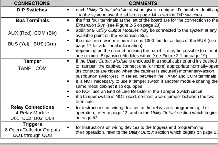
DIP Switches §§ each Utility Output Module must be given a unique I.D. number identifying it to the system; use the table on page 14 to set the DIP switches
Bus Terminals
AUX (Red) COM (Blk) BUS (Yel) BUS (Grn)
§ the first four terminals at the left of the board are for the connection to the Expansion Bus (see Figure 2-5 on page 23)
§ additional Utility Output Modules may be connected to the system at any available point on the Expansion Bus
§ the maximum wire run permitted is 1000 feet for all legs of the BUS (see page 17 for additional information)
§ depending on the cabinet housing the panel, it may be possible to mount one or more Expansion Modules within (see Figure 2-1 on page 19)
Tamper
TAMP COM
§ if the Utility Output Module is enclosed in a metal cabinet and it’s desired to "tamper" the cabinet, connect one (or more) appropriate normally-open (its contacts are closed when the cabinet is secured) momentary-action pushbutton switch(es), in series, between the TAMP and COM terminals
§ it is NOT necessary to use a tamper switch if another module sharing the same metal cabinet if so equipped
§ do NOT use an End-of-Line Resistor in the Tamper Switch circuit
§ if a tamper switch is NOT used, connect a wire jumper between the two terminals
Relay Connections
4 Relay Module U01 U02 U03 U04
§ for instructions on wiring devices to the relays and programming their operation, refer to page 13, and to the Utility Output section which begins on page 63
Triggers
8 Open-Collector Outputs UO1 through UO8
§ for instructions on wiring devices to the triggers and programming
their operation, refer to the Utility Output section which begins on page 63
O
O
t
t
h
h
e
e
r
r
M
M
o
o
d
d
u
u
l
l
e
e
s
s
All other ORBIT-Pro modules not discussed in these pages are equipped with their own wiring and operating instructions.
W
W
i
i
r
r
i
i
n
n
g
g
G
G
u
u
i
i
d
d
e
e
l
l
i
i
n
n
e
e
s
s
One of the necessary factors required in making for a successful installation is the proper use of wire and cable. Like all hardwired security systems, the ORBIT-Pro relies on wire to carry power and data to the Keypads, Expansion Modules, detectors, and any external sounder(s) which may be part of the installation. If the wire is too long or not thick enough for the quantity and types of components in use, excessive voltage drops could develop and deprive such devices of sufficient power–resulting in unreliable system operation and weak-sounding annunciators.
A
A
W
W
o
o
r
r
d
d
A
A
b
b
o
o
u
u
t
t
W
W
i
i
r
r
e
e
If the proper wire thicknesses are selected before beginning, power losses can be minimized. By taking into account an installation’s current requirements and the wiring distances involved, Tables 2-2 through 2-5 provides useful information to help make your installation trouble-free.
Table 2-1 is offered for reference. As it indicates, a wire’s diameter is assigned a numeric size, or gauge–a number which is based on AWG (American Wire Gauge) designations. Note that as a wire’s diameter increases, however, its AWG size gets numerically lower.
Wire Diameter Resistance: Feet Resistance: Meters
AWG Gauge
Size Inches millimeters Ω per foot Ω per 1000 ft Ω per meter Ω per 100 m
24 0.020 0.50 0.026 26.0 0.085 8.5 22 0.025 0.64 0.016 16.0 0.052 5.2 20 0.031 0.80 0.010 10.0 0.032 3.2 19 0.035 0.90 0.008 8.0 0.026 2.6 18 0.040 1.00 0.006 6.0 0.020 2.0 16 0.050 1.27 0.004 4.0 0.013 1.3 14 0.064 1.63 0.0025 2.5 0.008 0.82
Table 2-1: Wire Facts
One-Way Wire Distance Between ORBIT-Pro and Plug-In Transformer
AWG (American Wire Gauge)
for best results use the indicated wire size or larger (numerically lower) size
in feet in meters 22 20 18 16 14 up to 15 ft up to 5 m 4 15 – 25 ft 5 – 8 m 4 25 – 40 ft 8 – 12 m 4 40 – 60 ft 12 – 20 m 4 60 – 100 ft 20 – 30 m 4
Table 2-2: Wiring Between the ORBIT-Pro Main Board and the 16.5VAC / 40VA Plug-In Transformer Maximum Combined Length
of All Expansion BUS Wiring Wire Gauge (AWG) Size in feet in meters 22 656 200 20 1092 333 19 1312 400
Table 2-3: 4-Wire Expansion BUS Wiring One-Way Lengths Based on Wire Gauge NOTE: For maximum system stability, it is best NOT to exceed a total of 1000 feet of wire when wiring the Expansion BUS.
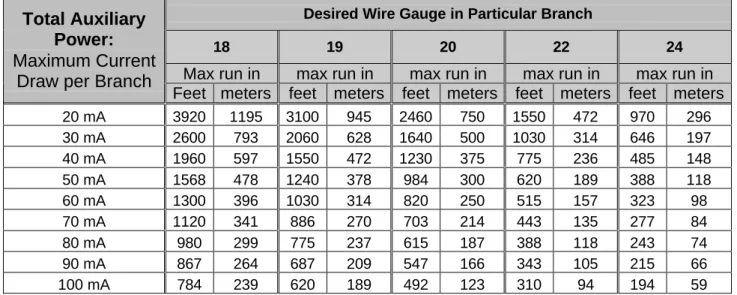
Desired Wire Gauge in Particular Branch
18 19 20 22 24
Max run in max run in max run in max run in max run in
Total Auxiliary
Power:
Maximum Current
Draw per Branch
Feet meters feet meters feet meters feet meters feet meters
20 mA 3920 1195 3100 945 2460 750 1550 472 970 296 30 mA 2600 793 2060 628 1640 500 1030 314 646 197 40 mA 1960 597 1550 472 1230 375 775 236 485 148 50 mA 1568 478 1240 378 984 300 620 189 388 118 60 mA 1300 396 1030 314 820 250 515 157 323 98 70 mA 1120 341 886 270 703 214 443 135 277 84 80 mA 980 299 775 237 615 187 388 118 243 74 90 mA 867 264 687 209 547 166 343 105 215 66 100 mA 784 239 620 189 492 123 310 94 194 59
Table 2-4: Auxiliary Power Branch Wiring Lengths Based on Gauge Sizes and Detector Current NOTE: The wire lengths indicated represent the one-way distance between the source of power and the last
detector in the branch.
Desired Wire Gauge in Particular Branch
18 19 20 22
max run in max run in max run in max run in
Maximum External Sounder Current:
Maximum Current Draw per Branch
feet meters feet meters feet meters feet meters
100 mA 780 238 625 191 495 151 310 94 200 mA 390 119 313 95 248 76 155 47 300 mA 260 79 208 63 165 50 103 31 400 mA 195 59 157 48 124 38 78 24 500 mA 156 48 125 38 99 30 62 19 650 mA 120 37 96 29 76 23 48 15
Table 2-5: External Sounder Wiring Table
NOTE: The wire lengths indicated represent the one-way distance between the ORBIT-Pro and the external sounder in the branch.
Zone Terminations
Figure 2-4Wiring Diagram
Figure 2-7Section 3: Programming Your ORBIT-Pro
S
S
u
u
m
m
m
m
a
a
r
r
y
y
o
o
f
f
I
I
n
n
s
s
t
t
a
a
l
l
l
l
e
e
r
r
P
P
r
r
o
o
g
g
r
r
a
a
m
m
m
m
i
i
n
n
g
g
M
M
e
e
t
t
h
h
o
o
d
d
s
s
As a source of general reference, the following table lists the options available when programming an ORBIT-Pro installation. Except for this reference, this section will concern itself only with such programming from an LCD Keypad only.
PROGRAMMING METHODS
LOCALLY (at the panel) REQUIREMENTS
• from any LCD Keypad (covered in this manual)
• the keypad must be DIP switch programmed and wired to the ORBIT-Pro
• power must be applied to the ORBIT-Pro
• from a portable computer
• see the Upload/Download Programming Manual (p/n 5IN296UD) for additional information
• the PC must be IBM®-compatible
• Rokonet's Upload/Download Software (p/n RP296UD) must be installed
• the Bus Adapter (p/n RP296BA) cable and plug must be connected between a serial (COM) port on the PC and the ORBIT-Pro’s “J1” connector–or the equivalent connection * on the 4-wire BUS
• via the Program Transfer Module (p/n RP296EE), a tiny circuit board into which a copy of a panel’s programmed configuration is stored–from which it may later be transferred to any installation when temporarily plugged into its 4-wire bus
• see page 112 for detailed instructions) on the use of the Program Transfer Module
• the Program Transfer Module (p/n RP296EE) *
REMOTELY (at the alarm company) REQUIREMENTS
• from a personal computer
• see the Upload/Download Programming Manual (p/n 5IN296UD) for additional information)
• the PC must be IBM®-compatible
• Rokonet's Upload/Download Software (p/n RP296UD) must be installed an applicable modem must be installed and configured access to a telephone line
*
Table 3-1 * Not for UL Installations
P
P
r
r
e
e
p
p
a
a
r
r
i
i
n
n
g
g
Y
Y
o
o
u
u
r
r
O
O
R
R
B
B
I
I
T
T
-
-
P
P
r
r
o
o
f
f
o
o
r
r
I
I
n
n
s
s
t
t
a
a
l
l
l
l
e
e
r
r
P
P
r
r
o
o
g
g
r
r
a
a
m
m
m
m
i
i
n
n
g
g
There are three “Getting Started” options when learning how to program your ORBIT-Pro. OPTION 1: You wish to program a new ORBIT-Pro for the first time.
OPTION 2: You wish to restore all factory defaults to an already-programmed ORBIT-Pro. OPTION 3: You wish to modify the configuration of an existing ORBIT-Pro. For this, proceed
directly to one of the following pages:
Description and Use of the LCD Keypad page 30 Installer Programming Tutorial page 35
Actual Programming page 39
For Options 1 and 2
A. Preparing the LCD Keypad:
1- Remove all Power from Your ORBIT-Pro
a) If your ORBIT-Pro has NOT been wired to an LCD Keypad, remove all power (AC and Standby Battery) if present, and skip to Step 2.
b) If your ORBIT-Pro and at least one LCD Keypad have already been physically installed and/or wired together, remove all power (AC and Standby Battery) if present, and skip to Step 3.
2- Wire a single LCD Keypad to the ORBIT-Pro’s Main Board
a)
If required, add additional wiring to the keypad, by using no more than 1000 feet of the appropriate wire.3- If necessary, check the LCD Keypad’s Physical I.D. Number
If the LCD Keypad(s) have already been given an I.D. number, skip to Step 5. Otherwise, separate the keypad’s cover from its base, locate the bank of four DIP switches and make sure the keypad is given the I.D. of “01”, by verifying that all four switches are in the down (OFF) position
4- Reassemble the Keypad
Carefully replace the keypad’s printed circuit board in its cover housing
join the unit’s cover and base by first hooking the tops together and then snapping the bottoms in place 5- Setting the Keypad’s Tamper Switch
If the keypad is not yet mounted, locate its rear-mounted tamper “plunger” and set its action as follows:
a)
if, during programming, the keypad is to be wall-mounted, be sure the slot in the plunger is vertically-oriented, and reinstall the keypadb)
otherwise, for bench, table-top, or “hand-held” programming, turn the plunger so that its slot is horizontally-orientedB. Preparing the Panel: (refer to Figure 2-7 on page 25)
6- Check the Condition of the ORBIT-Pro’s J2 (DEFAULT) JumperOption 1: If you are Programming a New ORBIT-Pro:
a) Be sure the jumper is NOT placed over its corresponding pins. You may wish to place it on one of the pins for safekeeping.
b) Proceed to Step 7.
Option 2: If you are Restoring Factory Defaults to an ORBIT-Pro:
a) Place the jumper in the DEFAULT position so it covers BOTH of the corresponding pins. b) Proceed to Step 7.
7- Apply Power to the System
Do so by plugging in the AC transformer, and/or connecting the Standby Battery to the RED and BLACK flying leads. After a moment, the keypad will display:
ROKONET
Please Wait ...
C. Initial Programming:
8- Observe the Following and Perform these Initial Steps
a) After about 20 seconds, the keypad will produce either of the two displays below. Follow the instructions in the column which is applicable to what is displayed:
If this display appears, follow the instructions in this column:
If this display appears, follow the instructions in this column:
b) press the [QQ] key; the keypad will display:
c) carefully enter the ORBIT-Pro’s default Installer Code: [ 0 ] [ 2 ] [ 9 ] [ 6 ] (which will appear as
QQQQ) and press [ENTER] d) the keypad briefly displays:
and then, this display:
b) Above, the term “PARTITION 1” represents the name given to a previously-programmed ORBIT-Pro, or to one of its partitions. Its appearance, rather than the display at the upper left, indicates that this ORBIT-Pro has:
• already been programmed
• protected the programmed configuration
• disabled your ability to restore the factory defaults To enable your ability to restore the factory defaults, follow the steps below:
c) press [QQ], then [7], then [1]
•
note that the POWER LED will be flashing slowly,indicating that the Programming Mode has been entered
e) next, you must program the system to recognize the keypad; to do so, press [7]; the display will show:
(Note: MDL=Module)
press the [ENTER] key; the keypad displays:
d) at this display:
• enter this ORBIT-Pro’s current Installer Code; note that this must be the Installer Code assigned to this panel when it was last in service
• if the ORBIT-Pro’s factory default Installer Code was retained during the panel’s previous use, enter [0] [2] [9] [6] (which will appear as QQQQQQQQ) and press [ENTER]
f) press [ENTER] again; the display shows:
g)change the keypad’s TYPE to LCD by pressing the [STAY] key until TYPE=LCD appears in the lower right of the display
e) the keypad briefly displays:
and then, at this display:
press [ENTER], followed by [7]
PARTITION 1
--:-- ... .. ...
INSTALLER CODE:
_
ROKONET
Please Wait ...
PARTITION 1
--:-- ... .. ...
INSTALLATION:
PLEASE, WAIT
INSTALLER PROG:
1)SYSTEM
↓↓
INSTALLATION:
PLEASE, WAIT
INSTALLER PROG:
1)SYSTEM
↓↓
INSTALLER CODE:
_
ACCESSORIES:
1)ADD/DEL MDL
↓↓
ADD A MODULE:
1)KEYPAD
↓↓
KEYPADS:
ID=01 TYPE=NONE
To Install
Press
Q
Q
h) press the [ENTER] key; the resulting display confirms the following information about the keypad:
• it has been given the I.D. of “01” (which matches the keypad’s DIP switch settings
• it has been assigned to Partition 1 (the only partition in the system, thus far)
f) at this display:
press the [STAY] key once so that the display reads:
and then press [ENTER]
g) remove the J2 DEFAULT jumper from its position on the Main Board, and place it over one of the two pins for safekeeping
h) press [QQ] and then [0]; the keypad displays i) save this information by pressing the [QQ] key four
times, followed by [0]; the keypad will then display:
j) press [ENTER] to confirm; the display shows:
and then, a few moments later:
i) press [ENTER]; the display shows:
and then, a few moments later:
k) after a moment, the system will enter its ordinary operating mode
j) when the ORBIT-Pro’s factory defaults have been restored, this display will appear
§ until the system’s TIME and DATE are set, the display will show hyphens and periods, respectively
§ “PARTITION 1” is the default designation given to the system at this time; during programming, it can be changed to give the installation a name (e.g. “The Jones’s”, “Elm Lumber”) in a non-partitioned system, or to identify a specific area (e.g. “Sales Dept”) in a partitioned system
9- Choose Among the Following Options: to end your initial
programming session now:
to wall-mount your keypad and
continue programming to continue programming
• remove power (both AC and Standby Battery) from your system until you’re ready to continue with Installer Programming
• the ORBIT-Pro will retain its programmed data
• when ready, proceed with Installer Programming below
• remove power (both AC
and Standby Battery) to avoid a tamper alarm
• locate the keypad’s tamper “plunger” and orient its slot vertically
• if desired, re-apply power after mounting the keypad; the above display will appear after a few seconds
• when ready, continue with Installer Programming below
• continue below