Guided W
ave
Radar-based
Level
Measurement
7xxx
6xxx
5xxx
4xxx
3xxx
2xxx
1xxx
Installation and Operating Manual
™
Size: 38 mm (1 1/2") or adjustable wrench
Customer supplied brackets are recommended per each 3 m length. (Required for WGH § 19 installations.)
Not important
min 25 mm (1") from tank bottom min. 1" - 150 lbs
DN 25 PN 16
3/4"
UNPACKING
Unpack the instrument carefully. Make sure all components have been removed from the foam protection. Inspect all components for damage. Report any concealed damage to the carrier within 24 hours. Check the contents of the car-ton/crates against the packing slip and report any discrep-ancies to Magnetrol. Check the nameplate model number (Model number/approvals as per inserted separate sheet) to be sure it agrees with the packing slip and purchase order. Check and record the serial number for future reference when ordering parts.
MOUNTING
These units are in conformity with the
provisions of:
1. The EMC Directive: 89/336/EEC. The units have been tested to EN 4/2001 and EN 61000-6-2/2001.
2. Directive 94/9/EC for Equipment or protective system for use in potentially explosive atmospheres. EC-type exam-ination certificate number KEMA99ATEX0518X (intrinsic safe units) or KEMA99ATEX5311 (EEx d units) or KEMA99ATEX5014 (Non sparking units).
3. The PED directive 97/23/EC (pressure equipment direc-tive). Safety accessories per category IV module H1.
Amplifier nameplate: - partnumber - amplifier - serial n° - temperature/pressure - approval data Probe nameplate - partnumber - serial number
7MA/7MD/7MR/7MS coaxial GWR probe 7MB Twin Rod GWR probe
min. 3" - 150 lbs DN 80 PN 16 2" Size: 47 mm (1 7/8") or adjustable wrench min. 25 mm (1") from any metal
object
min 25 mm (1") from tank bottom
0038 0344
Use half open brackets If nozzle is
< DN 80 (3"): inactive part needs to be min. flush with inside tankwall or inside vessel
MOUNTING
7MT interface Size: 38 mm (1 1/2") or adjustable wrenchCustomer supplied brackets are recommended per each 3 m length.
Not important
min 25 mm (1") from tank bottom min. 1" - 150 lbs
DN 25 PN 16 3/4"
MOUNTING CONSIDERATIONS
Turbulence
Nozzles: do not restrict the performance by ensuring the following:
For 7MF/7M1/7M2/7MJ
The bottom of the probe should be stabilized if turbulence
will cause a deflection of more than 75 mm at 3 m (3" at 10') of length. The probe should not make contact with a metal tank. A TFE bottom spacer for single rod GWR probes (7MF) or PEEK spacer for 7MJ is optional.
For 7MF/7M1/7M2/7MJ (single rod/cable):
1. Nozzle must be 50 mm (2") or larger diameter.
2. Nozzle inside diameter (A)should be ≥to nozzle height (B). If this is not the case, it is recommended to adjust
BLOCKING DISTANCE and/or DIELECTRIC/SENSI-TIVITY settings.
For 7M5/7M7 (twin rod/cable):
1. Nozzle should be DN80 (3") diameter or larger.
2. For nozzles < DN80 (3") diameter, the bottom of the inactive section of the probe should be flush with the bottom of the nozzle or extend into the vessel.
Metallic (conductive) obstructions in tank
For 7MF/7M1/7M2 (single rod/cable)
A metal stillwell/cage of max. 6"/DN size or a metal tank wall within 150 mm of the probe mounting will allow the unit operate accurately in media with dielectrics down to
εr
1,9. Objects in the proximity can cause erroneous readingsFor 7M5/7M7 (twin rod/cable)
Mount the probe more than 25 mm (1") from any metallic object/vesselwall.
Metallic obstructions
For 7MF/7M1/7M2 (single rod/cable)
1. Flange (metal) mounting is recommended for optimum performance.
Non-metallic vessels
Pipe reducers should not be used Correct installation
A B
Note: mounting considerations for 7M5/7M7 (Twin lead) GWR probes are minimal:
- keep a min spacing of 25 mm (1") between tank wall and any metal part of the tank (wall, pipes, support beams etc...) - mounting inside external cage/stillwell – min size should be 3"/DN 80
- for 7MF/7M1/7M2 probe can be attached to the tank bottom using the noose or the 13 mm (0.50") Ø hole provided in the TFE weight. Cable tension should not exceed 9 kg (20 lbs).
Distance to probe Acceptable objects
< 150 mm (6")
Continuous, smooth, parallel, con-ductive surface (e.g. metal tank wall); probe should not touch tank wall
> 150 mm (6") < 1"/DN25 diameter pipe and beams, ladder rungs
> 300 mm (12") < 3"/DN80 diameter pipe and beams, concrete walls > 450 mm (18") All remaining objects
MOUNTING
7MF/7MJ single rod GWR probe 7M1/7M2/7M5/7M7 flexible GWR probe
Size: 38 mm (1 1/2") or adjustable wrench min. 2" - 150 lbs DN 25 PN 16 2" Size: 38 mm (1 1/2") or adjustable wrench 13 mm Ø (0.50")
For twin cable: min 25 mm (1") from any metal object If nozzle is
< DN 80 (3"): inactive part needs to be min. flush with inside tankwall or inside vessel
min. 2" - 150 lbs DN 25 PN 16 2"
Probe can be stabilized by placing into a non-metallic cup or bracket at the bottom of the probe. A TFE, bottom spacer (P/N 089-9114-001) is optional for mounting into a metallic cup or bracket. 13 mm fl (0.50") 1 2 3 4 1 3 2 4
7M1/7M2 probe can be shortened in field.
a.raise TFE weight (1) exposing secur-ing device (2)
b. loosen both #10-32 set screws (3) using 2.5 mm (3/32") hex wrench and remove securing device c. cut and remove needed cable length
(4)
d. re-attach securing device (2) and tighten screws
e. enter new probe length (cm or inch-es) in software (See page 6, Item 8)
7M7/7M5 probe can be shortened in field.
a.raise The weight (1) to expose the two securing devices (2)
b. loosen the two #10-32 set screws (3) on both securing devices using a 2.5 mm (3/32") hex wrench and slide the securing devices off of the probe c. slide the TFE weight off of the probe. d. cut and remove the required cable (4)
length
e. remove 90 mm (3 1/2") of the rib between the two cables
f. strip 16 mm (5/8") of coating from the two cables.
g. slide the TFE weight back on to the probe.
h. enter new probe length (cm or inches) in software (See page 6, Item 8)
Note: Probe can be attached to the tank bottom using the noose or
the 13 mm Ø (0.50") hole provided in the TFE weight.
7M1/7M7 GWR probes: cable tension should not exceed 89 N (20 lbs).
7M2/7M5 GWR probes: pull down force should not exceed 1360 kg (3000 lbs)
13 mm Ø (0.50")
Do not insulate the high frequency connector in case of high temperature
applications Top/Bottom GWR probe
Insulation
WRONG GOOD
Max +150 °C (+300 °F)
Max +100 °C (+212 °F) for EEx d unit Eclipse Guided Wave Radar Transmitter
in Top/Bottom Configuration Typical Torque Tube Transmitter
in Top/Bottom Configuration
In addition to Magnetrol’s Torque Tube Cage Flange options, the Eclipse® 705 transmitter and 7EK GWR
probe/cage can also be used in replacing existing Top/Bottom and Top/Side torque tube installations. After removal of the existing torque tube cage assembly (transmitter, controller, and cage), Eclipse Guided Wave
Radar may then be installed directly in its place. Several models are available for some of the major torque tube dis-placer transmitter manufacturers. Because the Model 7EK probe/cage mounting dimensions and measuring ranges match the original manufacturer’s specification, no re-pip-ing is necessary.
Before
After
360° rotatable: Position for optimum wiring/viewing Max. rotation 270° Size: 38 mm (1 1/2") or Transmitter Integral Remote
On high or low temperature applications, install a vented
WIRING
CAUTION: power must be switched OFF before wiring the unit.
–+ IS ® – LOOP CURRENT IS 0 % 100 %
Positive supply to (+) terminal/HART connection Negative supply to (-) terminal/HART connection min. 11 V DC required – max 36 V DC
min. 9 V DC required for Foundation Fieldbus®.
Shield wire to green grounding screw (resistance to ground must be < 1 Ω).
Standard shielded twisted pair cable (recommended but not needed when wired as per NAMUR NE 21 for field strenghts up to 10 V/m).
Use certified flameproof cable gland(s) and cable for Explosion proof area.
Current loop test point
Galvanic Barrier:
Intrinsically safe units: max 28,6 V DC @ 140 mA Foundation Fieldbus units: max 17,5 V DC @ 380 mA Not needed for General Purpose / explosion proof models.
ANALOG I/O or DIGITAL I/O (only for units with HART)
Customer supplied local current meter
Do not connect shield
Ex Non Ex Ex Non Ex Ex Non Ex IMPORTANT:
The shield wire should only be grounded at ONE side only. It is recommended to connect the shield to ground in the field (at the transmitter side - as shown above) but connecting in the control room is also allowed.
LOOP RESISTANCE
1200
1000 20 mA
CONFIGURATION USING FOUNDATION FIELDBUS
® WIRINGUnlike 4–20mA analog installations in which the two wires carry a single variable (the varying 4–20 mA current), a dig-ital communications scheme such as Fieldbus considers the two wires as a network. The network can carry many process variables as well as other information. The Eclipse Model 705FF transmitter is a Foundation Fieldbus regis-tered device that communicates with the H1 Foundation Fieldbus protocol operating at 31.25 kbits/sec. The H1 physical layer is an approved IEC 61158 standard. The figure shows a typical Fieldbus installation.
An IEC61158 shielded twisted pair wire segment can be as long as 1900 meters (6234 feet) without a repeater. Up to 4 repeaters per segment can be used to extend the dis-tance. The maximum number of devices allowed on a Fieldbus segment is 32 although this depends on the cur-rent draw of the devices on any given segment.
Details regarding cable specifications, grounding, termina-tion, and other network information can be found in IEC 61158 or at www.fieldbus.org.
DEVICE CONFIGURATION Device Descriptions
The function of a Fieldbus device is determined by the
arrangement of a system of blocks defined by the Fieldbus Foundation. The types of blocks used in a typical User Application are described as follows:
Resource Block describes the characteristics of the
Fieldbus device such as the device name, manufacturer, and serial number.
Function Blocks are built into the Fieldbus devices as
needed to provide the desired control system behavior. The input and output parameters of function blocks can be linked over the Fieldbus. There can be numerous function blocks in a single User Application.
Transducer Blockscontain information such as calibration
date and sensor type. They are used to connect the sensor to the input function blocks.
An important requirement of Fieldbus devices is the inter-operability concept mentioned above. Device Description (DD) technology is used to achieve this interoperability. The
INTRINSICALLY SAFE
H1 supports Intrinsic Safety (IS) applications with bus
powered devices. To accomplish this, an IS barrier is placed between the power supply in the safe area and the device in the hazardous area.
H1 also supports the Fieldbus Intrinsically Safe Concept (FISCO) model which allows more field devices in a network. The FISCO model considers the capacitance and inductance of the wiring to be distributed along its entire length. The stored energy during a fault will be less and more devices are permitted on a pair of wires. Instead of the conservative entity model, which only allows about 90 mA of current, the FISCO model allows a maximum of 110 mA for Class II C installations and 240 mA for Class II B installa-tions.
FISCO certifying agencies have limited the maximum segment length to 1000 meters because the FISCO model does not rely on standardized ignition curves.
The Eclipse Model 705 is available with an entity IS, FISCO IS, and explosion proof approvals.
1900 meters (6234 ft) maximum Terminator Terminator PC Power Conditioner Power Supply Control Room
Typical Fieldbus Installation
NOTE: All Foundation Fieldbus devices must be tested for interoperability by the Fieldbus Foundation. Magnetrol Model 705FF device registration information can be found at www.fieldbus.org.
Display
Comment
Units!
cm
Units
cm
Units!
cm
CONFIGURATION
NOTE: When connected to an approved barrier, the intrinsically safe electronics of the Eclipse allow to remove the covers with power switched on – even if the area is known to be hazardous
2 line – 8 characters LCD
Default display cycles every 5 s through Status «STATUS» / Level «LEVEL»
/ % output «% OUTPUT» / Loop «LOOP». Level not displayd for FF units.
Up/Down and Enter pushbuttons
IMPORTANT: The Eclipse amplifier can be bench configured without GWR probe connected. Ignore the start up message «No Level Signal» /
«STATUS» / «WeakSgnl» in this case.
Press : The last character on the first line of the display changes to «!». This sign con -firms that the values/choices of the second line can be modified via the and push buttons.
Press * Scroll through the choices or increase/decrease the values on the second line of the display by and pushbuttons.
* Accept values/choices as selected by pushbutton.
Press Scroll through the menu.
PASSWORD
DISPLAY
ACTION/
COMMENT/
Ent Pass
0
Ent Pass!
1
Display shows «0» Factory default setting
Data is not protected
Press and last character changes into «!»
Enter your personal password with and (any value between 1 and 255)
Press to confirm
20 mA Level (100%-point) Reference point Probe Type Probe Length Offset Inch or cm Dielectric of medium Blocking distance 4 mA Level (0%-point) TERMINOLOGY BEFORE STARTING Offset = cm or inches
The offset is the distance between reference point (e.g. bottom of tank) and end of probe. From the reference point both 4 mA and 20 mA levels are calibrated. When offset is set at zero, the end of the probe is the reference point. 4 mA Level = cm or inches
or zero level point, is measured from the reference point. The unit has a transition zone at the bottom of the probe. Min. level to enter for media with:
ε
r = 2.0: 150 mm (6") + Offsetε
r = 80: 25 mm (1") + Offset20 mA Level = cm or inches
or 100 % level point, is measured from the reference point. The unit has a transition zone at the top of the probe. Transition zone varies depending on probe type and media: see probe specifications page 16.
Probe length = cm or inches, record the exact probe length as printed on the nameplate: 705-xxxx-xxx / 7Mx-xxx-xxx Dielectric Select the dielectric scale of the media to measure:
1.4–1.7 or 1.7–3 or 3–10or 10–100. When the dielectric is
known, it will enhance the overall accuracy of the unit but select the dielectric scale ALWAYS to the lowest expected dielectricum.
CONFIGURATION
Start from run mode:
1. Select the desired language for configuration: English, French, German or Spanish in the language screen (32) «language». Scroll up for quickly reaching the language selection screen.
2. Define type of measurement:
a. Level only (pages 10 & 11) b. Level and Volume (pages 12 & 13) c. Interface only (pages 14 & 15) d. Interface and Volume (pages 16 & 17)
Scroll down until the screen reads «MeasType». The unit will now show only the applicable screens for the selected type
of measurement.
3. Scroll one screen down and select the applicable engineering unit in «LvlUnits», all configuration values will be entered in that engineering unit.
4. Move to the loop control screen «LoopCtrl», select the loop control in function of the type of measurement «MeasType» No offset (Offset at 0 cm) Positive offset (Offset at 10 cm) Negative offset (Offset at -15 cm) 75 cm 100 % 0 % 15 cm 10 cm 20 mA = 75 cm 4 mA = 15 cm 20 mA = 85 cm 4 mA = 25 cm 20 mA = 60 cm 4 mA = 0 cm
= Quick Start up
MENU: STEP BY STEP PROCEDURE – Eclipse 705: Level only
Screen
Action
Comment
Run mode
Configuration
1 2 3 4 7 10 12 13 16 17 *Status* *Level* *%Output* *Loop* Level xx.x %Output xx.x% Loop xx.xx mA 5 PrbModel (select) MeasType (select) 6 PrbMount (select) 9 Probe Ln xxx.x 8 LvlUnits (select) Lvl Ofst xxx.x 11 Dielctrc (Select) Senstvty xxx Loop Ctrl (Select) 14 Set 4mA xxx.x Damping xx sec 15 Set 20mA xxx.x Fault (Select)Transmitter Display Transmitter default values cycle every 5 seconds. Status «Status», Level «Level», % Output «% Output», and Loop «Loop».
Transmitter Display Transmitter displays level value in selected engineering units.
Transmitter Display Transmitter displays % Output measurement derived from 20 mA span.
Transmitter Display Transmitter displays Loop measurement (mA).
Selectthe type of probe Select as per the 3 first digits of the probe partnumber. The partnumber
is shown on the nameplate: e.g. 705-510A-A11/7MR-A230-218, select 7xR-x from the list.
Selectthe type of probe mounting.
Select NPT «NPT», BSP «BSP» or Flange «Flange». (consult
facto-ry when a «7xK» GWR probe is used)
Selectthe type of measurement Select level «Levl Only».
Selectunits for level cm «cm», m «m», inches «inches» or feet «feet».
Enterthe exact length of probe.
Enter as per the 3 last digits of the probe partnumber on the nameplate: - rigid probes, enter value cm or inches,
- flexible probes, enter value in meters or feet
e.g. 705-510A-A11/7MR-A230-280, enter «218» cm probe length.
Enterthe offset value. When entering configuration values from the end of the probe is
cumbersome, an offset can be introduced to determine a new reference point. This reference point can be either below the probe (positive offset) or at the probe (negative offset). See page 9 “Terminology”.
Enterthe dielectric range
value of the media
Select: «1.4–1.7»; «1.7–3» or «10–100»
Change cryptic value Probe length is printed on the nameplate and order information. It is the last three digits of the model number.
(consult factory when a «7xK» GWR probe is used)
Selectprimary variable (PV) Primary variable is the loop controlling parameter. Select level
«Lvl only»
Enterthe level value for the 4 mA point.
A transition zone may exist at the bottom of the probe. See Functional Specifications Probe, See pages 30, 31 and 32.
Enterthe levelvalue for the 20 mA point.
A transition zone / blocking distance may exist at the top of the probe. See Functional Specifications Probe See pages 30, 31 and 32.
Enterthe damping factor. A Damping factor (1-10 seconds) may be added to smooth a noisy
display and/or output due to turbulence.
Enterthe value for error. Select «3.6 mA», «22 mA» or hold last value «HOLD». In case of
loop failure, error signal will follow the failing trend; meaning the unit will show 3.6 mA when the reviewed loop current by the device is found too low. The unit will show 22 mA in case the reviewed loop current is found too high.
MENU: STEP BY STEP PROCEDURE – Eclipse 705: Level only
Screen
Action
Comment
Diagnostics
23 25 26 27 28 29 Poll Adr xx Trim 4 xxxx 24 Trim Lvl xx.x Trim 20 xxxx Loop Tst xx.x mA LvlTicks xxxxx New Pass xxx 30 31 Language Mdl705HT Ver xx.xx 32 DispFact (select) 18 19 20 21 22 BlockDis xx.x SZ Fault (select) SZHeight xx.x SZ Alarm Reset Threshld (select) Enterdistance in selected level unitsAllows to ignore level measurements near the top of the probe, caused by e.g. condensation, crystalization. Make sure that the liquid level does NOT enter this zone. Consult factory or the
‘Troubleshooting’ section before entering any value. Normaly to be used with single rod probe.
Select the safety zone fault. Select «None» (None), «3.6mA», «22mA», «Latch 3.6mA» or «Latch 22mA». When either «Latch 3.6 / 22mA» signals is selected, the loop current remains in alarm until it is manually cleared with the «SZAlarm» screen ( for safety zone explanation see Terminology - page 9).
Select the safety zone value Enter safety zone in cm or inches (see Terminology - page 9).
Reset safety zone latch fault Clear a latched safety zone alarm «SZFault».
Select the type of threshold Unit default CFD «CFD». Only select Fixed «Fixed» in application with low dielectric material over higher dielectric material and unit is reading incorrect level. Example: oil over water. Select Dielectric
Range «Dielctrc» of upper material. Adjustment of Trim Level
«Trim Lvl» may be necessary when threshold is changed. Enter HART ID number. Select a HART poll address (0-15). Enter 0 for a single transmitter
installation. Enter value
to adjust level reading.
Allows to compensate for a fixed level deviation.
Fine tune the 4 mA point. Attach a mA meter to the output. If the output does not equal 4.0 mA, adjust the value on the display to equal 4.00 mA.
Fine tune the 20 mA point. Attach a mA meter to the output. If the output does not equal 20.0 mA, adjust the value on the display to equal 20.00 mA. Enter a mA output value. Set mA Output to any given value to perform loop test .
Diagnostic display. Shows time of flight from fiducial pulse to reflected signal from level.
Enter new password. Use arrows to select desired value. Values between 0 and 255.
Select language Select «English», «Français», «Deutsch» or «Espagnol». None, do not adjust. Factory setting. «Ver» refers to software version.
Advanced diagnostics. See page 18.
No offset (Offset at 0 cm) Positive offset (Offset at 10 cm) Negative offset (Offset at -15 cm) 75 cm 100 % 0 % 15 cm 10 cm 20 mA = 75 cm 4 mA = 15 cm 20 mA = 85 cm 4 mA = 25 cm 20 mA = 60 cm 4 mA = 0 cm
= Quick Start up
MENU: STEP BY STEP PROCEDURE – Eclipse 705: Level & Volume
Screen
Action
Comment
Run mode
Configuration
1 2 3 4 8 11 12 13 19 20 *Status* *Volume* *%Output* *Loop* Volume xxx %Output xx.x% Loop xx.xx mA 5 Level xxx MeasType (select) 7 PrbMount (select) 6 PrbModel (select) 10 Probe Ln xxx.x 9 LvlUnits (select) Lvl Ofst xxx.x 14 Dielctrc (Select) VolUnits (select) StrapTbl xx pnts 17 Set 4mA xxx.x Damping xx sec 18 Set 20mA xxx.x 15 Senstvty xxx 16 Loop Ctrl (Select) Fault (Select)Transmitter Display Transmitter default values cycle every 5 seconds. Status «Status», Volume «Volume», % Output «% Output», and Loop «Loop».
Transmitter Display Transmitter displays Volume Value in selected engineering units.
Transmitter Display Transmitter displays % Output measurement derived from 20 mA span.
Transmitter Display Transmitter displays Loop measurement (mA).
Transmitter Display Transmitter displays level in selected volume units «LvlUnits».
Selectthe type of probe Select as per the 3 first digits of the probe partnumber. The partnumber
is shown on the nameplate: e.g. 705-510A-A11/7MR-A230-218, select 7xR-x from the list.
Selectthe type of probe mounting.
Select NPT «NPT», BSP «BSP» or Flange «Flange». (consult
facto-ry when a «7xK» GWR probe is used)
Selectthe type of measurement Select level and volume «Lvl&Vol».
Selectunits for level cm «cm», m «m», inches «inches» or feet «feet».
Enterthe exact length of probe.
Enter as per the 3 last digits of the probe partnumber on the nameplate: - rigid probes, enter value cm or inches,
- flexible probes, enter value in meters or feet
e.g. 705-510A-A11/7MR-A230-280, enter «218» cm probe length.
Enterthe offset value. When entering configuration values from the end of the probe is
cumbersome, an offset can be introduced to determine a new reference point. This reference point can be either below the probe (positive offset) or at the probe (negative offset). See page 9 “Terminology”.
Selectunits for volume Liters «l» or gallons «g».
Enterlevel/volume pairs in max 20 steps
Liters «l» or gallons «g».
Enterthe dielectric range
value of the media
Select: «1.4–1.7»; «1.7–3» or «10–100»
Entersensitivity value Enter a value upward or downward to sense the liquid surface. Allows fine gain adjustment.
Selectprimary variable (PV) Primary variable is the loop controlling parameter. Select level
«Lvl only»
Enterthe level value for the 4 mA point.
A transition zone may exist at the bottom of the probe. See Functional Specifications Probe, See page XX.
Enterthe levelvalue for the 20 mA point.
A transition zone / blocking distance may exist at the top of the probe. See Functional Specifications Probe See page XX.
Enterthe damping factor. A Damping factor (1-10 seconds) may be added to smooth a noisy
display and/or output due to turbulence.
Enterthe value for error. Select «3.6 mA», «22 mA» or hold last value «HOLD». In case of
loop failure, error signal will follow the failing trend; meaning the unit will show 3.6 mA when the reviewed loop current by the device is found too low. The unit will show 22 mA in case the reviewed loop current is found too high.
MENU: STEP BY STEP PROCEDURE – Eclipse 705: Level & Volume
Screen
Action
Comment
Diagnostics
26 28 29 30 31 32 Poll Adr xx Trim 4 xxxx 27 Trim Lvl xx.x Trim 20 xxxx Loop Tst xx.x mA LvlTicks xxxxx New Pass xxx 33 34 Language Mdl705HT Ver xx.xx 21 22 23 24 25 BlockDis x.x SZ Fault (select) SZHeight xx.x SZ Alarm Reset Threshld (select) Enterdistance in selected level unitsAllows to ignore level measurements near the top of the probe, caused by e.g. condensation, crystalization. Make sure that the liquid level does NOT enter this zone. Consult factory or the
‘Troubleshooting’ section before entering any value. Normaly to be used with single rod probe.
Select the safety zone fault. Select «None» (None), «3.6mA», «22mA», «Latch 3.6mA» or «Latch 22mA». When either «Latch 3.6 / 22mA» signals is selected, the loop current remains in alarm until it is manually cleared with the «SZAlarm» screen ( for safety zone explanation see Terminology - page 9).
Select the safety zone value Enter safety zone in cm or inches (see Terminology - page 9).
Reset safety zone latch fault Select «Reset» «No» or «Yes» to reset alam when either «Latch
3.6mA» or «Latch 22mA» was selected in «SZFault».
Select the type of threshold Unit default CFD «CFD». Only select Fixed «Fixed» in application with low dielectric material over higher dielectric material and unit is reading incorrect level. Example: oil over water. Select Dielectric
Range «Dielctrc» of upper material. Adjustment of Trim Level
«Trim Lvl» may be necessary when threshold is changed. Enter HART ID number. Select a HART poll address (0-15). Enter 0 for a single transmitter
installation. Enter value
to adjust level reading.
Allows to compensate for a fixed level deviation.
Fine tune the 4 mA point. Attach a mA meter to the output. If the output does not equal 4.0 mA, adjust the value on the display to equal 4.00 mA.
Fine tune the 20 mA point. Attach a mA meter to the output. If the output does not equal 20.0 mA, adjust the value on the display to equal 20.00 mA. Enter a mA output value. Set mA Output to any given value to perform loop test .
Diagnostic display. Shows time of flight from fiducial pulse to reflected signal from level.
Enter new password. Use arrows to select desired value. Values between 0 and 255.
Select language Select «English», «Français», «Deutsch» or «Espagnol». None, do not adjust. Factory setting. «Ver» refers to software version.
Advanced diagnostics. See page 18.
Strapping table max. Pt 20 Lvl = ... cm Pt 4 Lvl = 200 cm Pt 3 Lvl = 120 cm Pt 2 Lvl = 50 cm Pt 1 Lvl = 0 cm max. Pt 20 Vol = ... l Pt 4 Vol = 3000 l Pt 3 Vol = 2000 l Pt 2 Vol = 1000 l Pt 1 Vol = 0 l 35 DispFact (select)
= Quick Start up
MENU: STEP BY STEP PROCEDURE – Eclipse 705: Interface
Screen
Action
Comment
Run mode
Configuration
1 2 3 4 8 11 12 15 18 19 *Status* *IfcLevel* *%Output* *Loop* IfcLevel xx.x %Output xx.x% Loop xx.xx mA 5 Level xxx MeasType (select) 7 PrbMount (select) 6 PrbModel (select) 10 Probe Ln xxx.x 9 LvlUnits (select) Lvl Ofst xxx.x 13 Dielctrc (Select) 14 Senstvty xxx Upr Diel (Select) Loop Ctrl (Select) 16 Set 4mA xxx.x Damping xx sec 17 Set 20mA xxx.x Fault (Select)Transmitter Display Transmitter default values cycle every 5 seconds. Status «Status», Interface level «Ifclevel», % Output «% Output», and Loop «Loop».
Transmitter Display Transmitter displays interface level in selected engineering units.
Transmitter Display Transmitter displays % Output measurement derived from 20 mA span.
Transmitter Display Transmitter displays Loop measurement (mA).
Transmitter Display Transmitter displays interface level in selected level units «LvlUnits».
Selectthe type of probe Select as per the 3 first digits of the probe partnumber. The partnumber
is shown on the nameplate: e.g. 705-510A-A11/7MR-A230-218, select 7xR-x from the list.
Selectthe type of probe mounting.
Select NPT «NPT», BSP «BSP» or Flange «Flange». (consult
facto-ry when a «7xK» GWR probe is used)
Selectthe type of measurement Select interface «Interface».
Selectunits for level cm «cm», m «m», inches «inches» or feet «feet».
Enterthe exact length of probe.
Enter as per the 3 last digits of the probe partnumber on the nameplate: - rigid probes, enter value cm or inches,
- flexible probes, enter value in meters or feet
e.g. 705-510A-A11/7MR-A230-280, enter «218» cm probe length.
Enterthe offset value. When entering configuration values from the end of the probe is
cumbersome, an offset can be introduced to determine a new reference point. This reference point can be either below the probe (positive offset) or at the probe (negative offset). See page 9 “Terminology”.
Enterthe dielectric range value of the upper media.
Enter the dielectrics of the upper layer liquid (between 1,4 and 5,0) – only upper layer dielectrics need to be entered.
Selectthe dielectric range
value of the lower media
Select: «10–100»
Entersensitivity value Enter a value upward or downward to sense the liquid surface. Allows fine gain adjustment.
Selectprimary variable (PV) Primary variable is the loop controlling parameter. Select
inter-face level «Ifc Level» only
Enterthe level value for the 4 mA point.
A transition zone may exist at the bottom of the probe. See Functional Specifications Probe, See pages 30, 31 and 32.
Enterthe levelvalue for the 20 mA point.
A transition zone / blocking distance may exist at the top of the probe. See Functional Specifications Probe See pages 30, 31 and 32.
Enterthe damping factor. A Damping factor (1-10 seconds) may be added to smooth a noisy
display and/or output due to turbulence.
Enterthe value for error. Select «3.6 mA», «22 mA» or hold last value «HOLD». In case of
loop failure, error signal will follow the failing trend; meaning the unit will show 3.6 mA when the reviewed loop current by the device is found too low. The unit will show 22 mA in case the reviewed loop current is found too high.
MENU: STEP BY STEP PROCEDURE – Eclipse 705: Interface
Screen
Action
Comment
Diagnostics
26 25 29 30 31 34 Poll Adr xx IfcThrs (select) 24 Threshld Trim 20 xxxx Loop Tst xx.x mA 27 28 Trim Lvl xx.x Trim 4 xxxx LvlTicks xxxxx New Pass xxx 35 36 Language Mdl705HT Ver xx.xx 32 33 IfcTicks xxxx Medium 20 21 22 23 BlockDis x.x SZ Fault (select) SZHeight xx.x SZ Alarm Reset Enterdistance in selected level unitsAllows to ignore level measurements near the top of the probe, caused by e.g. condensation, crystalization. Make sure that the liquid level does NOT enter this zone. Consult factory or the
‘Troubleshooting’ section before entering any value. Normaly to be used with single rod probe.
Select the safety zone fault. Select «None» (None), «3.6mA», «22mA», «Latch 3.6mA» or «Latch 22mA». When either «Latch 3.6 / 22mA» signals is selected, the loop current remains in alarm until it is manually cleared with the «SZAlarm» screen ( for safety zone explanation see Terminology - page 9).
Select the safety zone value Enter safety zone in cm or inches (see Terminology - page 9).
Reset safety zone latch fault Clear a latched safety zone alarm «SZFault».
Select top level threshold. Default selection is «Fixed». For most common applications.
Select interface threshold. Default selection is «CFD», in case the unit does not track the correct interface layer, select «Fixed». For most common applications. Enter HART ID number. Select a HART poll address (0-15). Enter 0 for a single transmitter
installation. Enter value
to adjust level reading.
Allows to compensate for a fixed level deviation.
Fine tune the 4 mA point. Attach a mA meter to the output. If the output does not equal 4.0 mA, adjust the value on the display to equal 4.00 mA.
Fine tune the 20 mA point. Attach a mA meter to the output. If the output does not equal 20.0 mA, adjust the value on the display to equal 20.00 mA. Enter a mA output value. Set mA Output to any given value to perform loop test .
Diagnostic display. Shows time of flight from fiducial pulse to reflected signal from level.
Diagnostic display. Shows time of flight through the upper liquid layer.
Diagnostic display. Shows type of detected upper liquid; unknown «Unknown» oil only «Oil Only», thin oil layer «Thin Oil» or no level «Dry Probe». Enter new password. Use arrows to select desired value. Values between 0 and 255.
Select language Select «English», «Français», «Deutsch» or «Espagnol». None, do not adjust. Factory setting. «Ver» refers to software version.
Advanced diagnostics. See page 18.
37 DispFact (select) No offset (Offset at 0 cm) Positive offset (Offset at 10 cm) Negative offset (Offset at -15 cm) 75 cm 100 % 20 mA = 75 cm 20 mA = 85 cm 20 mA = 60 cm
MENU: STEP BY STEP PROCEDURE – Eclipse 705: Interface & Volume
Screen
Action
Comment
Run mode
Configuration
1 2 3 4 7 13 16 19 22 *Status* *IfcVol* *%Output* *Loop* IfcLevel or Ifc Vol %Output xx.x% Loop xx.xx mA 6 Volume xx.x Level xxxx 5 IfcLvl xxxx 12 Probe Ln xxx.x 11 LvlUnits (select) Lvl Ofst xxx.x 17 Dielctrc (Select) Upr Diel (Select) Loop Ctrl (Select) 14 VolUnits Damping xx sec 15 StrapTbl xx pntsTransmitter Display Transmitter default values cycle every 5 seconds. Status «Status», Interface volume «IfcVolume», % Output «% Output», and Loop «Loop».
Transmitter Display Transmitter displays Interface volume or Interface level in selected engineering units (depending selection in Loop control «Loop Ctrl» Transmitter Display Transmitter displays % Output measurement derived from 20 mA
span.
Transmitter Display Transmitter displays Loop measurement (mA).
Transmitter Display Transmitter displays interface level in selected level units «LvlUnits».
Transmitter Display Transmitter displays volume in selected volume units «VollUnits».
Transmitter Display Transmitter displays level in selected level units «LvlUnits».
Selectthe type of probe Select as per the 3 first digits of the probe partnumber. The partnumber
is shown on the nameplate: e.g. 705-510A-A11/7MR-A230-218, select 7xR-x from the list.
Selectthe type of probe mounting.
Select NPT «NPT», BSP «BSP» or Flange «Flange». (consult
facto-ry when a «7xK» GWR probe is used)
Selectthe type of measurement Select level «Levl Only».
Selectunits for level cm «cm», m «m», inches «inches» or feet «feet».
Enterthe exact length of probe.
Enter as per the 3 last digits of the probe partnumber on the nameplate: - rigid probes, enter value cm or inches,
- flexible probes, enter value in meters or feet
e.g. 705-510A-A11/7MR-A230-280, enter «218» cm probe length.
Enterthe offset value. When entering configuration values from the end of the probe is
cumbersome, an offset can be introduced to determine a new reference point. This reference point can be either below the probe (positive offset) or at the probe (negative offset). See page 9 “Terminology”.
Selectunits for volume. Liters «l» or gallons «g».
Enterlevel/volume pairs in max 20 steps
Liters «l» or gallons «g».
Enterthe dielectric range value of the upper media.
Enter the dielectrics of the upper layer liquid (between 1,4 and 5,0) – only upper layer dielectrics need to be entered.
Selectthe dielectric range
value of the lower media
Select: «10–100»
Change cryptic value Probe length is printed on the nameplate and order information. It is the last three digits of the model number.
(consult factory when a «7xK» GWR probe is used)
Selectprimary variable (PV) Primary variable is the loop controlling parameter. Select
inter-face level «IfcLevel» or interface volume «Ifc Vol»
Enterthe level value for the 4 mA point.
A transition zone may exist at the bottom of the probe. See Functional Specifications Probe, See pages 30, 31 and 32.
Enterthe levelvalue for the 20 mA point.
A transition zone / blocking distance may exist at the top of the probe. See Functional Specifications Probe See pages 30, 31 and 32.
Enterthe damping factor. A Damping factor (1-10 seconds) may be added to smooth a noisy
display and/or output due to turbulence.
Enterthe value for error. Select « », « » or hold last value « ». In case of
10 8 PrbModel (select) MeasType (select) 9 PrbMount (select) 18 Senstvty xxx 20 Set 4mA xxx.x 21 Set 20mA xxx.x
MENU: STEP BY STEP PROCEDURE – Eclipse 705: Interface & Volume
Screen
Action
Comment
Diagnostics
30 29 33 34 35 38 Poll Adr xx IfcThrsh (select) 28 Threshld Trim 20 xxxx Loop Tst xx.x mA LvlTicks xxxxx New Pass xxx 39 40 Language Mdl705HT Ver xx.xx 36 37 IfcTicks xxxx Medium 24 25 26 27 BlockDis x.x SZ Fault (select) SZHeight xx.x SZ Alarm Reset Enterdistance in selected level unitsAllows to ignore level measurements near the top of the probe, caused by e.g. condensation, crystalization. Make sure that the liquid level does NOT enter this zone. Consult factory or the
‘Troubleshooting’ section before entering any value. Normaly to be used with single rod probe.
Select the safety zone fault. Select «None» (None), «3.6mA», «22mA», «Latch 3.6mA» or «Latch 22mA». When either «Latch 3.6 / 22mA» signals is selected, the loop current remains in alarm until it is manually cleared with the «SZAlarm» screen ( for safety zone explanation see Terminology - page 9).
Select the safety zone value Enter safety zone in cm or inches (see Terminology - page 9).
Reset safety zone latch fault Clear a latched safety zone alarm «SZFault».
Select top level threshold. Default selection is «Fixed» for most common applications.
Select interface threshold. Default selection is «CFD», for most common applications.
Enter HART ID number. Select a HART poll address (0-15). Enter 0 for a single transmitter installation.
Enter value
to adjust level reading.
Allows to compensate for a fixed level deviation.
Fine tune the 4 mA point. Attach a mA meter to the output. If the output does not equal 4.0 mA, adjust the value on the display to equal 4.00 mA.
Fine tune the 20 mA point. Attach a mA meter to the output. If the output does not equal 20.0 mA, adjust the value on the display to equal 20.00 mA. Enter a mA output value. Set mA Output to any given value to perform loop test .
Diagnostic display. Shows time of flight from fiducial pulse to reflected signal from level.
Diagnostic display. Shows time of flight through the upper liquid layer.
Diagnostic display. Shows type of detected upper liquid; unknown «Unknown» oil only «Oil Only», thin oil layer «Thin Oil» or no level «Dry Probe». Enter new password. Use arrows to select desired value. Values between 0 and 255.
Select language Select «English», «Français», «Deutsch» or «Espagnol». None, do not adjust. Factory setting. «Ver» refers to software version.
Advanced diagnostics. See page 18.
Strapping table max. Pt 20 Lvl = ... cm Pt 4 Lvl = 200 cm Pt 3 Lvl = 120 cm max. Pt 20 Vol = ... l Pt 4 Vol = 3000 l Pt 3 Vol = 2000 l 31 32 Trim Lvl xx.x Trim 4 xxxx 41 DispFact (select)
MENU: STEP BY STEP PROCEDURE: ADVANCED CONFIGURATION
Screen
Action
Comment
Diagnostics
1 3 4 6 7 8 DispFact Select Run time Xx h 2 History (current status) History Reset FidTicks xxxx 5 Sys Code x FidSprd X Fid Type (select) 9 10 19 Fid Gain xxx Window xxx 11 Conv Fct xxxx 12 Scl Ofst xxx 13 Neg Ampl xxx 14 Pos Ampl xxx 15 Signal xxx 16 Compensate (select) 17 DrateFct Xxxx 18 Targ Ampl Xxxx Targ Tks Xxxx 20 Targ Cal Xxxx 21 OperMode (select) 22 7xKCorr xxx 23 ElecTemp xxx CReview factory parameters Select «YES» to reveal Factory parameters; «NO» to hide.
Review Diagnostic messages. A cumulative review of all diagnostic messages. Press the enter but-ton twice to clear.
Display mode. Shows time in hours that unit is in operation since last power on.
Diagnostic display. Select «YES» to clear «History».
Diagnostic display. Cryptic value for firmware information.
Diagnostic display. Shows time of flight from electronics to fiducial pulse. Value should remain stable within ± 10 ticks.
Diagnostic display. Value represents the variation of fiducial ticks – a value indicates that unit is OK, a problematic spread results into an error message. Select fiducial pulse type.
Requires additional password.
«positive» or «negative» (selection only allowed for some probes). Consult factory before changing status.
Change gain. Value represents the # of gain applied to the fiducial signal.
None, do not adjust. Factory setting.
None, do not adjust. Factory setting.
None, do not adjust. Factory setting.
Enter new value.
Requires additional password.
Negative amplitude treshold.
Enter new value.
Requires additional password.
Positive amplitude treshold.
Diagnostic display. Indication of signal strength.
Access compensation screens. Requires additional password.
«None» default.
The selection of «Manual» or «Auto» activates the screens 16 through 20 for 7MS probes.
None, do not adjust. Diagnostic display if «Compsate» is on «Auto». Shows velocity derating factor.
None, do not adjust. Diagnostic display if «Compsate» is on «Auto». Shows amplitude of steam reference target.
Diagnostic display if «Compsate» is on «Auto». Shows # of ticks from fiducial to steam reference target. None, do not adjust. Diagnostic display if «Compsate» is on «Auto».
Shows the calibrated # of ticks at ambient temperature. Select operating mode. Selection screen if «Compsate» is on «Auto».
Select run automatically «Run», calibrate «Cal», deactivate «Off». Enter a value.
Requires additional password.
Distance in mm (regardless .«LvlUnits») from fiducial to user refer-ence point. Only for 7EK (top/bottom) probe.
None, do not adjust. Shows internal housing temperature.
For more details about the use of PACTwareand FDT, refer to instruction manual 59-601
PACTware
– Configuration and Troubleshooting
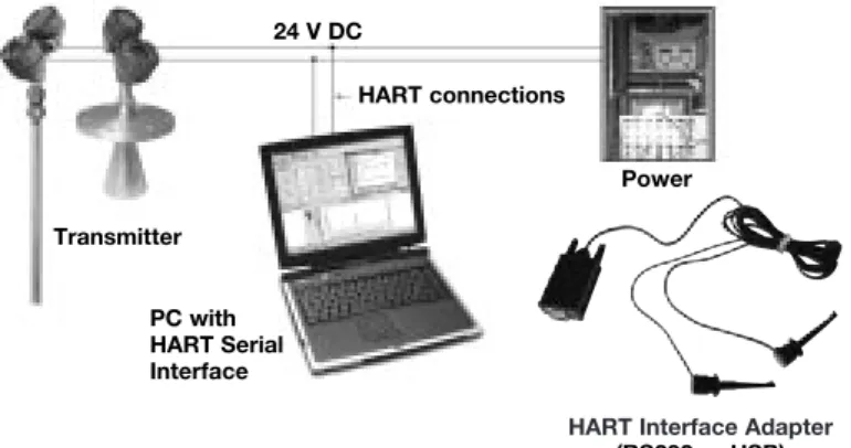
WHAT IS FDT, PACTware AND FDT
Power Transmitter
HART connections 24 V DC
PC with
• FDT (Field Device Tool) is a new interface code that describes the standardization between frame programs (e.g., PACTware) and DTMs (Device Type Manager). • PACTware (Process Automation Configuration Tool)
is a frame program. It is a device-independent software program that communicates with all approved DTMs. • DTM (Device Type Manager) is not a stand-alone
pro-gram but a device-specific software driver designed to operate within a frame program such as PACTware. It includes all special information needed to communicate with a specific device (e.g., Pulsar RX5). There are two basic categories of DTMs—Communication (HART, Fieldbus®, Profibus®, etc.) and Field Device (e.g. Pulsar
RX5 Radar transmitter).
MOST COMMONLY USED SCREENS
• Online parameterization: allows the user to configure the unit online.
• Offline parameterization: allows the user to configure the unit offline.
• Tank view: displays a common operating window graphi-cally showing % output of level.
• Echo curve: shows the actual waveform. The echocurve is an extremely useful tool for advanced configuration and troubleshooting.
• Process trend: all key data (Level, % Output, Loop) can be trended and saved, scales can be adapted.
• Device/diagnosis: the diagnosis: the diagnosis screen allows examination of all faults, warnings and interna-tional messages.
TROUBLESHOOTING
This program offers a wealth of information critical to effec-tive troubleshooting. If a problem should arise and factory assistance is necessary for analysis, be prepared to save and email the following files:
• ONLINE PARAMETERS:the complete list of confi gura-tion data.
• PROCESS TRENDinformation that includes the time of
upset/error condition.
• ECHO CURVE showing upset/error condition (when
possible).
• ERROR MONITOR(VIEW/ERROR MONITOR) including upset/error condition.
MINIMUM SYSTEM REQUIREMENTS
Following are general requirements for proper operation of
this program:
Pentium®II 500 MHz processor.
128 MB RAM.
120 MB free hard disk space.
Windows® XP/2000 (Service Pack 1) / NT 4.0 (Service
Pack 6).
Graphic Resolution 1024x768 (16-bit color). Internet Explorer 5.0.
RS232 serial interface.
RS232-HART or USB-HART serial interface for point-to-point connection or RS232-RS485 converter for connection to Hart Multiplexer.
HART communication DTM.
Transmitter with current HART revision.
CONNECTIONS
The following diagram shows a typical hardware confi gura-tion. Observe all safety codes when attaching to instrument loops in hazardous areas or when measuring flammable media. Computers are not intrinsically safe devices.
CONFIGURATION USING HART
®IMPORTANT: The digital HART® communication is superimposed on the
4-20 mA loop and requires a min. load resistance of 250 Ω and a max load resistance of 450 Ω. + + -Junction Control Room Display Power Supply Current Meter 250 Ω < RL< 450 Ω CONNECTIONS CHECK HART®
Connection of your Hart communicator:
• at power terminals (+) and (-) in wiring compartment • at first junction box between unit and control room.
Before starting the HART®configuration procedure – check if your HART®
commu-nicator is equipped with the proper Eclipse Device Descriptors (DD’s).
I/O start up the communicator Select NO: go offline
Select 4: utility Select 5: simulation Check manufacturer: Magnetrol
HART MENU
I/O Start up the device
1 Enter Device Set Up «DEVICE SET UP»
Press one of the following alphanumeric keys (if no key is sensed after 5 s, the unit will automatically jump to RUN mode and alternatively show Level/% Output and Loop signal
1 for entering Calibration «CALIBRATION» (see page 11 for additional informa-tion)
2 for entering Basic Set Up «BASIC SET UP» – general HART
3 for Advanced Set Up «ADVANCED SET UP» (see page 11 for additional infor-mation)
4 for entering Diagnostics «DIAGNOSTICS» (see page 11 for additional infor-mation)
5 for entering Review «REVIEW» to review all settings.
When the proper software version is not found, consult your local HART®Service
Center to load the correct Eclipse DD’s.
HCF Release Date HART Version Model Compatible with software
July 1998 Dev V1 DD V1 705 Version 1.2B & earlier
November 1998 Dev V1 DD V2 705 Version 1.2C ... 1.3D April 1999 Dev V3 DD V1 705 Version 1.4A ... 1.4C October 1999 Dev V4 DD V1 705a Version 1.5 and later June 2000 Dev V1 DD V2
Dev V1 DD V1
705 2.x 708
Version 2.0A ... 2.2C & earlier Version 1.0A ... 1.1B
October 2001 Dev V1 DD V2 Dev V2 DD V1
705 2.x 708
Version 2.3A ... 2.3E & earlier Version 1.2A ... 1.2C September 2003 Dev V3 DD V1 Dev V3 DD V1 Dev V3 DD V1 705 2.x 708 707
Version 2.4A ... 2.2B & earlier Version 1.3A ... 1.3C
Version 1.x and later April 2004 Dev V4 DD V1
Dev V4 DD V1
705 2.x 708
Version 2.5 and later Version 1.4A and later June 2005 Dev V1 DD V1 705 3.x Version 3.x & and later
HART ERROR MESSAGES
For easy PACTwareset up, consult
CONFIGURATION USING HART
®1 Calibration 2 Basic Setup 3 Advanced Setup 4 Diagnostics 5 Review 1 Device Setup 2 PV Lvl (or Vol) 3 PV % Out 4 PV Loop 5 Device Variables
1 Tag 2 Descriptor 3 Date 4 Message 5 Poll Address 6 Final Asmbly Num
1 Model 2 Manufacturer 3 Magnetrol S/N 4 Firmware Version 5 Tag 6 Descriptor 7 Date 8 Message 9 Poll Address 10 Final asmbly num 11 Device ID 12 Probe Model 13 Probe Mount 14 Measurement Type 16 Probe Length 15 Level Units 17 Level Offset 18 Volume Units 19 Dielectric Range 20 Sensitivity 21 PV is 22 SV is 23 TV is 24 QV is 25 4mA Set Point 26 20mA Set Point 27 Damping 28 System Fault State 29 Blocking Distance 30 SZ Fault State 31 SZ Height 32 Threshold 33 Intrface Threshold 34 IFC Thresh Ampl 35 Trim Level 36 4 mA Trim 37 20 mA Trim 38 Fiducial Type 39 Fiducial Gain 40 Level Gain 41 Neg Threshold Ampl 42 Pos Threshold Ampl 43 Compensation Mode 44 Upper Dielectric 45 7xK Correction 46 SZ Hysteresis 47 Universal rev 48 Field dev rev 49 Software rev 50 Num req preams 3 Measurement Type 4 Level Units 6 Level Offset 7 Volume Parameters 9 Sensitivity 8 Dielectric Range 10 PV is 11 Variable Selection 12 4 mA Set Point 13 20 mA Set Point 14 Damping 15 System Fault State 16 Blocking Distance 17 SZ Fault State 18 SZ Height 19 SZ Alarm Reset 20 Threshold 21 Interace Params 22 Trim Level 23 Date/Time/Initials 5 Probe Length 1 Probe Model 2 Probe Mount 1 Faults 2 Warnings 1 Loop Test 2 Present Status 4 Status History 5 Level Ticks 6 Fiducial Ticks 7 Fiducial Spread 8 Signal Strength 9 Elec Temperature 10 Interface Ticks 11 Interface Medium 12 Derating Factor 13 Target Ratio 14 Target Ticks 1 Sfwr Failure 2 CPU Failure 4 NV mem Failure 5 Default Params 6 No End of Ramp 7 No Probe 8 No Fiducial 9 No Signal 10 Loop Failure 11 Fiducial Shift 12 Slope Error 13 Channel Unbal 14 Hi Volume Alrm 15 Safe Zone Alrm 16 Fault 15 17 Fault 16 1 Trim Loop Current
2 Enter Password 3 Fiducial Type 4 Fiducial Gain 5 Level Gain 6 Neg Threshold Ampl 7 Pos Threshold Ampl 8 Compensation 9 Factory Settings 10 Sz Hystersis 11 Max Temperature 12 Min Temperature 13 Reset Temperatures 14 New User Passwords
1 Level 2 Volume 3 Interface Level 4 Interface Volume
3 Strapping Table Length 2 Strapping Table 1 Volume Units 3 QV IS 2 TV IS 1 SV IS
3 IFC Thresh Ampl 2 Interface Threshold 1 Upper Dielectric 1 Magnetrol S/N 2 Device ID 3 <Window> 4 Conversion Factor 5 Scale Offset 6 Factory Param 1 7 Factory Param 2 1 Compensation Mode 2 Upper Dielectric 3 Target Calibration 4 7xK Correction
1 Target Oper Mode 2 Target Calib Value 3 Auto Target Calib
1 Seal Leak 2 Fiducial Sprd 3 Hi Temperature 4 Lo Temperature 5 Calib Required 6 EOP Too High 7 EOP Too Low 8 Trim Required 9 Initializing 10 May Be Flooded 11 Dry Probe 12 Weak Signal 13 System Warning 14 Warning14 15 Warning15 16 Warning16
MENU: STEP BY STEP PROCEDURE – Foundation Fieldbus
®Eclipse 705
Screen
Action
Comment
Run mode
Configuration
1 2 3 4 5 6 8 9 10 11 12 13 14 15 16 17 *Level* *%Output* *Loop* Level xx.x cm %Output xx.x% Status OK PrbModel (select) Prb Mount (select) 7 Probe Ln xxx.x Offset xxx.x Dielctrc (select) 0% Set xxx.x 100% Set xxx.x FF Addr xxxx Fid Tick <Window> xxx Range xxx Gain xxx Cal MethodDiagnostics
18 Conv Fct xx.xxx 19 20 21 Scl Offs xx.x # Ticks xxxx Threshold (select)Transmitter Display Transmitter default display. Level «Level» and % Output
«%Output» values cycle every 5 seconds.
Transmitter Display Transmitter displays Level measurement in cm or in.
Transmitter Display Transmitter displays % Output measurement.
Transmitter Display Transmitter displays.
Selectthe type of probe used. Select as per the 3 first digits of the probe partnumber. The partnumber is shown on the nameplate: e.g. 705-510A-A11/7MR-A230-218, select 7xR-x from the list.
Selectthe type of probe
mounting.
Select NPT «NPT», Flange «Flange» or BSP «BSP».
Enterthe exact length of
probe.
Enter as per the 3 last digits of the probe partnumber on the nameplate: -rigid probes, enter value cm or inches,
- flexible probes, enter value in meters or feet
e.g. 705-510A-A11/7MR-A230-280, enter «218» cm probe length.
Enterthe offset value. See drawing on page ? Enterthe dielectric range
value of the media.
Select: «1.4–1.7»; «1.7–3» or «10–100»
None: level value for the 0 % point (EU_0%)
A small transition zone may exist at the top/bottom of the probe. See probe specifications pages 30, 31 and 32.
None: level value for the 100 % point (EU_100%)
A small transition zone may exist at the top/bottom of the probe. See probe specifications pages 30, 31 and 32.
None: Fieldbus Device Service Fieldbus Address, set in Control Room.
None, do not adjust. Diagnostic, factory setting.
None, do not adjust. Diagnostic, factory setting.
None, do not adjust. Diagnostic, factory setting.
None, do not adjust. Diagnostic, factory setting.
Enterthe calibration method
None, do not adjust. Diagnostic, factory setting.
None, do not adjust. Diagnostic, factory setting.
None, do not adjust. Diagnostic, factory setting.
EnterCFD «CFD».
EnterFixed «Fixed».
Unit default CFD «CFD». Only select Fixed «Fixed» in application
with low dielectric material over higher dielectric material and unit is reading incorrect level. Example: oil over water.
Select Dielectric Range«Dielctrc» of upper material.
MAINTENANCE
TROUBLESHOOTING SYSTEM PROBLEMS
Symptom
Problem
Solution
LEVEL, % OUTPUT and LOOP values
are all inaccurate.
Basic configuration data is questionable.
Reconfigure the Probe Length «Prb Ln»
and Offset «Offset». Check also the
Probe Model «Prb Model» / Probe
Mount «Prb Mount»
1) Ensure the Level is accurate. 2) Reconfigure Loop values. Interface level has significant emulsion. Examine process to reduce/eliminate
emulsion layer. LEVEL readings are repeatable but
consistently high or low from actual by a fixed amount.
Configuration data does not
accurately match probe length or tank height.
Ensure proper probe length «Prb Ln» & probe Model «Prb Model».
Adjust trim level value by the amount of noted inaccuracy.
LEVEL, % OUTPUT and LOOP values fluctuate.
Turbulence. Increase the Damping «Damping» factor
until the readings stabilize.
High frequency connection. Check Fiducial Spread «FidSprd»
(should be stable within ± 10 counts. LEVEL, % OUTPUT and LOOP
values all reading low vs. actual (level or volume applications).
Lower dielectric material over higher dielectric material, e.g. oil over water.
Select Fixed Threshold option «Fixed»
and/or select dielectric range from top layer. Coating, clumping or buildup on probe. Expected inaccuracies due to affect on
pulse propagation.
Dense, water based foam. Expected inaccuracies due to affect on pulse propagation.
LEVEL reading on Display is correct but LOOP is stuck on 4 mA
Basic configuration data is questionable.
Set Hart poll address «POLL ADR» to
«0». If not using HART®multi drop
HART device only: handheld will only read Universal Commands.
Most current Device Descriptors (DDs) are not installed in handheld.
Contact local HART service center for the latest DD’s. (see page 20) LEVEL reading on display is stuck
at full scale, LOOP is stuck at 20,5 mA.
Software believes probe is flooded (level near very top of probe).
Check actual level. If probe is not flood-ed, check for build up or obstructions near top of probe. Select higher dielec-tric range.
Check for condensation in probe con-nection. Add Blocking Distance. LEVEL, % OUTPUT and LOOP
values all at maximum level.
Possible configuration issue with single rod probe
1) Increase Blocking Distance 2) Increase Dielectric Range LEVEL, % OUTPUT and LOOP
values all reading high vs. actual.
Possible obstruction in tank affecting single rod probe.
1) Increase Dielectric Range until obstruction is ignored.
2) Relocate probe away from obstruc-tion.
LEVEL value reading high when should be zero.
Transmitter loose or disconnected from probe.
Ensure transmitter connected securely to probe.
MAINTENANCE
Display
Message Action Comment
OK None Normal operating mode
Initial None Program is Initializing, level reading held at 4 mA set point. This is a
transient condition.
DryProbe None Normal message for a dry probe. End of probe signal is being detected.
EOP Low End of Probe signal is out of range
1) Ensure probe length is entered correctly 2) Set transmitter to a lower dielectric range 3) Consult factory
EOP High End of Probe signal is out of range
1) Ensure probe length is entered correctly 2) Consult factory
WeakSgnl None. Signal amplitude is lower than desired.
1) Set transmitter to lower dielectric range 2) Increase sensitivity
Flooded? Loss of level signal possibly due to flooding, twin rod probes only
1) Decrease level in vessel
2) Set transmitter to lower dielectric range 3) Replace with Model 7MR Overfill probe
NoSignal No level signal being detected. 1) Ensure dielectric setting is correct for measured medium 2) Increase sensitivity
3) Confirm that the probe type is proper for the dielectric of the medium 4) Consult factory
No Fid Fiducial signal is not being detected
1) Check connection between probe and transmitter 2) Check for moisture on top of probe
3) Check for damaged gold pin on the high frequency connector 4) Consult factory
FidShift FidTicks shifted from expected value
1) Check connection between probe and transmitter 2) Check for moisture on top of probe
3) Check for damaged gold pin on the high frequency connector 4) Consult factory
Fid Sprd* Fiducial Ticks variation is excessive.
1) Check connection between probe and transmitter 2) Check for moisture on top of probe
3) Consult factory
No Probe Electronics does not sense that a probe is attached
1) Ensure proper connection between probe and transmitter 2) Check for damaged gold pin on the high frequency connector
SZ Alarm Safety Zone alarm has been tripped, loop current fixed at SZ Fault
Decrease level in vessel
Hi Temp Present temperature in electronics compartment is above +80° C
1) Transmitter may need to be moved to ensure ambient temperature is within specification
2) Change to remote mount transmitter
MAINTENANCE
Display
Message Action Comment
Lo Temp Present temperature in electronics compartment is below -40° C.
1) Transmitter may need to be moved to ensure ambient temperature is within specification
2) Change to remote mount transmitter
HiVolAlm Level more than 5% above highest point in strapping table.
Verify strapping table is entered correctly.None. Signal amplitude is lower than desired.
Sys Warn Unexpected but non-fatal software event
Consult factory
TrimReqd Factory set Loop values are defaults, loop output may be inaccurate
Consult factory
Cal Reqd Factory set default calibration parameters are in use, level reading may be inaccurate
Consult factory
SlopeErr Ramp circuit generating improper voltage
Consult factory
LoopFail Loop current differs from expected value
Consult factory
Note: In case of loop failure, error signal will follow the failing trend;
meaning the unit will show 3.6 mA when the reviewed loop current by the device is found too low. The unit will show 22 mA in case the reviewed loop current is found too high.
No Ramp No End-of-Ramp signal detected Consult factory
DfltParm Internal non-volatile parameters have been defaulted
Consult factory
EE Fail EEPROM error allowing watch-dog timer to expire
Consult factory
CPU Fail A-D converter time out allowing watchdog timer to expire
Consult factory
SfwrFail A fatal software error allowing watchdog timer to expire
Consult factory
PACTware™PC Program
The Eclipse Model 705 offers the ability to do Trending and Echo Curve analysis using a PACTware DTM. This is a powerful
troubleshoot-ing tool that can aid in the resolution of some of the Error Messages shown above. Refer to Bulletins 59-101 and 59-601 for more information.
MAINTENANCE
TROUBLESHOOTING APPLICATIONS: Level
TROUBLESHOOTING APPLICATIONS: Interface Most frequent application problems that may occur, media buildup on the probe and stratification, are covered here. Media buildup on the probe is not a problem in most cases–Eclipse circuitry typically works very effectively. Media buildup should be viewed as two types – Film Coating and Bridging.
A twin rod probe should alwaysbe chosen if media buildup
is minor. For more extreme buildup, single rod GWR probes should be used.
• Continuous Film Coating
The most typical of coating problems where the media
forms a continuous coating on the probe. Eclipse will continue to measure effectively with some small degra-dation in performance. A problem can develop if the product begins to buildup on the spacers that separate the probe elements. High dielectric media (e.g, water-based) will cause the greatest error.
• Bridging
Media that is viscous or solid enough to form a clog, or
bridge, between the elements causes the greatest degradation in performance. High dielectric media (eg. water-based) will show as level at the location of the bridging.
• Stratification/Interface
The Eclipse transmitter is designed to measure the first air/media interface it detects. It will not measure further liquid/liquid interfaces. However, a low dielectric over a high dielectric application can cause a measurement problem if the net level of the low dielectric medium becomes small enough (a few inches) to cause the elec-tronics to trigger on the high dielectric medium that lies beneath it. Select the Fixed Threshold option to read the upper medium. Film Coating Bridging Film Coating Outer tube Inner rod Bridging Oil
ε
r2.0 Emulsion Layer Waterε
It is not uncommon for interface applications to have an
emulsion layer form between the two media. This emulsion layer may pose problems for Guided Wave Radar as it may decrease the strength of the reflected signal. Since the properties of this emulsion layer are difficult to quantify, applications with emulsion layer should be avoided with Eclipse.
MAINTENANCE
TROUBLESHOOTING APPLICATIONS: Single Rod type GWR probe Most frequent application problems that may occur, media
buildup on the probe and stratification, are covered here. Significant buildup on the probe is not a problem in most cases–Eclipse circuitry typically works very effectively.
• Nozzles (only for 7MF/7M1/7M2/7MJ)
Nozzles can create false echoes that can cause diag-nostic messages and/or errors in measurement. If bad calibration parameters «BAD CAL PARAMTRS» is dis -played when first configuring the instrument:
1. Ensure the probe length «Prb Ln» as entered in the
software is equal to the actual probe length (see page 10). This value must be changed if the probe is cut shorter from the original length.
2. Increase the blocking distance «BlockDis» value
until the message is eliminated; 20 mA point may need to be lowered.
3. Increase the dielectric range a small amount to aid in reducing echoes in nozzle. Increasing the dielectric settings may cause instrument to lose level of lower dielectric media; consult factory.
• Obstructions (only for 7MF/7M1/7M2/7MJ)
If the level reading repeatedly locks on to a specific level higher than the current level, it may be caused by a metallic obstruction. Obstructions in the vessel (e.g. pipes, ladders) that are located close to the probe may cause the instrument to show them as level.
1. Refer to the Probe Clearance Table
2. Increase the dielectric range a small amount to aid in reducing echoes in nozzle. Increasing the dielectric settings may cause instrument to lose level of lower dielectric media; consult factory.
• Coating/build-up (only for 7MF/7M1/7M2/7MJ)
The Eclipse®705 wih Single Rod Probe was designed to
operate effectively in the presence of media building up. Some expected error may be generated based upon the following factors:
① Dielectric of the media that created the coating
② Thickness of the coating
③ Length of the coating above the present level • Coating/build-up (only for 7M7/7M5)
Continuous film coating is where the media forms a thin continuous coating on the probe. Eclipse®will continue
to measure effectively with some degradation in perfor-mance. The degradation is proportional to the dielectric of the media and the thickness of the coating up to a degree that the unit will see coating as a level. Higher dielectric media (eg. water based) will show sooner as a level at the location of the build up.
①
②
③
Obstruction Nozzles •2" diameter minimum • Ratio of diameter: length should be > 1:1• Do not use pipe reducers (restriction)
Coating Build-up
Distance to probe Acceptable objects
< 150 mm (6") Continuous, smooth, parallel, conductive surface (e.g. metal tank wall); probe should not touch tank wall
> 150 mm (6") < 1"/DN25 diameter pipe and beams, ladder rungs
> 300 mm (12") < 3"/DN80 diameter pipe and beams, concrete walls > 450 mm (18") All remaining objects