Universal Serial Bus
Communications Class
Subclass Specification for
Ethernet Emulation Model Devices
Revision 1.0
February 2, 2005
ii February 2, 2005
Revision History
Rev Date Filename Comments
0.6 8/25/03 CDC_IPUSB06.DOC First Draft for internal CDC review
0.7 10/1/03 CDC_IPUSB07.DOC Comments / Suggestions from 10-1-03 CDC DWG. 0.7a 12/1/03 CDC_IPUSB07.DOC Comments / Suggestions from CDC reflector 0.7b 12/5/03 CDC_IPUSB07b.DOC Comments / Suggestions from CDC members prior to
meeting
.0.7c 12/6/03 CDC_IPUSB07c.DOC Comments / Suggestions from 12-5-03 CDC DWG. .08rc0 2/17/04 CDC_EEM08rc0.doc Comments / Suggestions from 2-5-04 DWG an RR’s. .08rc1 2/26/04 CDC_EEM08rc1.doc Move IP over EEM information to separate document. .08rc2 4/7/04 CDC_EEM08rc2.doc Comments and suggestions from 4-7-2004 group
meeting.
.08rc3 4/7/04 CDC_EEM08rc3.doc Comments and suggestions from 4-7-2004 dinner meeting.
.08rc4 4/9/04 CDC_EEM08rc4.doc Comments and suggestions from 4-7-04 DWG. .08rc5 5/26/04 CDC_EEM08rc5.doc Comments and suggestions from 5-26-04 working
session.
.08rc6 5/26/04 CDC_EEM08rc6.doc Updates from meeting feedback. .08rc7 6/29/04 CDC_EEM08rc7.doc Final updates for .8 approval
.08 8/5/04 CDC_EEM08.doc .8 submit
.08a 10/6/04 CDC_EEM08a.doc Define EEM Command packet. Add echo and suspend. .09rc1 12/1/04 CDC_EEM09rc1.doc Accept changes to remove change bars and prepare for
public release.
.09 12/8/04 CDC_EEM09.doc Change title to reflect numerical promotion. 1.0 2/2/05 CDC_EEM10.doc Title change and removal of obsolete references.
Copyright © 2004, 2005 USB Implementers Forum, Inc. (USB-IF). All rights reserved.
INTELLECTUAL PROPERTY DISCLAIMER
THIS SPECIFICATION IS PROVIDED “AS IS” WITH NO WARRANTIES WHATSOEVER INCLUDING ANY WARRANTY OF MERCHANTABILITY, FITNESS FOR ANY PARTICULAR PURPOSE, OR ANY WARRANTY OTHERWISE ARISING OUT OF ANY PROPOSAL, SPECIFICATION, OR SAMPLE. A LICENSE IS HEREBY GRANTED TO REPRODUCE AND DISTRIBUTE THIS SPECIFICATION FOR INTERNAL USE ONLY. NO OTHER LICENSE, EXPRESS OR IMPLIED, BY ESTOPPEL OR
OTHERWISE, TO ANY OTHER INTELLECTUAL PROPERTY RIGHTS IS GRANTED OR INTENDED HEREBY.
AUTHORS OF THIS SPECIFICATION DISCLAIM ALL LIABILITY, INCLUDING LIABILITY FOR INFRINGEMENT OF PROPRIETARY RIGHTS, RELATING TO IMPLEMENTATION OF
INFORMATION IN THIS SPECIFICATION. AUTHORS OF THIS SPECIFICATION ALSO DO NOT WARRANT OR REPRESENT THAT SUCH IMPLEMENTATION(S) WILL NOT INFRINGE SUCH RIGHTS.
iv February 2, 2005
Contributors
Russ Winsper Apple Computer Michael Montgomery Axalto
Bill Russell Canon
Robbie Harris Hewlett Packard Smith Kennedy Hewlett Packard John Van Boxtel Hewlett Packard Joel Silverman Kawasaki LSI Ariel Sobelman M-Systems Joe Decuir MCCI Terry Moore MCCI
Paul Berg MCCI
Randy Aull Microsoft Corporation Fred Bhesania Microsoft Corporation Igor Kostic Microsoft Corporation Brian King Microsoft Corporation Aditya Dube Microsoft Corporation Jim Blackson YE Data
Table of Contents
1 Introduction... 7
1.1 Purpose ... 7
1.2 Scope... 7
1.3 Related Documents ... 9
1.4 Terms and Abbreviation ... 9
2 Management Overview... 12
2.1 What is Ethernet Emulation Model (EEM)?... 12
3 Assumptions and Constraints ... 13
3.1 USB Specification... 13
3.2 Class-Specific Codes for EEM Devices... 13
3.2.1 Communication Class Code ... 13
3.2.2 Communication Class Subclass Codes... 13
3.2.3 Communication Class Protocol Codes... 13
3.3 Device Framework... 14 3.3.1.1 Function Addressing ... 14 4 Functional Overview ... 15 4.1 Function Models ... 15 4.2 Endpoint Requirements ... 15 5 Functional Characteristics ... 16 5.1 EEM Packet ... 16
5.1.1 EEM Packet Format... 16
5.1.2 EEM Packet Types ... 17
5.1.2.1 EEM Data Packet... 17
5.1.2.2 EEM Command Packet... 18
5.1.2.2.1 Echo ... 19 5.1.2.2.2 Echo Response... 19 5.1.2.2.3 SuspendHint... 20 5.1.2.2.4 ResponseHint... 20 5.1.2.2.5 ResponseCompleteHint ... 20 5.1.2.2.6 Tickle Command ... 21 5.1.2.3 Special Packets... 21
5.1.2.3.1 Zero Length EEM (ZLE) ... 21
5.1.3 EEM Packet Handling... 22
5.1.3.1 Receiving Packets... 22
5.1.3.1.1 Receive Command Packet... 23
5.1.3.1.2 Receive Data Packet... 23
5.1.3.2 Sending Packets ... 24
5.2 Transfers... 25
5.3 Wakeup Support ... 26
6 Device Requests... 27
vi February 2, 2005
Appendix B: Example Driver Architecture ... 30
Appendix C: Network MAC Configuration Example... 32
Appendix D: EEM Frequently Asked Questions ... 33
What are the benefits of EEM? ... 33
Why not use Ethernet?... 33
Does this replace the need for USB device classes? ... 33
How to I get a MAC address for my company? ... 33
Appendix E: EEM Packet handling examples ... 34
E.1 Sending small EEM Packets ... 34
E.2 Sending large EEM packets (> bMaxpacket) ... 36
E.3 Bundling EEM Packets ... 38
Appendix F: EEM Hardware Architecture Walkthrough... 40
1 Introduction
1.1 Purpose
This document specifies the behavior of Ethernet Emulation Model (EEM) Devices. The document was designed with multifunction devices in mind, but is limited in no way to this implementation alone.
1.2 Scope
This document specifies new device subclasses intended for use with Communication devices, based on the Universal Serial Bus Class Definitions for Communication Devices specification [USBCDC].
The intention of this specification is that all material presented here be upwards-compatible extensions of the [USBCDC] specification. New numeric codes are defined for subclass codes, protocol codes, management elements, and notification elements.
In some cases material from [USBCDC] is repeated for clarity. In such cases, [USBCDC] shall be treated as the controlling document.
In this specification, the word ‘shall’ or ‘must’ is used for mandatory requirements, the word ‘should’ is used to express recommendations and the word ‘may’ is used for options.
1.3 Related
Documents
USB2.0
Universal Serial Bus Specification
, revision 2.0 (also referred to as
the
USB Specification
). This specification is available on the
World Wide Web site
http://www.usb.org
.
USBCCS1.0
Universal Serial Bus Common Class Specification, revision 1.0.
This specification is available on the World Wide Web site
http://www.usb.org
USBCDC1.1
Universal Serial Bus Class Definitions for Communication
Devices
, Version 1.1. This specification is available on the World
Wide Web site
http://www.usb.org
.
USBMASS1.1
Universal Serial Bus Mass Storage Class Specification Overview,
Release 1.1. This specification is available on the World Wide
Web site
http://www.usb.org
.
USBPRINT1.1
Universal Serial Bus Device ClassDefinition for Printing Devices,
Release 1.1. This specification is available on the World Wide
Web site
http://www.usb.org
.
USB_STIL_IMG1.0
Universal Serial Bus Still Image Capture Device Definition,
Revision 1.0. This specification is available on the World Wide
Web site
http://www.usb.org
.
IEEE 802.3-2002
(ISO/IEC 8802-3)
Carrier sense access with multiple collision detection
1.4 Terms and Abbreviation
Term Description
Anycast Communication between a single sender and the nearest of several receivers in a group.
ARP Address Resolution Protocol associates an IP address to a hardware address called a Media Access Control (MAC) address.
probe. sender's IP address set to 0s.
Descriptor Data structure used to describe a USB device capability or characteristic
Device A logical or physical entity that performs a function. The actual entity described depends on the context of the reference. At the lowest level, device may refer to a single hardware component, as in a memory device. At a higher level, it may refer to a collection of hardware components that perform a particular function, such as a USB interface device. At an even higher level, device may refer to the function performed by an entity attached to the USB; for example, a data/FAX modem device. Devices may be physical, electrical, addressable, and logical. When used as a non-specific
reference, a USB device is either a hub or a function.
DHCP Dynamic Host Configuration Protocol is a protocol for organizing and simplifying the administration of IP configuration for computers in a network.
ECM Ethernet Control Model. as defined in CDC Device Class specification.
EEM Ethernet Emulation Model
EEM Transfer USB Transfer containing one or more EEM packets
ENA External Network Adapter
Ethernet IEEE 802.3
Firewall A filtering module located on a gateway machine that examines all incoming and outgoing traffic to determine if it may be routed to its destination.
Function Device capabilities exposed over the USB cable. IP address An IP address is a unique number, which identifies a
computer in an IP network.
MAC address Media Access Control address is more specific than an IP address and cannot be changed because it is specific to each network hardware device.
Multicast Communication between a single sender and multiple receivers on a network.
Multifunction device A device of peripheral that exposes one or more functions or services to an end user. Exposed services can but do have to
be exposed as USB functions.
Port A port is a 16-bit number (the allowed range being 1 through 65535) used by the TCP and UDP protocols at the transport layer. Ports are used to address applications (services) that run on a computer.
Service Device capabilities exposed over an EEM function.
Socket A socket represents a single connection between two network applications.
Unicast Communication between a single sender and a single receiver over a network
ZLE Zero Length EEM Packet. Refer to 5.1.2.3.1.
2 Management
Overview
Ethernet Emulation Model (EEM) is a specification for inexpensive and efficient transport of Ethernet frame across the USB bus. EEM prepends the Ethernet frame (Ethernet header, payload, and CRC) with a small header to enable concatenation of frames within a USB transfer. EEM enables the leveraging of the extensive infrastructure that is implemented above Ethernet in USB hosts. How the corresponding network infrastructure layered above Ethernet is implemented within the device is beyond the scope of this specification. Examples of this include but are not limited to transports IPv4 and IPv6, discovery protocols such as UPnP and Rendezvous, and web applications.
EEM’s endpoint requirements consist solely of a bulk pair (In and Out).
Unlike CDC ECM, EEM does not extend an interface across the USB bus but instead considers the USB bus to be a vehicle for moving Ethernet packets.
EEM enables leveraging the network stack over USB and Ethernet interfaces.
Prior to EEM, specialized services needed to either create a device class within the USB DWG or a Vendor specific Device. Utilizing EEM allows existing upper layer networking protocols to discover and use new services.
2.1 What is Ethernet Emulation Model (EEM)?
EEM is the encapsulation of Ethernet frames for transport across the USB bus.
Simulated Ethernet Bus
HOST
USB MAC2Device
NIC Driver NIC Driver MAC13 Assumptions and Constraints
This section describes assumptions and constraints related to compliance.
3.1 USB
Specification
3.2 Class-Specific Codes for EEM Devices
This section lists the codes for the Communication Device Class, Communication Interface Class and Data Interface Class, including subclasses and protocols. These values are used in the DeviceClass, bInterfaceClass, bInterfaceSubClass, and bInterfaceProtocol fields of the standard device descriptors as defined in chapter 9 of the USBSpecification.
3.2.1 Communication Class Code
The following table defines the Communications Device Class code: Table 1 Communication Device Class Code
Code Class
02h Communication Device Class
3.2.2 Communication Class Subclass Codes
The following table table defines the Communication Subclass code: Table 2 Class Subclass Code
Code Subclass
0Ch Communication Device Subclass / EEM
3.2.3
Communication Class Protocol Codes
Table 3 Class Protocol Code
Code Protocol
07h EEM
If a Communication Class interface appears with multiple alternate settings, all alternate settings for that interface shall have the same bInterfaceClass, bInterfaceSubclass and bInterfaceProtocol codes.
3.3 Device
Framework
3.3.1.1 Function Addressing
Each EEM function must have a unique MAC address. The registration process and fees for obtaining MAC addresses is covered on the IEEE website (http://standards.ieee.org/faqs/OUI.html.).
4 Functional
Overview
4.1 Function Models
[USB2.0] defines “function” as a “USB device that provides a capability to the host, such as an ISDN connection, a digital microphone, or speakers”. Further, in section 5.2.3, it says “Multiple functions may be packaged into what appears to be a single physical device…. A device that has multiple interfaces controlled independently of each other is referred to as a composite device.” We therefore adopt the term “function” to describe a set of one or more interfaces which taken together provide a capability to the host.
This document defines the following new kinds of functions: • Ethernet Emulation Model (EEM)
4.2 Endpoint Requirements
The EEM Device Class uses the standard Endpoint descriptor, as defined in chapter 9 of the USB Specification.
The only endpoint requirement imposed by this specification is a single pair of bulk-in/bulk-out endpoints.
A pair of bulk endpoints, an IN and an OUT, would be used to send and receive the frames (as shown in Figure 2 Endpoint Requirements).
Control Endpoint 0 In/Out
EEM Inteface
EEM Endpoint x In EEM Endpoint x Out
5 Functional
Characteristics
5.1 EEM
Packet
The payload of the USB packet contains any combination of a single EEM Packet (refer to Figure 3 USB Packet with single EEM payload), two or more EEM Packets (refer to Figure 4 USB Packet with EEM bundle) or a split EEM packet (refer to Figure 5 USB Packet with EEM bundle and split EEM).
Figure 3 USB Packet with single EEM payload
Figure 4 USB Packet with EEM bundle
Figure 5 USB Packet with EEM bundle and split EEM
Figure 6 USB Packet with split EEM
EEM packets can be split across USB packets but shall not be split across USB transfers.
5.1.1 EEM Packet Format
The packet format defines an EEM packet. For information regarding USB packets refer to [USB2.0] specification. Details packets formats can be found in section 8.4 of the [USB2.0] specification.
Transfer Type Packet Format
Bulk Transfer Refer to section 5.8 of [USB2.0] specification
Table 4 USB Packet Format Reference
An EEM data packet, contains a header prepended to an Ethernet Frame.
Figure 7 EEM Packet
5.1.2 EEM Packet Types
The EEM Packet header contains a bmType field to denote whether EEM packet is an EEM Data packet or EEM Command Packet.
Figure 8 EEM Packet Header Example
Table 5 Values for bmType
bmType Purpose
0 Default. EEM data payload
1 EEM Command
5.1.2.1 EEM Data Packet
An EEM Data packet is used to transport Ethernet frames over a USB cable. The EEM Data Packet header contains a bmCRC field to denote whether the CRC field in the Ethernet Frame contains a calculated CRC or a sentinel value of 0xdeadbeef followed by the length of the Ethernet Frame.
Figure 9 EEM Data Packet Header Pictorial Table 6 EEM Data Packet Format
Offset Field Size Value Description
0 bmEEMDataHdr 2 Bit mask D15: bmType. Set to 0 D14: bmCRC
D13-D0:Length of Ethernet Frame
Table 7 Values for bmCRC bmCRC value Purpose
0 Ethernet Frame CRC is set to 0xdeadbeef 1 Ethernet Frame CRC has been calculated
5.1.2.2 EEM Command Packet
An EEM Command packet provides local USB link management. The EEM command header and EEM command payload shall not be transmitted beyond USB driver layers.
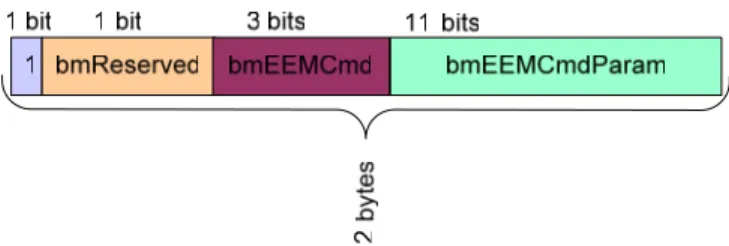
Figure 10 EEM Command Packet Header Pictorial Table 8 Values for bmReserved
bmReserved Purpose 0 Default
Table 9 Values for bmEEMCmd bmEEMCmd Purpose 0 Echo 1 Echo response 2 SuspendHint 3 ResponseHint 4 ResponseCompleteHint 5 Tickle
6-7 Reserved for future use.
5.1.2.2.1 Echo
An Echo command is used for USB link validation. EEM Echo commands can be initiated by either host or device..
Upon receipt of an Echo command, an Echo Response command packet with identical command payload is sent.
Table 10 EEM Packet format for Echo Command
Offset Field Size Value Description
0 bmEEMCommandHdr 2 Bit mask D15: 1 D14: 0 D13-D11: 000b
D10-D0: EEM Echo Length
1 EchoData Length Variable Command Payload (Data to be echoed)
5.1.2.2.2 Echo Response
Table 11 EEM Packet format for Echo Response Command
Offset Field Size Value Description
0 bmEEMCommandHdr 2 Bit mask D15: 1 D14: 0 D13-D11: 001b
D10-D0: EEM Echo Length
1 EchoReturn Length Variable Command Payload (Data to be echoed)
5.1.2.2.3 SuspendHint
A SuspendHint is initiated by the peripheral to inform the host the peripheral has entered a state where it is safe to suspend. The host is not required to make use of this information.
Table 12 EEM Packet format for SuspendHint Command
Offset Field Size Value Description
0 bmEEMCommandHdr 2 Bit mask D15: 1 D14: 0 D13-D11: 010b
D10-D0: 0000 0000 000b
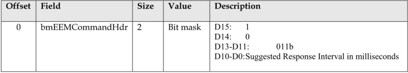
5.1.2.2.4 ResponseHint
A ResponseHint is initiated from the peripheral to inform the host of a suggested response time interval in which the host may suspend polling of the device. After receiving this command, the host may suspend polling for a time interval not to exceed the specified response time interval. The host may choose to ignore this hint.
Table 13 EEM Packet format for ResponseHint Command
Offset Field Size Value Description
0 bmEEMCommandHdr 2 Bit mask D15: 1 D14: 0
D13-D11: 011b
D10-D0: Suggested Response Interval in milliseconds
5.1.2.2.5 ResponseCompleteHint
A ResponseCompleteHint command is initiated from the peripheral to inform the host the peripheral has no further information to transmit to the host at this time. The device shall not have any further information to transmit to the
host until one or more of the following conditions have been met: • · Host transmits data to the device.
• · Timeout of bmEEMCmdParam seconds has expired.
After receiving this command, the host may suspend polling until either the host transmits data to the device, or until a time interval not to exceed the specified timeout has elapsed. The host may choose to ignore this hint.
If the timeout expires before the host sends data, the host may send a Tickle command to the device. However, since the host may choose to ignore this hint, the device cannot depend upon a Tickle command being sent upon timeout.
Table 14 EEM Packet format for ResponseCompleteHint Command
Offset Field Size Value Description
0 bmEEMCommandHdr 2 Bit mask D15: 1 D14: 0)
D13-D11: 100b D10-D0: Timeout in seconds
5.1.2.2.6 Tickle Command
A Tickle command may be initiated by the host to signal a timeout from a ResponseCompleteHint command. Because the host may choose to ignore the ResponseCompleteHint command, the device cannot depend upon a Tickle command being sent upon timeout.
Table 15 EEM Packet format for Tickle Command
Offset Field Size Value Description
0 bmEEMCommandHdr 2 Bit mask D15: 1 D14: 0
D13-D11: 101b D10-D0: 0000 0000 000b
5.1.2.3 Special Packets
5.1.3 EEM Packet Handling
EEM packet formats and handling of those packets is identical for host to device or device to host transactions.
5.1.3.1 Receiving Packets
Figure 12 Example EEM Packet Receive Flowchart is an example algorithm for receiving USB transfers containing EEM packets.
Figure 12 Example EEM Packet Receive Flowchart 5.1.3.1.1 Receive Command Packet
TRUE FALSE eemCmdHdr.bmReserved == 1? Discard EEM Packet Process EEMCmd
Figure 14 Example EEM Data Packet Receive Flowchart 5.1.3.2 Sending Packets
The transfer format defines an EEM transfer. For information regarding USB transfers refer to [USB2.0] specification. Details regarding USB transfers can be found in section 5.4 of the [USB2.0] specification. As per [USB2.0] specification, section 5.8.3, the last packet of the USB transfer shall be a short packet, to mark the end of the transfer. If the buffered data would not result in the last packet being a short packet, i.e. the data length is an exact multiple of bMaxpacket, an additional packet shall be added to insure that the last packet is a short packet. This additional packet can either be a ZLP (zero length packet) or ZLE (refer to 5.1.2.3.1) packet.
5.3 Wakeup
Support
If the device indicates that it supports wakeup, and the host has set the remote wakeup feature in this session, and all other (USB 2.0 specification standard) conditions for generating remote wakeup signaling have been met, and the EEM function has data to send to the host now, THEN the device shall generate a remote wake signal.
6 Device
Requests
No additional class-level requests are defined by this specification. Existing CDC or WMC class requests are not supported unless otherwise called out.
Appendix A: EEM Installation Example
A.1 Installation Overview
Refer to Figure 16 Installation Example (Big Picture) as a guide for the installation algorithm listed below.
Step 0: Device is turned on and/ or plugged in.
Step 1: USB installation occurs. Refer to Appendix A.2 for more details. Step 2: Pending read from EEM device class to initiate network addressing.
Step 3: Network addressing occurs. Network addressing (or equivalent) would be covered in the appropriate Ethernet compatible Network layer documentation.
Step 4: Service Installation begins. Service discovery details will be found in Ethernet compatible service discovery documentation.
Step 5: EEM function and child services are ready for use.
A.2 USB Installation Overview
Appendix B: Example Driver Architecture
Implementers are free to use whatever driver structure best suit their technical and commercial goals. However, for readers unfamiliar with the details of using multifunction (multiple services) devices, this section shows an example driver architecture that can be used to integrate the functionality of an example EEM peripheral into an operating system. This section is informative, not normative.
For the purposes of discussion, we assume a relatively complicated device, containing the following services: • Web server • Storage • Print • Fax • Scan
Appendix C: Network MAC Configuration Example
Figure 19 One or more EEM's per Host NICs
Figure 19 One or more EEM's per Host NICs shows a configuration where one or more devices are connected to a single NIC driver in the host PC. In this example, MAC1 is derived from the host software implementation. MAC’s two and three come from their perspective peripherals.
Figure 20 MAC Example
Figure 20 MAC Example shows a configuration where each device connects to a single NIC driver in the host PC. In this example, MAC’s one and two come from their perspective peripherals.
Appendix D: EEM Frequently Asked Questions
What are the benefits of EEM?
EEM enables a network interface over USB. Software can be leveraged between network and USB connected peripherals.
Why not use Ethernet?
There are many reasons to use USB plug instead of an Ethernet plug. This is a vendor specific model. Common reasons are listed below. The list is not conclusive, but can serve as a reference to some of the many possible reasons.
1. Connector size
USB based peripherals can choose from a number of standard form factors. 2. Electrical
The USB cable provides power. Ethernet does not. 3. Install base
The peripheral may wish to have enable EEM to a market segment that has a USB connector.
Does this replace the need for USB device classes?
No. The goal of EEM is to provide an economical network interface over USB. Using services over a network connection is a natural extension of this technology. The benefits of enumerating services over TCP/IP over EEM or a USB device class need to be weighed by the hardware vendor.
How to I get a MAC address for my company?
The registration process and fees are covered on the IEEE website (http://standards.ieee.org/faqs/OUI.html.).
Appendix E: EEM Packet handling examples
E.1 Sending small EEM Packets
Figure 21 Sending EEM packets < bMaxPacket
• Step 1: Host based Ethernet driver sends Ethernet frame to USB driver.
• Step 2: Host based USB driver accepts Ethernet frame from upper driver. Host based USB driver creates EEM packets by prepending header to Ethernet Frame.
• Step 3: Host based USB drivers packs EEM Packet into USB Packet. Note: This example assumes sizeof(enet_frame) < bMaxPacket.
• Step 4: Host based USB driver sends USB Packet (with payload) across the wire to the device.
• Step 5: Device based USB driver accepts the USB Packet.
• Step 6: Device based USB driver unpacks the EEM packet to get header and Ethernet Frame. Ethernet Frame is sent to device based Ethernet driver.
E.2 Sending large EEM packets (> bMaxpacket)
Figure 22 Sending enet frames > bMaxPacket
• Step 2: Host based USB driver accepts Ethernet frame from upper driver. . Host based USB driver creates EEM packets by prepending header to Ethernet Frane.
• Step 3: Host based USB drivers splits EEM packet to bMaxpacket sized chunks.
• Step 4: Each chunk is packed into a USB Packet.
• Step 5: Host based USB driver sends USB Packet(s) (with payload) across the wire to the device. Device based USB driver accepts the USB Packet.
• Step 6: Device based USB driver unpacks the chunks.
• Step 7: EEM packet is reassembled. .Ethernet Frame is extracted from EEM packet. Ethernet frame is sent to device based Ethernet driver.
E.3 Bundling EEM Packets
Figure 23 Bundling Ethernet Frames
• Step 2: Host based USB driver accepts Ethernet frame(s) from upper driver. Host based USB driver creates EEM packets by prepending header to Ethernet Frame.
• Step 3: EEM packets are bundles into USB Packet up to bMaxpacket.
• Step 4: Host based USB driver sends USB Packet(s) (with payload) across the wire to the device. Device based USB driver accepts the USB Packet(s).
• Step 5: Device based USB driver unpacks USB Packet. Ethernet Frame is extracted from EEM packet. Ethernet frame is sent to device based Ethernet driver.
• Step 6: Ethernet Frame is reassembled from chunks and sends frame to device based Ethernet driver. Chunks that do no make up an existing frame are held until the rest of the frame arrives or an error condition.
Appendix F: EEM Hardware Architecture Walkthrough
EEM simulates an Ethernet bus and removes the Ethernet hardware (refer to Figure 24 EEM ).
Figure 24 EEM Walkthrough 1
The simulated Ethernet bus is moved to the host to reduce firmware footprint (refer to Figure 25 EEM Walkthrough 2).
Figure 25 EEM Walkthrough 2
EEM (refer to Figure 26 EEM Walkthrough 3) pushes the simulated Ethernet bus to host based software.
Figure 26 EEM Walkthrough 3
Over the USB cable, encapsulated Ethernet frames flow starting with the destination MAC address and ending just before the frame checksum. (The frame checksum is not needed since USB is a reliable transport.) USB transfers could be used to encapsulate the frames or a header could precede the frame for fragmentation, etc.
EEM is implemented by writing a pseudo network adapter driver for both the host side and device side networking stack (which are probably different). The term pseudo is used because the network adapter driver does not control a traditional Ethernet chip but instead communicates with the USB host or device controller. This pseudo network adapter acts like a traditional Ethernet network adapter both sending and receiving packets but most importantly responding to key control and status operations.
A key control operation is the setting of the hardware unicast and multicast filters. Received frames which don’t pass the filters … broadcasts always pass … are discarded. In the absence of software bridging, there should be no extraneous frames received and no frames should be discarded.
Key status operations are returning the permanent hardware address, connection status and statistics. The permanent hardware address is used by the network stack to fill in the source hardware address for frames to be sent. Connection status is used both for display and control of higher level protocols like DHCP. Statistics are for display and analysis.
Appendix G: Ethernet Bridging
An EEM device may be a bridge and may be bridged but neither are required.
Communication between EEM devices (on the same USB bus) requires additional USB host implementation.