361
UTILIZAREA UNEI METODE INOVATIVE PENTRU ANALIZA
STRUCTURALĂ A APARATULUI DE DISTRIBUTIE UTILIZAT LA
MAŞINILE PNEUMATICE DE SEMĂNAT PLANTE PRĂŞITOARE
/
USE OF AN INNOVATIVE METHOD FOR STRUCTURAL
ANALYSIS OF THE DISTRIBUTION DEVICE USED IN
PNEUMATIC MACHINES FOR WEEDING PLANT SOWING
CRISTEA O-D., MATACHE M-G., MATEESCU M., MARIN E.
INMA Bucharest / Romania E-mail: [email protected]
Keywords: structural analysis, distribution device, weeding plant sowing
ABSTRACT
The topic addressed is a computer-aided design (CAD) method combined with computer-aided engineering (CAE) used in the analysis of choosing the optimal constructive variant of the distribution device used in pneumatic machines for weeding plant sowing. The CAD configurations, realized by the 3D
parametric modeling using the
SolidWorks program, were subjected to
structural analysis (von Mises equivalent stress distribution, relative displacement field distribution and safety factor). Based on the resulting data, the mass/resistance
coefficient for the 3 analyzed
configurations were determined. The comparison of these indicators led to the choice of the optimal constructive variant,
namely the most efficient one.
INTRODUCTION
At present, the engineering in the field of agriculture mechanization is so specialized, and the products so complex that more and more often the designers of agricultural technical equipment resort to some of the numerical methods used in the structural analysis, which are numerical approximation schemes, to facilitate the approximate solving of mathematical physics systems of equations for modeling the phenomena and processes that form the subject of structural analysis. The main methods used are: Runge - Kutta methods, finite difference schemes, finite element method, border element method. Developments in power series or in trigonometric or other series
(orthogonal function series) are widely used techniques, located somewhere between the analytical and numerical methods [2].
362
spatial visualization (in 3D) of an assembly on a computer monitor [4]. Computer-aided engineering (CAE) is the use of computer software to simulate performance, improve product design, or help solve engineering problems for a wide range of industries. This includes the simulation, validation and optimization
of products, processes and
manufacturing tools [5].
For example, there is research conducted to use CAD / CAM / CAE / CIM / CAL (C5) technologies to identify performance criteria in the shipbuilding industry, which is a customised production process with a design that is traditionally difficult to manage [3].
Another example of the use of computer-aided engineering (CAE) is in numerical analysis of structural models for both microstructures and macrostructures in the field of technical equipment for agricultural mechanization [1].
The advantages of using CAD-CAE are:
❖ projects can be evaluated and improved prior to physical testing; ❖ provides performance prior to the
manufacturing process;
❖ helps design teams manage risks and understand the implications for design performance. [6].
MATERIAL AND METHODS
Theoretical researches were carried out by 3D parametric modeling, in SolidWorks 2013 program, of the shaft driving the seed distribution disc of the distribution device used in pneumatic machines for weeding plant sowing designed within the project supported by a grant of the Romanian Research and Innovation Ministry, through Programme 1 – Development of the national
research-development system,
subprogramme 1.2 – Institutional performance – Projects for financing excellence in RDI, contract no. 16PFE.
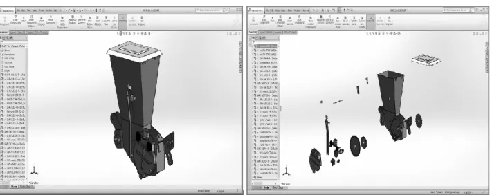
Figure 2.1 shows the 3D geometric model of the distribution device used in pneumatic machines for weeding plant
363
Figure 2.1 - 3D geometric model of the distribution device used in pneumatic machines for weeding plant sowing
RESEARCH RESULTS
After the stage of shaping the drive shaft configurations which is the main component part of the distribution device used in pneumatic machines for weeding plant sowing, we passed to the structural analysis stage with the help of the structural simulation application
SOLIDWORKS SIMULATION 2013,
which involved importing the geometry of the model created using the computer-aided engineering application (SolidWorks 2013), defining the material, defining the restrictions appropriate to meshes, running the program to calculate the Von Mises stress analysis, displacement, relative elongation, safety factor and visualizing the results in the form of diagrams.
Structural analysis using the CAD-CAE method involved the following operations:
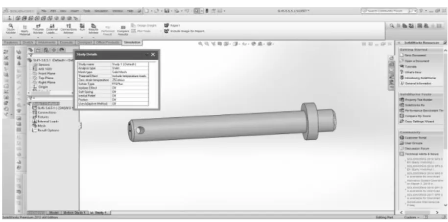
❖ selecting option static as analysis type, solid for mesh type and FFEPlus solver (fig. 3.1);
❖ selecting materials from the SolidWorks 2013 library and automatically assigning these
properties to each component part (as shown in Table 1);
❖ applying the appropriate stress. In accordance with the actual
operating mode (during
364
Figure 3.1 Option static as analysis type, solid for mesh type and FFEPlus solver
Properties of selected materials
Table 1
Material Yield
strength (σc) (N/mm2)
Traction limit (σr) (N/mm2)
Poisson’s ratio
Traction / compression
elastic modulus (E)
(N/mm2)
Traction / shear elastic modulus
(G) (N/mm2)
M1: S235JR 235 360 0,28 210000 79000
M2: E335 275 550 0,28 210000 79000
M3: C45 580 750 0,28 210000 79000
❖ applying the appropriate stress. In accordance with the actual operating mode (during exploitation) of the drive shaft, the simulation scenario was adapted accordingly. The stress was applied in the points corresponding to the operating mode shown in figure 3.2;
❖ using the meshing procedure, to decompose the model into discrete
elements (fig. 3.3). In general, a finite element model is defined by a network, which is completely realized from a geometric arrangement of elements and knots. Knots represent points, where features are calculated, such as displacements;
365
Figure 3.3 - 3D model discretized in a finite element network
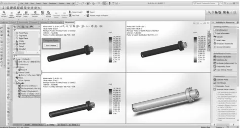
❖ running the analysis study to calculate the strain, safety factor and displacement, which is based on geometry, material, stress, restriction types and meshing type. After running the analysis studies, the results can be visualized for comparison (fig. 3.4)
The results of the analysis based on technical-economic criteria in choosing the metal material from which the drive shaft is manufactured are presented in table 2.
Fig. 3.4 - Sequence during the comparison of the studies and the results that appear on the screen in the form of the safety factor
Results of the analysis based on technical-economic criteria
Table 2
Name Unit of
measurement
Value
Material 1 S235JR
Material 2 E335
Material 2 C45
Safety factor - 0.81 0.98 2.1
Mass kg 0.9 0.9 0.9
Ratio: mass / safety factor - 1.1 0.91 0.42
Comparison of these indicators led to the choice of the optimum variant
366
CONCLUSIONS
The technical-economic indicator (material consumption per safety factor unit) proposed by the authors for analyzing the choice of the optimum
variant, which is represented by the mass/safety factor ratio, contributes to reducing the design validation time.
BIBLIOGRAPHY
1. Cârdei P. et al., Applications of finite
element structural analysis in the
microstructures field and their specific
issues, 2016, Proceedings of SGEM
Vienna Green International Scientific Conference, 2 - 5 November, Vienna, Austria, ISBN 978-619-7105-79-7, ISSN
1314-2704, DOI: 10.5593/
sgem2016HB63, Book 6 Vol. 3, pp. 11-18 2. Chapra, Steven C., 2012, Applied numerical methods with MATLAB for
engineers and scientists, ISBN
978-0-07-340110-2;
3. Saracoglu B. O., Gozlu Sitki, 2006, Identification of Technology Performance Criteria for CAD/CAM/CAE/CIM/CAL in
Shipbuilding Industry, Technology
Management for the Global Future -
PICMET 2006 Conference, ISSN:
2159-5100, Istanbul, Turkey
DOI:10.1109/PICMET.2006.2967;
4. Stoica L., Digital drawing in
architecture, Bucharest 2011, ISBN
978-973-0-10574-2;
5. Van der Auweraer, Herman; Anthonis, Jan; De Bruyne, Stijn; Leuridan, Jan, 2012, "Virtual engineering at work: the challenges for designing
mechatronic products”. Engineering with
computers.29 (3): 389–408.
doi:10.1007/s00366-012-0286-6;
6.***https://www.g2crowd.com/categories/ computer-aided-engineering-cae, 2019
ACKNOWLEDGEMENTS
This work was supported by a grant of the Romanian Research and Innovation Ministry, through Programme 1 – Development of the national research-development