Design And Simulation Of Interline Unified Power Quality
Conditioner (Iupqc) By Using Fuzzy Logic Controller
Sasanka Sowri T
M. Tech. Scholar, Dept of EEE
Bonam Venkata Chalamayya Engineering College Amalapuram
K.V.V. Satyanarayana
Asst. professor, Dept of EEE
Bonam Venkata Chalamayya Engineering College Amalapuram
Abstract:-This paper proposes anew connection for a unified power quality conditioner (UPQC) to improve the power quality of two feeders in a distribution system. The interline custom power devices named Interline Unified Power Quality Conditioner (IUPQC) is improved for various power quality disturbances and modeled in MATLAB/SIMULINK by using fuzzy logic controller. The developed topology can be used for simultaneous compensation of voltage and current imperfections in a multi bus/multi feeder system. The proposed IUPQC is designed for medium voltage level (11 kV) and effective Enhanced Phase Locked Loop (EPLL) with Fuzzy based control technique is used to detect and extract the PQ disturbances. The performance of Series Compensator of IUPQC is evaluated through extensive simulations for mitigating unbalanced voltage sags with phase jumps and interruption. The performance of Shunt Compensator of IUPQC is also tested for harmonic and reactive power compensation that are not investigated before in literature. It is verified that IUPQC which is connected to two feeders, can compensate current and voltage distortions successfully in these feeders according to the results obtained using MATLAB/SIMULINK.
I. INTRODUCTION
Power quality has become an important factor in power systems, for consumer and household appliances with proliferation of various electric/ electronic equipment and computer systems. The main causes of a poor power quality are harmonic currents, poor power factor, supply voltage variations, etc. In recent years the demand for the quality of electric power has been increased rapidly. Power quality problems have received a great attention nowadays because of their impacts on both utilities and customers. Voltage sag, swell, momentary interruption, under voltages, over voltages, noise and harmonics are the most common power quality disturbances.
In recent years, the use of nonlinear and electrically switched devices that draw non-sinusoidal currents in to the power systems have increased in utility and thus contribute to the degradation of power quality.
In recent studies, the concept of the multi converter based Interline Custom Power Devices are introduced. In an interline custom power device, two or more VSCs are connected back to- back through a common dc capacitor to two neighboring feeders. These devices can be of series-series, shunt-shunt or series-shunt type [5]. The main advantage of multi-feeder devices is that if any power quality problem occurs in one feeder, other adjacent feeder supplies power for compensating power quality problem. Therefore the multi-feeder PQ devices assure superior performance than single feeder PQ devices.
Unified Power Quality Conditioner (UPQC) consists of two IGBT based Voltage source converters (VSC), one shunt and one series cascaded by a common DC bus. The shunt converter is connected in parallel to the load. It provides VAR support to the load and supply harmonic currents. Whenever the supply voltage undergoes sag then series converter injects suitable voltage with supply[2]. Thus UPQC improves the power quality by preventing load current harmonics and by correcting the input power factor.
series VSC exist. The MC-UPQC system can be applied to adjacent feeders to compensate for supply voltage and load current imperfections on the main feeder and full compensation of supply voltage imperfections on the other feeder [1-15]. This study mainly focuses on modeling of IUPQC in MATLAB/SIMULINK simulation program. The proposed IUPQC is designed for medium voltage level (11 kV) and is developed for simultaneous compensation of voltage and current distortions in a multi-feeder system. An effective EPLL based control technique is used for IUPQC to detect and extract the PQ disturbances. The performance of proposed IUPQC system is evaluated through extensive case studies for mitigating harmonics, unbalanced voltage sags with phase jumps and interruption. The paper is organized in the following manner: System description, power circuit configuration and control strategy of proposed IUPQC are presented in section 2. Simulation results for different case studies are provided and discussed in section 3. Finally, conclusions of the study are given in section 4.
II. DESIGN OF IUPQC
Description of the proposed system
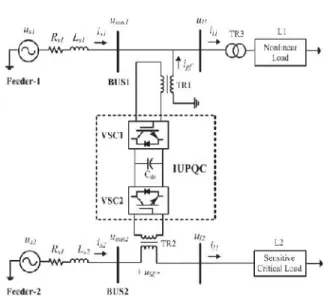
The IUPQC shown in Fig.1 consists of two VSCs (VSC-1 and VSC-2) that are connected back to back through a common energy storage dc capacitor. As shown in this figure, the feeder impedances are denoted by (Rs1, Ls1) and (Rs2, Ls2). It can be seen that
two feeders Feeder-1 and Feeder-2 are connected to two different substations that supply the system loads L1 and L2. The IUPQC is connected to two buses
BUS1 and BUS2 with voltages ubus1and ubus2. The
supply voltages are denoted by us1 and us2while load
voltages are denoted by ul1and ul2. Finally, two
feeder currents are denoted by is1and is2while load
currents are denoted by il1and il2.
The IUPQC consists of one series and one shunt converter which are connected to two adjacent feeders with being supplied from a common DC link. This topology provides power transfer between two adjacent feeders through DC link and it is very advantageous instead of conventional UPQC topology in a single feeder. In the proposed configuration, VSC1 is connected in parallel with load L1 at the end of Feeder-1 and VSC2 is connected in series with BUS2. The aims of the IUPQC are listed below:
Figure 1. Structure of IUPQC connected to distribution system
1) to compensate for reactive and harmonic components of nonlinear load current (il1);
2) to regulate the load voltage (ul2) against sag/swell, interruption and disturbances in the system to protect the sensitive/critical load L2.
In order to achieve these two goals, shunt VSC (VSC1) operate as a current controller while the series VSC (VSC2) operate as a voltage controller.
Configuration of Power Circuit
The structure of the IUPQC connected to a distribution system is shown in Fig. 1.consists of two VSCs (VSC1 and VSC2) that are connected back to back through a common dc capacitor (Cdc). In this topology VSC1 is connected in shunt to Feeder-1 while the VSC2 is connected in series with Feeder-2. The components of shunt compensator power circuit are DC link capacitor, three-phase inverter circuit and smoothing inductor (Lf, apf) as shown in Fig. 2.
Figure 2. The structure of Shunt VSC (VSC1)
The components of series compensator power circuit are DC link capacitor, inverter circuit, and inverter side filter and injection transformer as shown in Fig. 3.
Figure 3. The structure of Series VSC (VSC2)
Three single-phase H-Bridge voltage source inverter topology is used as series compensator in this study. Use of single-phase H-bridge PWM inverters makes possible the injection of positive, negative and zero sequence voltages. Thus, H-bridge PWM switched inverters provide superior performance to control asymmetries during unbalanced faults. The Series Compensator of IUPQC are connected to the distribution system in
series through single phase injection transformers. The injection transformer primary winding is connected with series compensator power circuit while its secondary winding is connected in series with the distribution line. The main purpose of the injection transformer is to boost the voltage supplied by the filtered VSC output to the desired level while isolating the Series Compensator circuit from the distribution network [12]. In this study, LC type inverter side filter is used to attenuate the high-order harmonics generated by the voltage source inverter. Inverter side filtering scheme has the advantage of being closer to the harmonic source thus high-order harmonic currents are prevented to penetrate in to the series injection transformer thus necessitates a lower rating on the injection transformer [13].
III. CONTROL SCHEME
A.EPLL
The IUPQC consist of Shunt and Series VSC which are controlled independently. The switching control strategy for series VSC and the shunt VSC are selected to be sinusoidal pulse width modulation (PWM) voltage control and hysteresis current control, respectively. In this study, simple and effective control algorithm is used to detect and extract the PQ disturbances. The algorithm is based on the nonlinear adaptive filter named Enhanced Phase Locked Loop (EPLL) presented in [14]. The reason of preferring EPLL is that it has simple structure than most preferred time based and frequency based methods and it has fast and accurate response with changing load conditions.
The EPLL is inherently adaptive and follows variations in amplitude, phase angle and frequency of the input signal. The EPLL is capable of
accurately
estimating the fundamental component of a polluted signal. The structure of the EPLL shown in Fig. 4, is simple and this makes it suitable for real-time embedded applications for software or hardware implementation [15]. The EPLL is formed from three main parts as shown in Fig. 4. These main parts are phase detector (PD), low pass filter (LPF) and voltage controlled oscillator (VCO). The EPLL receives the input signal u(t) and provides an on-line estimate of the following signals:
The synchronized fundamental component, y(t);
The amplitude, A(t) of y(t);
The difference of input and synchronized fundamental component, e(t);
The frequency deviation,�w(t);
Figure 4. The structure of EPLL
Mathematically, the EPLL is described by three main differential equations in time domain:
( ) = ∫ ( ). ( ). . (1)
∆ = ∫ ( ). sin + ( ). . (2)
( ) = − 2⁄ + [ ( ). ( ). + ∆
+ ]
(3)
The error signal, e (t) = u (t) - y (t) , is the total distortion signal of the input and can be expressed as a continuous time;
( ) = ( ) − ( ) ∫ ( ). ( ). . (4)
Functions of the shunt VSC (VSC1) are to compensate for the reactive component of load L1 current (il1), to compensate for the harmonic components of il1 and to regulate the voltage of the common dc capacitor (Vcap). The controller algorithm of shunt compensator is formed from the harmonic current extraction, hysteresis current controller, DC link voltage controller and reactive power control as shown in Fig. 5.
Shunt Compensator control system measures the load voltages (ul1), dc capacitor voltage (Vcap), load currents (il1) and injected currents (IAPF). The controller processes the measured values and generates the required compensation signals. These signals are then compared in hysteresis controller and the required gate signals are generated.
Figure 5. Control Scheme for Shunt Compensator
When the distorted current or voltage signal is applied to EPLL, the harmonics and inter harmonics of distorted signal (Ihar) can be obtained from the e(t) signal of EPLL. DC link voltage control is achieved by using PI controller. The input of the PI controller is the error between the actual capacitor voltage Vcap and its reference value Vcap, ref. In order to keep DC link voltage at a constant level, shunt compensator must draw active power by drawing current (Icap) in phase with line voltage. To draw a current in the same phase with system voltage, phase information of system voltage (�Vload) must be known. This can be achieved by using EPLL. With using phase of system voltage, DC link control reference current signal is created by multiplying the PI controller output and sine wave created by phase information of system voltage.
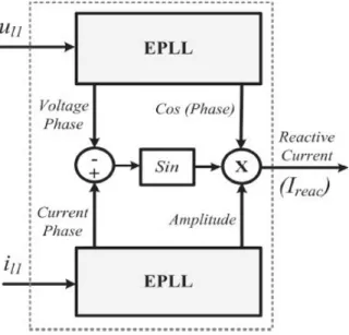
Figure 6. Proposed reactive-current extraction unit
signals. The top portion of the unit is used for voltage and the bottom portion is used for current signal processing. The link between the two parts is to calculate the fundamental reactive current component (Ireac).
Figure 7. Control Scheme for Series compensator
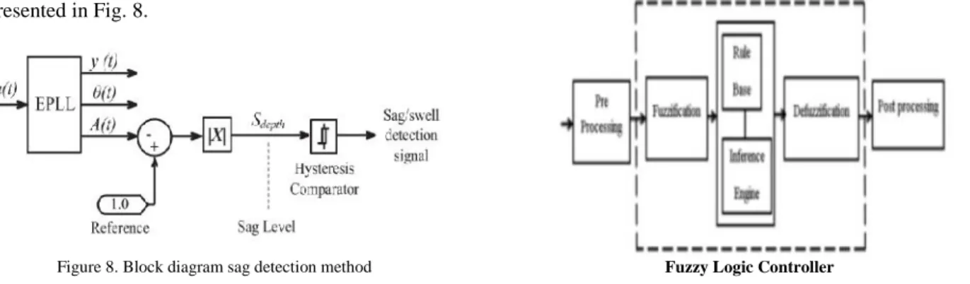
The main aim of the series VSC (VSC2) is to mitigate voltage sag/swell and interruption in Feeder-2. The control system of series compensator consists of sag/swell detection, reference voltage extraction and gate signal generation as shown in Fig. 7.
Simple and effective control algorithm is proposed for both sag/swell detection and reference voltage generation in this paper. The algorithm is based on the EPLL that extracts and directly provides the amplitude A(t), phase angle ( )and fundamental component A(t) cos ( )of the input signal for each phase independently. With the proposed method, the controller is able to detect balanced, unbalanced and single phase voltage sags/swells without an error. In this method, three EPLLs are used to track each of the three phases.
In the EPLL, the measured phase supply voltages are converted to per unit value. A(t) gives the amplitude of the tracked signal u(t). If there is no sag or swell, A(t) signal is obtained as continuous 1 pu. By subtracting the A(t) signal from the ideal voltage magnitude (1 pu), the voltage sag/swell depth (Sdepth) can be detected. The comparison of this value with the limit value of 10% (0.1 pu) gives information whether a fault occurred or not [16]. The voltage sag/swell detection based on EPLL method is presented in Fig. 8.
Figure 8. Block diagram sag detection method
Reference voltage Verror is calculated according to voltage injection strategy by using magnitude A(t), the output y(t) and phase ( )signals extracted with EPLL. In this study, Pre-Sag Compensation method is used as voltage injection strategy. Pre-Sag Compensation (PSC) method tracks supply voltage continuously and if it detects any disturbances in supply voltage it will inject the difference voltage (Verror, presag) between the sag or voltage at point common coupling (PCC) and pre-fault condition, so that the load voltage can be restored back to the pre-fault condition.
If sag is accompanied by a phase jump, PSC method offers better performance by compensating voltage sags in the both phase angle and amplitude for sensitive loads [17]. Other voltage injection strategies such as in-phase, phase-advance and minimum energy injection compensation methods may not prevent the phase jump of the load voltage at the starting and ending instants of the sag compensation period [18].
PWM switching method is used as gate signal generation for series converter. The switching pulses are generated by comparing the reference voltage compensation signal Verror with a fixed frequency carrier triangular wave.
B. FUZZY LOGIC CONTROL:
In FLC, basic control action is determined by a set of linguistic rules. These rules are determined by the system. Since the numerical variables are converted into linguistic variables, mathematical modeling of the system is not required in FC. The FLC comprises of three parts: fuzzification, interference engine and defuzzification. The FC is characterized as; i. Seven fuzzy sets for each input and output. ii. Triangular membership functions for simplicity. iii. Fuzzification using continuous universe of discourse. iv. Implication using Mamdani‟s „min‟ operator. v. Defuzzification
using the „height‟method.
Fuzzification
Membership function values are assigned to the linguistic variables, using seven fuzzy subsets: NB (Negative Big),NM(Negative Medium), NS (Negative Small), ZE (Zero), PS (Positive Small),PM(Positive Medium) and PB (Positive Big). The partition of fuzzy subsets and the shape of membership function adapt the shape up to appropriate system. The value of input error E(k) and change in error CE(k) are normalized by an input scaling factor [11]and[12].
TABLE1. FUZZY RULES
e
∆
NB
NM
NS
ZE
PS
PM
PB
NB
NB
NB
NB
NB
NM
NS
ZE
NM
NB
NB
NB
NM
NS
ZE
PS
NS
NB
NB
NM
NS
ZE
PS
PM
ZE
NB
NM
NS
ZE
PS
PM
PB
PS
NM
NS
ZE
PS
PM
PB
PB
PM
NS
ZE
PS
PM
PB
PB
PB
PB
ZE
PS
PM
PB
PB
PB
PB
In this system the input scaling factor has been designed such that input values are between -1 and +1. The triangular shape of the membership function of this arrangement presumes that for any particular input there is only one dominant fuzzy subset. The input error E(k) for the FLC is given as
( ) = ( ) ( )
( ) ( ) ( ) = ( ) − ( − 1)
Fig. (a)
Fig.(b)
Fig.9 (a) & (b) Membership functions
Inference Method
Several composition methods such as Max–Min and Max-Dot have been proposed in the literature. In this paper Min method is used. The output membership function of each rule is given by the minimum operator and maximum operator. Table 1shows rule base of the FLC
Defuzzification
As a plant usually requires a non-fuzzy value of control, a defuzzification stage is needed. To
compute the output of the FLC, „height‟ method is used and the FLC output modifies the control output. Further, the output of FLC controls the switch in the inverter.. In order to control these parameters, they are sensed and compared with the reference values. To achieve this, the membership functions of FC are: error, change in error and output as shown in Figs. (a), (b). In the present work, for fuzzification, non-uniform fuzzifier has been used. If the exact values of error and change in error are small, they are divided conversely and if the values are large, they are divided coarsely.
= −[∝ + (1−∝) ∗ ]
Where α is self-adjustable factor which can regulate the whole operation. E is the error of the system, C is the change in error and u is the control variable. A large value of error E indicates that given system is not in the balanced state. If the system is unbalanced, the controller should enlarge its control variables to balance the system as early as possible. One the other hand, small value of the error E indicates that the system is near to balanced state. Overshoot plays an important role in the system stability. Less over shoot is required for system stability and in restraining oscillations. C in (12) plays an important role, while the role of E is diminished. The optimization is done
by α. The set of FC rules is given in Table 1.
IV.SIMULATION RESULTS
TABLE II. SYSTEM PARAMETERS
System parameters Values Fundamental Frequency (f)
Voltage Source ( )
Voltage Source ( )
Feeder-1 ( + 2 )
Feeder-2 + 2 )
Nonlinear load (L1)
Sensitive/Critical Load (L2)
DC Link Capacitor ( )
DC Link Capacitor Voltage
( )
Coupling Transformer TR1)
Injection Transformer (TR2)
Power Transformer (TR3)
50Hz
11 Kv (L-L,rms), phase angle0
11 Kv (L-L,rms), phase angle0 Impedance:0.0015+j0.0785Ω Impedance:0.0015+j0.0785Ω A three- phase diode bridge
rectifier that supplies a load of
100+j125.66Ω
150.0+j23.56Ω
40 mF
1700 V
2 MVA, 11/1kV Δ/Y, Uk:5% 2 MVA, 1.2/8.0 kV,
10% Leakage reactance 2 MVA, 11/6.3 kV Δ/Δ, Uk:10%
Harmonic Distortion on Feeder-1
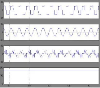
This case presents how VSC1 overcomes the load current harmonics with the proposed control algorithms. A three phase diode bridge rectifier is used as a harmonic current producing load. The nonlinear load contains lower and higher order harmonics with a total value of 25.08% THD before compensation.
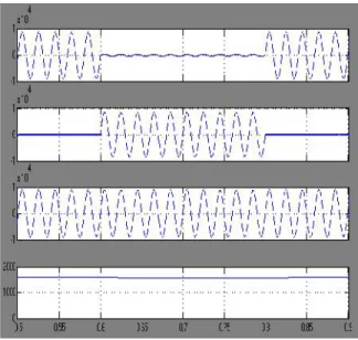
Figure 10. Nonlinear load current, compensating current, Feeder1 current and dc link capacitor voltage for Case A
VSC1 eliminates the load current harmonics by injecting current that cancel harmonic currents of nonlinear load as shown in Fig. 10. The waveforms indicate the nonlinear load current (Il1), its corresponding compensation current injected by VSC1 (ipf), compensated Feeder-I current (iS1) and the dc link capacitor voltage (Vcap) of Phase-A respectively. The results show that a successful reduction in harmonics of the nonlinear load current (il1) is obtained. A nonlinear load current with 25.08% THD is reduced to less than 5%. The PI controlled dc-link capacitor voltage is nearly kept at 1.7 kV.
Voltage Sag on Feeder-2
In this case, single line-to-ground unbalanced fault is considered, since it is most likely to occur in 70% of among all voltage sags in a distribution system [16]. 35% Single line-to-ground fault with 47.64o phase angle jump is investigated which occurs on Phase-A of BUS2 voltage between 0.3 s < t < 0.5 s. The sensitive/critical load (L2) voltage is not affected by voltage sag with the help of series compensator (VSC2). Fig. 11 shows the BUS2 voltage (ubus2), series compensating voltage (uSE), L2 load voltage (ul2) and dc link capacitor voltage (Vcap).
Upstream Fault on Feeder-2
In this case study, the performance of VSC2 for upstream fault (interruption) mitigation on Feeder-2 is investigated.
Single phase (L-G) interruption occurs on Phase-A of BUS2 voltage between 0.6 s < t < 0.8 s, and 25.27o phase angle jump occurs during the interruption. The sensitive/critical load (L2) voltage is not affected by voltage sag with the help of series compensator (VSC2). Fig. 12 shows the BUS2 voltage (ubus2), series compensating voltage (uSE) and L2 load voltage (ul2) and the dc link capacitor voltage (Vcap).
Figure 12. BUS2 voltage, series compensating voltage, load (L2) voltage and dc link capacitor voltage for Case C
V. CONCLUSION
This paper proposes an improved IUPQC topology for simultaneous compensation of voltage and current in adjacent feeders has been proposed. An effective EPLL with fuzzy based control technique is used for IUPQC to detect and extract the PQ disturbances in multi-feeder system. Each phases of Series and Shunt Compensator are investigated independently with EPLL based fuzzy controller. The performance of proposed IUPQC system is evaluated through extensive simulations for mitigating harmonics, unbalanced voltage sags with phase jumps and interruptions. The results of simulations show its effectiveness in handling these PQ issues, so that smooth and clean power flow to the loads.
REFERENCES
[1] h. R. Mohammadi, a. Y. Varjani and h. Mokhtari,
“multiconverter unified power-quality conditioning system: mc-upqc,” ieee transactions on power delivery, vol. 24, no. 3, july 2009.
[2] m. D. Vilathgamuwa, d. Wijekon, s. Choi, “a
novel technique to compensate voltage sags in multiline distribution system – the interline dynamic
voltage restorer,” ieee transactions on industrial
electronics, vol.53, no:5, pp.1603-1611, 2006.
[3] a. K. Jindal, a.ghosh, a. Joshi, “interline unified power quality conditioner,” ieee transactions on power delivery, vol. 22, no: 1, january 2007.
[4] h. Kian, c. Yun, l. Ping, “model-based h�control of a unified power quality conditioner,” ieee transactions on industrial electronics, vol.56, no:7, pp.2493-2504, 2009.
[5] a.k. jindal, a. Ghosh, a. Joshi and a. M. Gole,
“voltage regulation in parallel distribution feeders using ivolcon,” power and energy society general
meeting - conversion and delivery of electrical energy in the 21st century, ieee, 2008.
[6] d. M. Vilathgamuwa, h. M. Wijekoon and s. S.
Choi, “interline dynamic voltage restorer: a novel and
economical approach for multiline power quality
compensation,” ieee transactions on industry
applications, vol. 40, no. 6, 2004.
[7] m. R. Banei, s. H. Hosseini and g. B gharehpetian,
“inter-line dynamic voltage restorer control using a
novel optimum energy consumption strategy,”
simulation modelling practice and theory, vol. 14, elsevier, 2006.
[8] h. R. Karshenas and m. Moradlou, “design
strategy for optimum rating selection in interline
dvr,” canadian conference on electrical and computer
engineering, ieee, 2008.
[9] c. N. Ho and h. S. C. Chung, “implementation and
performance evaluation of a fast dynamic control scheme for capacitor-supported interline dvr” ieee transactions on power electronics, vol. 25, no. 8, 2010.
[10] m. Moradlou and h. R. Karshenas, “design
strategy for optimum rating selection of interline
dvr,” ieee transactions on power delivery, vol. 26, no.
1, 2011.
[11] a. K. Jindal, a. Ghosh and a. Joshi, “power quality improvement using interline voltage
controller,” iet generation transmission &
distribution, vol.1, no. 2, 2007.
[12] k. Perera, a. Atputharajah, s. Alahakoon and d.
Salomonsson, “automated control technique for a
single phase dynamic voltage restorer,” proceedings of the international conference on information and automation, colombo, sri lanka, 2006.
[13] s. Choi, b. H. Li, d. Vilathgamuwa, “design and
analysis of the inverter-side filter used in the dynamic
[14] m. Karimi-ghartermani and m. R. Iravani, “a nonlinear adaptive filter for online signal analysis in
power systems applications,” ieee transactions on
power delivery, vol. 17, pp. 617-622, 2002.
[15] m. Karimi ghartemani, m. R. Iravani and f.
Katiraei, “extraction of signals for harmonics,
reactive current and network-unbalance
compensation,” ieee proceedings generation, transmission and distribution, vol. 152, no. 1, pp. 137-143, 2005.
SASANKA SOWRI T currently pursuing his M.Tech in Power Systems from Bonam Venkata Chalamayya Engineering College, Amalapuram, Andhra Pradesh, India affiliated to JNTUK University, Kakinada. He has done his B.Tech degree from Bonam Venkata Chalamayya Engineering College, Odalarevu affiliated to JNTUK University, Kakinada Andhra Pradesh, India and his fields of interest include Power Systems.
K.V.V. SATYANARAYANA presently working as