Abstract—Fracture apertures may decrease or increase by different mechanical and chemical mechanisms when the fractures are subject to stress and flow. A model is presented to describe evolution of fracture aperture mediated by dissolution and precipitation. The model accounts for the fact that dissolved minerals carried by flowing water along the fracture can not only diffuse into and out of the adjacent rock matrix but also at first diffuse into the stagnant water zone existing in part of the fracture plane and then from there into and out of the rock matrix adjacent to it. This simple model allows us to gain some insights into which processes and mechanisms have the larger impact on the fracture aperture under different circumstances. The analytical solution in Laplace domain is used to study fracture closure/opening rate in a pseudo steady state procedure. It is found that the times involved for any changes in fracture aperture are very much larger than the times needed for concentrations of dissolved minerals to reach steady state in the rock matrix, the stagnant water zone and the flow channel. Moreover, it is shown that diffusion into the rock matrix, which acts as a strong sink or source for dissolved minerals, clearly dominates the rate of concentration change and consequently the rate of evolution of the fracture aperture.
Index Terms—Channeling, fracture aperture, modeling, rock matrix diffusion.
I. INTRODUCTION
Rock fractures are dynamic and may close or open due to mechanical and chemical effects which may considerably influence water flow and solute transport in the fractured rocks [1], [2]. Mechanically mediated changes occur faster compared to chemically mediated changes, which are time-dependent and take longer time to reach a steady state [3]. Aperture closure/opening over time in stressed natural fractures has been experimentally observed [4], [5], however the main causes have still been under discussions. Evolution of fracture permeability has also been studied theoretically and modelled by accounting for pressure dissolution and precipitation [6]˗[15]. The involved mechanisms in modelling are basically that the mineral tends to dissolve where the higher stress is applied and will precipitate where the stress is lower.
In fractured rocks, the two surfaces of a fracture are in contact with each other in some asperities but are open in other locations. At the contact asperities, the local stress is higher than the average stress on the whole fracture since stress is concentrated in a small part of entire fracture
Manuscript received January 25, 2016; revised March 27, 2016. The authors are with the Department of Chemical Engineering and Technology, Royal Institute of Technology, Stockholm, Sweden (e-mail: [email protected]).
surface. At points where the local stress is much larger than the grain strength, mechanical crushing may occur. This will produce small mineral fractions within the fracture. When fractured rocks contain water, the minerals may dissolve if the water is not saturated. At contacting asperities with high concentrated stress the solubility of minerals is higher than at fracture voids. The minerals, then, tend to dissolve there and precipitate where the stress is lower. This, so-called “pressure dissolution” process may lead to closure of the fracture after some time. In contrast, “free-face dissolution” at fracture voids with under-saturation fluid may result in local fracture widening [16].
Another phenomenon that contributes to changes in solute concentration, which in turn affects dissolution and precipitation is dissolution of small mineral fragments which have larger solubility than large minerals [17]. The small dissolving fragments increase the concentration in the fracture and as a result decrease the driving force for pressure dissolution. This effect has only been studied recently by Neretnieks [15] even though the formation of these small fragments has been modeled [3].
Furthermore, any advective flow through the fracture that can carry in or away solute and even colloidal mineral fragments would increasingly complicate the situation.
Yasuhara et al. [18] showed that the water flow rate through a fracture could affect the fracture closure rate.
In addition to advection through the flow channel, the dissolved minerals can also diffuse into the adjacent porous rock matrix. Matrix diffusion has been found to be an important transport process in fractured crystalline rocks [19], [20]. It has been used in modeling solute transport in fractured crystalline rocks [21], [22] and is a very important process that retards contaminant transport in fractured rocks. Recently Neretnieks [15] showed that matrix diffusion effect is also very important for chemically mediated closing of fractures in crystalline rocks.
Moreover, numerous field observations show that ground water is flowing only in a small part of a conductive fracture to form one or more so-called “flow channels” [23]. We call the regions with much less flow, “stagnant water zones”. It is expected that these regions contain the stressed crystals, whereas in the channels where water flows there are few, if any, stressed crystals. Until recently, Neretnieks [24] and
Mahmoudzadeh et al. [25] took the influence of the stagnant water zone in fracture plane into account. They found that solute diffusion into the stagnant water zone adjacent to the flow channel can significantly contribute to the retardation of solute. In this paper, it will be shown that stagnant water zones in the fracture plane can also affect fracture closure in crystalline rocks. This effect, which has not been addressed
Evolution of Fracture Aperture under Combined Effect of
Stress and Flow
yet, would be considered together with matrix diffusion effect in a water flowing fracture.
II. CONCEPTUAL MODEL
To highlight the most important phenomena affecting on fracture evolution, we try to develop a reasonable simplifying model by combining all stressed areas and all free-face areas. This includes the mineral grains in the flowing part of the fracture as well as those in the porous rock matrix and in stagnant water zones in the fracture. Fig. 1 illustrates the conceptualized model wherein the flow is assumed to take place between two parallel surfaces separated by 2bf, forming a rectangular channel of width
2Wf, with constant mean velocity, u. The stagnant water
zone next to the flowing fracture is similarly conceptualized as another rectangular of 2bs aperture and 2Ws width. It is
assumed that stressed and unstressed crystals are lying in the stagnant water zone adjacent to the flow channel. The rock matrix is porous and the mineral grains there can also dissolve or act as precipitation surfaces depending on local over- or under-saturation. The model accounts for only free-face dissolution in the flow channel but for both pressure dissolution and free-face dissolution in stagnant water zone. The model also accounts for the fact that material dissolved by either pressure or free-face dissolution can directly diffuse from the flowing or stagnant water into and out of the adjacent rock matrix, in addition to advection through the flowing fracture and diffusion into the stagnant water zone.
Fig. 1. Flow in a channel in a fracture where crystals are stressed in the stagnant water zone in the fracture plane.
In order to devise a model that can be solved analytically, a first step is to consider the case when the size of stressed surface and free-face surface is constant in time. The strength of the analytical approach is that the rates of different competing processes can be summarised in a limited number of parameter groups. The analytical model will be used in a pseudo steady state, PSS, procedure to study the rate of fracture closure/opening due to stress and the conditions that may lead to the growing of the flow channel aperture.
III. MATHEMATICAL MODEL
We start from a case with constant aperture in flow channel and stagnant water zone. According to the coupled 1-D approach, the system shown in Fig. 1 can be identified as four subsystems; flow channel, stagnant water zone, the rock matrix adjacent to the flow channel and rock matrix adjacent to the stagnant water zone, for which equations of continuity can be formulated individually. Transport equations will be then coupled at boundaries between subsystems.
A. Transport in the Flow Channel
The transport equation for the aqueous concentration in the flow channel, Cf, can be written as
0 0 ,1
z pf f pf pf y s f ws f s f F eq f pf f fz
C
b
D
y
C
W
D
b
b
C
C
b
k
x
C
u
t
C
(1) with
RT
V
C
C
F m eq F eq 1 1 , ,exp
(2)where Ceq,1 and Ceq,F are the equilibrium concentrations of
the mineral at the reference stress σ1 1 bar and at the stress
σF the pressure applied at free faces, respectively.
The initial condition is
F eq
f
t
x
C
C
(
0
,
)
, (3)and the boundary condition is
in f
f
t
x
C
C
(
,
0
)
, (4)In equation (1), x, y and z are coordinates along the flowing fracture, into the stagnant water zone and into the rock matrix adjacent to the flow channel, respectively. k is the mass transfer coefficient which is the same constant in all four subsystems. A complete list of symbols and units is given in notation section.
B. Transport in the Stagnant Zone
Assuming that diffusion in the direction parallel to the flow is negligible, the transport equation for aqueous concentration in the stagnant water zone, Cs, is given by
0 1 , , 2 2 1 1 1 1 4 1 z ps s ps ps s P eq s s F eq s ps y s ws s z C b D C C b k C C k b L y C D t C
(5) with
RT
V
C
C
P m eq P eq 1 1 , ,exp
(6)where Ceq,P is the equilibrium concentrations of the mineral
the crystals [26]. The ratio
is a fraction of wetted surface in stagnant water zone representing all lumped stressed surfaces of crystals.The initial condition is
F eq
s
t
y
C
C
(
0
,
)
, (7)and the boundary conditions are
f
s
t
y
C
C
(
,
0
)
(8) and0
2
WS
y s
y
C
(9)
The transport processes in the flow channel and in the stagnant water zone are coupled through equation (8) describing the continuity of the aqueous concentration of dissolved material.
C. Transport in the Rock Matrix Adjacent to the Flow Channel
The 1-D transport equation for the concentration in the pore water in the rock matrix adjacent to the flow channel is
eqF pf
f pf
pf pf
pf pf
C
C
ka
z
C
D
t
C
, 2
2
1
(10)
where
a
f is specific surface of dissolving crystals in therock matrix adjacent to the flowing fracture. The initial condition is
F eq
pf
t
z
C
C
(
0
,
)
, (11)and the boundary conditions are
f
pf
t
z
C
C
(
,
0
)
(12)and
0
f
z pf
z
C
(13)
D. Transport in the Rock Matrix Adjacent to the Stagnant Water Zone
Similar to equation (10), transport equation for concentration in the pore water in the rock matrix adjacent to the stagnant water is
eqF ps
s ps
ps ps
ps ps
C
C
ka
z
C
D
t
C
, 2
1 2
1
(14)
The initial condition is
F eq
ps
t
z
C
C
(
0
,
1)
, (15)and the boundary conditions are
s
ps
t
z
C
C
(
,
1
0
)
(16)and
0
1
1
s
z ps
z
C
(17)
IV. FRACTURE CLOSURE RATE
The governing equations can be solved by applying Laplace transformation approach [27]. This approach removes the time variable leaving a system of ordinary differential equations, solution of which yields aqueous concentration as a function of space variable. One shall begin with the Laplace transformed equations in the rock matrices and continue with equations in the stagnant water zone and the flow channel. The analytical solution for concentration obtained in the Laplace space is then used to study evolution of the fracture aperture in a pseudo-steady-state, PSSA, procedure.
In our model we assume that crystals are cubs of size Lz
and Ly and have two stressed sides parallel to the fracture
surfaces. The closure rate of stagnant zone will be determined by the size of the stressed shrinking crystal assuming that wall is inert where the crystal is in contact. Therefore, by neglecting the very thin water film between the stressed crystal and the fracture wall, and given that PSSA is applicable, the fracture closure rate in the stagnant water zone can be approximated by the rate of change of Lz
dissolving from two sides as,
eqP s
m z
s
V
k
C
C
dt
dL
dt
db
,2
1
(18)
The fracture aperture, which determines the hydraulic conductivity, will close with the rate that the stressed crystals shrink but will on the other hand grow with the rate that the free-face dissolution determines. The free-face dissolution in the stagnant zone will not influence the closure of the fracture in the flow channel. The evolution of fracture aperture in the flow channel can be determined by
eqF f
m y s f
C C k V dt
db dt db
, 0
(19)
There may be free-face dissolution or precipitation depending on the driving force direction, and the aperture as a whole may close if the stressed crystals in the stagnant zone dissolve faster than the free-face crystals of the fracture wall. The aperture changes differently at different locations along the flow path. The rate of change of aperture varies with time and can be approximately followed using the PSSA. We will, however, only consider a series of snapshots in time in this paper to follow the aperture evolution.
V. SIMULATION AND DISCUSSION
TABLEI:DATA USED IN EXAMPLES
Notatio
n
Valu
e
Notation Value
bf (m) 1e-4 Dpf&Dps (m2/s) 5.2e-10
bs (m) 1e-4 ε(%) 30
x (m) 50 T (K) 353
Wf (m) 0.1 k+1 (mol/m2/s) 4.78e-12
Ws (m) 0.5 Ceq,1 (mol/m3) 5.57e-4
u (m/yr) 5 σ´ (MPa) 8.1
δf (m) 1 α (-) 0.11
δs (m) 1 Mcrystal(g/mol) 60.01
Dw(m2/s
)
1e-9 ρcrystal (g/m3) 2.65e6
The geometrical and physical properties of the flow channel, the stagnant water zone and the rock matrix are representative of those from field observations [28], [29] whereas the effective diffusivity is calculated according to Archie’s law, Dwε0.6. The solubility related data are taken
from [30], and the other data have been chosen to resemble the condition of water-saturated sandstone rock matrix with 30% porosity hosting a nuclear waste repository in about 500 m depth. The grains in the matrix has the same size of stressed crystal which is initially the same as aperture in stagnant zone.
We start from a simplified case where there is no flowing water i.e. the system consists only of stagnant water zone and its adjacent rock matrix. This system resembles the model studied by Neretnieks [15] where the oversaturated solute from the stressed crystal diffuses out to the surrounding water from which the solute re-precipitates on the unstressed surfaces of the same crystal or diffuses into the porous rock matrix to precipitate on other crystals there. That study showed that the sink due to matrix diffusion is important and affect crystal dissolution and fracture aperture evolution. We account here for combined effect of pressure dissolution, free-face dissolution/precipitation and matrix diffusion on the dissolution rate of stressed crystals. Using parameter values in his study with 30% porosity of rock matrix, our pseudo steady state approximation is able to reproduce the shrinking rate of crystal obtained numerically by Neretnieks [15]. This is illustrated in Fig. 2.
Fig. 2. Comparing shrinking rate of crystal obtained by analytical solution at y = 3.3 mm and by numerical solution given by Neretnieks (2014).
The power of the analytical approach is that it gives us some insights into which processes or mechanisms have larger impact on fracture closure rate since the rate of different competing processes can be summarized in a number of characteristic parameters.
Another case is considered where there is flow but no stagnant water zone in the fracture plane, i.e., Ws= 0, and
therefore our system consists only of the flow channel and the adjacent rock matrix. There are no shrinking stressed crystals in the flow path in the model that contribute to the dissolution of quartz. Only the free-face dissolution and the dissolution inside the rock matrix are the sources of dissolved silica found in the flowing water. The contribution of dissolved silica from any stressed crystal would be less than 1% of that due to diffusion out from the rock matrix as found earlier [15].
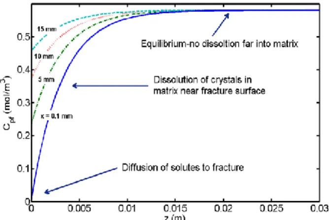
The pore water concentration profile in the rock matrix at different distances downstream in the flow channel, shown in Fig. 3, can be divided into three parts to illustrate the dominating mechanism in each region. As mentioned in the figure, at the surface of flow channel, i.e., at z = 0, the dissolved minerals diffuse to/from the flow channel. At very short distances into the rock matrix, the crystals in the rock matrix near to the fracture surface would dissolve on their free faces; and further on into the matrix where equilibrium has reached there is no dissolution of minerals into the matrix. In this part, the rock matrix is then not affected by what happens in the flow channel.
Fig. 3. Concentration profile in the pore water in the rock matrix adjacent to the flow channel with Cf,in = 0 and at t = 1 yr.
Fig. 4. Aperture evolution with Cf,in = 0 at x = 1 m and y = 1m.
account for the fact that the stress applied on stressed faces changes over time because the stressed area changes by free-face dissolution/precipitation of crystals on their unstressed surfaces. In a variable fracture, the stress decreases considerably if either the stressed surface grows or more stressed crystals get involved.
The closure/opening rate of fracture can be obtained by equations given in Section IV. At the inlet of flow channel with an incoming fresh water, the free-face crystals of the fracture wall would dissolve with a rate of 1.12e-16 m/s (3.5e-09 m/yr). This indicates that the channel aperture would grow by 0.1 mm in about 15,000 yr by free-face dissolution, unless the fracture in the stagnant water zone closes and brings the flow channel mechanically down with it. Therefore, the flow channel aperture increases due to free-face dissolution at least near the fresh water inlet. However, further downstream where the concentration has reached equilibrium the fracture would close slowly everywhere due to the dissolution of the shrinking stressed crystals in the stagnant water zone. The rate of change of the fracture aperture has been demonstrated in Fig. 4. It is seen that fracture in the stagnant water zone will completely close in about 15,000 yr, and simultaneously fracture aperture in the flow channel will decrease from 0.2 mm to 0.1001 mm. The aperture of flow channel will close with the rate that the stressed crystals shrink but will grow with the rate that the free-face dissolution of crystals of the fracture wall determines. The solubility of crystals in the stressed faces increases by nearly a factor of two compared to the solubility in the free-face sides as well as those crystals in the rock matrix and the fracture wall. Therefore, the fracture aperture would be mainly determined by stress-induced dissolution of crystals in the stagnant water zone. It indicates that the fracture aperture in the flow channel will essentially decrease by mechanical effects resulting from pressure dissolution of stressed crystals in the stagnant water zone.
VI. CONCLUSION
In this study, a model is developed to study closure rate of a fracture in fractured rocks. It accounts for advection through the fracture, diffusion into the rock matrix as well as into the stagnant water existing in the fracture plane, pressure dissolution and free-face dissolution of minerals in the fracture. Analytical expressions for the Laplace-transformed concentrations in the flow channel, stagnant water zone and their adjacent rock matrices have been derived. These analytical solutions are then used in a pseudo steady state approach to get closure/opening rate of fracture due to stress or the conditions that may cause growing of the fracture aperture. It should be noted that our analytical approach is for linear processes and nonlinear processes have to be studied in a different way which is not in the scope of the current paper. This rather simple model gives us some insights into which processes and mechanisms have the larger impact on the fracture aperture under different circumstances. The power of the analytical approach is that the rates of different competing processes can be
summarized in a limited number of characteristic terms. Some simulations have performed to illustrate contribution of different processes or mechanisms in closure rate of fracture. It is found, in the cases studied, that the times involved for any changes in aperture are very much larger than the times needed for concentrations to reach steady state in the rock matrix, the stagnant water zone and the flow channel. Furthermore, the results show that diffusion into the rock matrix that acts as a sink or source for dissolving minerals, strongly dominates the rate of concentration change in the fracture and as a result the fracture closure/opening rate. The pressure dissolution is the rate limiting process and is used to estimate the closing rate of fracture. For the condition considered, it is shown that the described processes would have a significant impact on the fracture aperture, and therefore they should be considered in safety and performance assessment of repositories for spent nuclear waste. This is an important issue not only for the radioactive waste repositories, but can be also used as a technique in other areas such as geological storage of CO2
or geothermal heat extraction from hot dry rock.
NOTATION
af / as Specific surface of dissolving crystals in
rock matrix adjacent to the flowing fracture/the stagnant water zone (L-1)
bf / bs Half aperture of the flow channel/stagnant
water zone (L)
Ceq,1 Equilibrium solubility of mineral at
reference stress 1 bar (ML-3)
Ceq,F / Ceq,P Equilibrium solubility of mineral at stress
σF/at effective stress σ´P (ML -3
)
Cf / Cs Concentration in the flow channel/stagnant
water zone (ML-3)
Cpf / Cps Pore water concentration in the rock matrix
adjacent to the flow channel/adjacent to the stagnant water zone (ML-3)
Def / Des Effective diffusivity in the rock matrix
adjacent to the flow channel/adjacent to the stagnant water zone (L2T-1)
Dpf / Dps Pore diffusivity in the rock matrix adjacent
to the flow channel/adjacent to the stagnant water (L2T-1)
Dw Water Diffusivity (L2T-1)
Ff Ratio of flow-wetted surface of the flow
channel to volumetric water flow rate (TL-1) Fs Ratio of the stagnant-water-wetted surface
to the diffusion conductance of the stagnant water zone (TL-1)
kdiss Dissolution rate constant at reference stress
1 bar (LT-1)
Mcrystal Molar mass of minerals, silica (MN-1)
N Ratio between the diffusion rate into the stagnant water zone and the mass flow rate through the channel (-)
s Laplace transform variable (T-1)
t Time (T)
Vm molar volume of silica (L3N-1) Wf Half width of the flow channel (L) Ws Half width of the stagnant water zone (L)
α Fraction of wetted surface in stagnant water demonstrating all lumped stressed surfaces
δf / δs Thickness of the rock matrix adjacent to
flow channel/adjacent to the stagnant water (L)
εpf / εps Porosity of the rock matrix adjacent to the
flow channel/adjacent to stagnant water (-)
ρcrystal Density of crystal, silica (ML-3)
σF -1T-2)
σ´ Effective stress (ML-1T-2)
σ´P Effective stress applied on the crystal
stressed faces (ML-1T-2)
τFdiss,f Characteristic time of free-face dissolution
in the flow channel (T)
τFdiss,s Characteristic time of free-face dissolution
in stagnant water zone (T)
τPdiss,s Characteristic time of pressure dissolution
in stagnant water zone (T)
τf / τs Characteristic time of advection/ diffusion
through the stagnant water zone (T)
φ Ratio of the contact area between stressed crystals and fracture surface to the total cross-sectional area normal to the applied total stress (-)
REFERENCES
[1] L. Jing, K. B. Min, A. Baghbanan, and Z. Zhao, “Understanding coupled stress, flow and transport processes in fractured rocks,”
Geosystem Engineering, vol. 16, no. 1, pp. 2-25, 2013.
[2] Z. Zhao, L. Liu, I. Neretnieks, and L. Jing, “Solute transport in a single fracture: Impacted by chemically mediated changes,” Int. J.
Rock Mech. Mining Sci., vol. 66, pp. 69–75, 2014.
[3] H. Yasuhara and D. Elsworth, “Compaction of a rock fracture moderated by competing roles of stress corrosion and pressure solution,” Pure Appl. Geophys. Vol. 165, pp. 1289–1306.
[4] A. Polak, D. Elsworth, H. Yasuhara, A. S. Grader, and P. M. Halleck, “Permeability reduction of a natural fracture under net dissolution by hydrothermal fluids,” Geophys Res Lett., vol. 30, p. 2020, 2003. [5] H. Yasuhara, D. Elsworth, A. Polak, J. Liu, A. Grader, P. Halleck,
“Spontaneous switching between permeability enhancement and degradation in fractures in carbonate: Lumped parameter representation of mechanically- and chemically- medicated dissolution,” Transp Porous Media, vol. 65, pp. 385–409, 2006. [6] H. Yasuhara, D. Elsworth, and A. Polak, “A mechanistic model for
compaction of granular aggregates moderated by pressure solution,”
J. Geophys. Res., vol. 108, no. B11, p. 2530, 2003.
[7] A. Revil, “Pervasive pressure-solution transfer: A poro-visco-plastic model,” Geophys. Res. Lett., vol. 26, no. 2, pp. 255–258, 1999. [8] A. Revil, “Pervasive pressure solution transfer in a quartz sand,” J.
Geophys. Res., vol. 106, no. B5, pp. 8665–8686, 2001.
[9] A. Revil, P. Leroy, A. Ghorbani, N. Florsch, and A. R. Niemeijer, “Compaction of quartz sands by pressure solution using a Cole-Cole distribution of relaxation times,” J. Geophys. Res., vol. 111, B09205, 2006.
[10] R. Raj, “Creep in polycrystalline aggregates by matter transport through a liquid phase,” J. Geophys. Res., vol. 87, no. B6, pp. 4731– 4739, 1982.
[11] H. Yasuhara and D. Elsworth, “A numerical model simulating reactive transport and evolution of fracture permeability,” Int. J.
Numer. Anal. Meth. Geomech., vol. 30, pp. 1039–1062, 2006.
[12] D. Elsworth and H. Yasuhara, “Short-timescale chemo-mechanical effects and their influence on the transport properties of fractured rock,” Pure Appl. Geophys., vol. 163, pp. 2051–2070, 2006. [13] D. Elsworth and H. Yasuhara, “Mechanical and transport
constitutive models for fractures subject to dissolution and precipitation,” Int. J. Numer. Anal. Meth. Geomech, vol. 34, pp. 533–549, 2010.
[14] H. Yasuhara, A. Polak, Y. Mitani, A. Grader, P. Halleck, and D. Elsworth, Evolution of fracture permeability through fluid-rock reaction under hydrothermal conditions,” Earth Planet Sci. Lett., vol. 244, pp. 186–200, 2006.
[15] I. Neretnieks, “Stress-mediated closing of fractures—Impact of matrix diffusion, ” J. Geophys. Res. Solid Earth, vol. 119, 2014. [16] J. Liu, J. Sheng, A. Polak, D. Elsworth, H. Yasuhara, A. Grader, “A
fully-coupled hydrological–mechanical–chemical model for fracture sealing and preferential opening,” Int. J. Rock Mech. Min. Sci., vol. 43, no. 23–36, 2006.
[17] M. Kahlweit, “Ostwald ripening of precipitates,” Adv Colloid Interface Sci., vol. 5, pp. 1–35, 1975.
[18] H. Yasuhara, D. Elsworth, and A. Polak, “Evolution of permeability in a natural fracture: significant role of pressure solution,” J Geophys Res., vol. 109, no. B03204, 2004.
[19] I. Neretnieks, “Diffusion in the rock matrix: An important factor in radionuclide retardation?” J. Geophys R., vol. 85, no. B8, pp. 4379-4397, 1980.
[20] S. P. Neuman, “Trends, prospects and challenges in quantifying flow and transport through fractured rocks,” Hydrogeol. J., vol. 13, pp. 124–147, 2005.
[21] D. H. Tang, E. O. Friend, and E. A. Sudicky, “Contaminant transport in fractured porous media: Analytical solution for a single fracture,”
Water Resour. Res., vol. 17, no. 3, pp. 555–564, 1981.
[22] J. B. Park, Y. Hwang, and K. J. Lee, “Analytic solutions of radionuclide transport with the limited diffusion from the fracture into a porous rock matrix,” Ann. Nucl. Energy, vol. 28, pp. 993– 1011, 2001.
[23] C.-F. Tsang and I. Neretnieks, “Flow channeling in heterogeneous fractured rocks,” Rev. Geophys., vol. 26, no. 2, 275–298, 1998. [24] I. Neretnieks, “Channeling with diffusion into stagnant water and
into a matrix in series,” Water Resour. Res., vol. 42, 2006.
[25] B. Mahmoudzadeh, L. Liu, L. Moreno, and I. Neretnieks, “Solute transport in fractured rocks with stagnant water zone and rock matrix composed of different geological layers—Model development and simulations,” Water Resources. Res., vol. 49, pp. 1709–1727, 2013. [26] K. Terzaghi, “Die Beziehungen zwischen Elastizitat und Innendruck:
Sitzungsberichte, Akademie der Wissenschaften,” K I. Iia, vol. 132, no. 3-4, pp. 105–121, 1923.
[27] E. J. Watson, Laplace Transform and Applications, Van Nostrand Reinhold Co., London, 1981.
[28] J. Crawford and L. Moreno, “Äspö hard rock laboratory, Äspö task force on modelling of groundwater flow and transport of solutes, modelling of Task 6D, 6E and 6F, using CHAN3D,” SKB Int. Progr. Rep. IPR-06-19 Swedish Nuclear Fuel and Waste Management Company, Stockholm.
[29] M. Lindgren and F. Lindström, “Radio Nuclide Transport Calculations,” SKB Tech. Rep. TR-99-23. Swedish Nuclear Fuel and Waste Management Company, Stockholm, 1999.
[30] J. D. Rimstidt and H. L. Barnes, “The kinetics of silica-water reactions,” Geochim, Cosmochim. Acta, vol. 44, pp. 1683–1699, 1980.
Batoul Mahmoudzadeh is a PhD student, who is now studying in the
Department of Chemical Engineering and Technology, Royal Institute of Technology, S-100 44 Stockholm, Sweden.
Luis Moreno is a professor in the Department of Chemical Engineering and Technology, Royal Institute of Technology Stockholm, Sweden, whose areas of expertise cover thermodynamics, materials science, fluid dynamics etc.