Dc-Bus Voltage Control With A Three-Phase Bidirectional Inverter
For Dc Distribution Systems
Venkata Manikanta Guttula1, Mr.B,D.S.Prasad2 1PG Scholar, Pydah College of Engineering, Kakinada, AP, India. 2Assistant Professor, Pydah College of Engineering, Kakinada, AP, India.
Abstract—In this paper a new energy management system has been proposed for three-phase bidirectional inverter with dc-bus voltage control. The advantage of this bidirectional inverter is that it can operate in both grid connection and rectification modes with power factor correction. The proposed control system take into account dc-bus capacitance and control dc-bus voltage to track a linear relationship between the dc-bus voltage and inverter inductor current. The inverter tunes the dc-bus voltage every line cycle, which can reduce the frequency of operation-mode change and current distortion. With the increase in the demand of renewable energy sources, placed important role in distributed systems. In this paper battery storage system has been proposed with DG system. Battery storage system will give additional support to the DG system and also helps in controlling the DC bus voltage. The simulation results have been presented using MATLAB/SIMULINK software. The simulation results validated for the rectification mode with battery storage. This system will improve the performance of the DG system.
Index Terms—Bidirectional inverter, capacitance estimation, dc distribution system, dc-bus voltage control, grid connection, rectification
I. INTRODUCTION
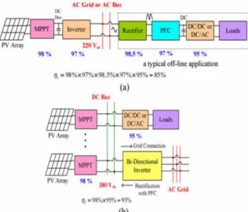
In an ac-bus system, the maximum power point tracker (MPPT) will draw maximum power from photovoltaic (PV) arrays and inject the power into ac bus or ac grid through an inverter. For a typical offline application, such as electronic ballast, personal computer, or variable speed appliance, it usually has a rectifier, a power factor corrector (PFC), and a dc/dc or dc/ac converter to supply the loads. However, this ac system leads to high power conversion loss. Thus, the concept of “dc grid” or “dc distribution” system has been presented recently, and the system configuration is illustrated in Fig. 1(b). It can be calculated that the power conversion efficiency in the ac-bus system is less than that in the dc-bus system about 8%. In addition, the dc-bus system can also save one rectifier and one PFC, saving component cost around 25%. Therefore, the dc distribution system is feasible in renewable energy applications.
The dc distribution system requires a dc-bus voltage control to balance the power flow among PV panels, dc loads, and ac grid. When the overall PV power is higher than the dc load power, the bidirectional inverter, as shown in Fig. 1(b), needs to sell power to ac grid, which is often defined as grid-connection mode. On the contrary, the
inverter will buy power from ac grid, which is a rectification, namely “rectification mode.” Moreover, since in a dc distribution system, the dc-bus voltage is sensitive to step load changes, the control of dc-bus voltage is more critical than that in a grid-connected inverter system. In the past studies, the voltage control based on gain scheduling was presented, which use a droop concept to design proper dc gain. Moreover, some attempts combing the gain-scheduling with fuzzy control were also discussed, which incorporate fuzzy control and adjust dc voltage reference to balance power flow.
Fig. 1 Conceptual configurations of (a) an ac-bus system and (b) a dc distribution system
This effect can help the proposed control approach to stabilize the dc-bus voltage regulation. Moreover, the approaches for achieving fast dc-bus voltage dynamics were focused on the systems without dc loads, while there is no control for the bidirectional inverter systems with fast dc load variation. In our previous research, a digital controlled 10-kVA 3φ bidirectional inverter with wide inductance variation has been designed and implemented. Based on its configuration, this paper presents two dc-bus voltage regulation approaches, one line-cycle regulation approach (OLCRA) and one-sixth line-cycle regulation approach (OSLCRA), which are based on a linear power management scheme. They are chosen by considering that the dc-bus capacitance should be large enough (typically>4000μF) to extend the hold-up time, and a short time interval does not vary the dc-bus voltage significantly even under high power change. Moreover, the OSLCRA is chosen for that the control laws for each region are changed every one-sixth line cycle, and the complexity of firmware programming can be reduced. The OLCRA is enacting for light load change while the OSLCRA is for heavy load change. The control laws of the two approaches require the information of dc-bus capacitance. It needs to determine the total capacitance on the dc bus. In a dc distribution system, dc loads or dc products having electrolytic capacitors are not desired to prevent inrush current.
The capacitors are installed in the inverter or in a separate box, and dc-bus capacitance estimation is only required at the start-up of the system operation. Several methods to estimate capacitance have been presented, where a dc-bus capacitance estimation method for ac/dc/ac pulse width modulation converter systems can determine the capacitance online with voltage injection. In this paper, an online capacitance estimation method with a capacitor pre-charging circuit at the system start-up is presented, which does not need extra inverter input current feedbacks. The proposed two control approaches can reduce the frequency of operation-mode change and current distortion significantly. In addition, they can improve the availability of the dc distribution system without increasing dc-bus capacitance.
II. DETERMINATION OF CAPACITOR SIZE AND CAPACITANCE ESTIMATION
The proposed system design is based on the power ratings of renewable sources, storage elements, dc load requirements, and the bidirectional inverter. The size of capacitors will affect the dc-bus voltage ripple and hold-up time. Thus, it needs to determine its size first, and then estimate the total capacitance online because of its tolerance.
A. Determination of Capacitor Size
In determining the capacitor size for the system, two major aspects are considered: dc-bus voltage ripple and energy-storage capability.
1) DC-Bus Voltage Ripple: By neglecting the ripple current of the three-phase inductors, instantaneous output power
Pac from the inverter is given by
WhereVRN,VSN, andVTN are the amplitudes of the phase voltages;IR,IS, and ITare their current amplitudes; ωlis the line angular frequency; and θ is the phase between ac currents and voltages. If the 3φpower source is unbalanced, there will exist voltage ripple every one-twelfth line period,
Tl/12, and it can be derived from the following equation:
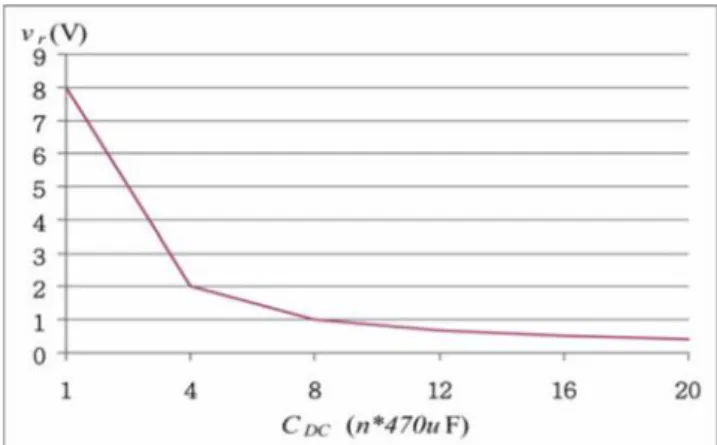
Where vDC MAX and vDC MIN are the peak and valley values of the dc-bus voltage ripple, respectively, andPavg is the average power of the inverter input power. Assuming the system is operated in the maximum power rating, 10kW, two of the phase voltages have the maximum and minimum unbalanced variations of 10%. A plot of dc-bus capacitance
CDC versus dc-bus voltage ripple is illustrated in Fig. 2. It can be seen that when the capacitance is higher than 8× 470
μF, the voltage ripple is lower than 1V. Therefore, we can select PV capacitorCpv = 12× 470μF, which is sufficient enough to filter out the ripple effect from the unbalanced grid voltages.
Fig. 2 Plot of dc-bus capacitanceCDC versus dc-bus voltage ripplevrunder unbalanced grid voltages
Moreover, there is another voltage ripple effect resulting from non-constant inductors. Assuming the three-phase inductors are identical but with wide inductance variation, the total energy variation will swing at six times line frequency, corresponding to the six-region transitions. The peak-to-peak voltage ripple can be then derived from the following equation:
Fig. 3 shows a plot ofCDC versus voltage ripplevr
significant and can be ignored. However, the capacitor must hold the dc-bus voltage during abrupt power changes, and it will be determined according to energy-storage capability.
Fig. 3 Plot of dc-bus capacitanceCDC versus dc-bus voltage ripplevrunder a maximum output power of 10 kW
2) Energy-Storage Capability: Fig. 4 shows a plot ofCDC versus dc-bus voltage variation ΔvDC under a maximum power change of 10kW and within one-sixth line cycle. For power supply availability, the voltage variation must be lower than 20V (400 –380V or 380–360 V) within one-sixth line cycle, and 12×470-μF capacitance can be selected to fit the appropriate range of dc-bus voltage variation, 10–15V. This set of capacitors was used in the experiment.
Fig. 4 Plot of dc-bus capacitanceCDC versus dc-bus voltage variation ΔvDC under a 10-kW abrupt change and within
one-sixth line cycle
B. Capacitance Estimation
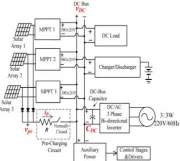
The proposed online capacitance estimation method uses the relationship between dc-bus voltage variation and capacitor current injection, and is based on the capacitor pre-charging circuit. The overall system configuration with a pre-charging circuit is shown in Fig. 5, where the circuit includes a resistorRand a relay (normally closed). When any of the three solar arrays generates power, it will charge the dc-bus capacitor through the resistor. The capacitanceCDC can be then determined as
Where ΔvDC is the dc-bus voltage variation during time interval ΔT, and iRis the current through resistor R. Since there is no feedback from resistor currentiR, it is determined as
Where Vpv is the solar array voltage. The proposed capacitance estimation is only working during the pre-charging time interval, because the dc distribution system has themerit that all of dc-bus capacitors are installed at the input terminal of the inverter or in a separate box, as shown in Fig. 5. An illustration of the proposed estimation method is shown in Fig. 6. During a sampling period ΔT, the estimation equation in (4) can be rewritten as
The inverter microcontrollers will feedback the voltages,
vDC andvpv, to determine the dc-bus capacitance from (6). Moreover, the inverter controller will estimate the capacitance automatically when the auxiliary power output is available and the CPU is working. At this moment, the CPU’s timer starts to count.
Fig. 5 Configuration of the proposed dc distribution system with a capacitor pre-charging circuit
Although the dc-bus voltage variation ΔvDC will change with different start-up times, it does not deteriorate in the estimating results. In the estimation tests, the sampling period ΔT was 10ms, resistor R = 200 Ω was selected, and four different dc-bus capacitances, 8× 470, 10
× 470, 12 × 470, and 16 × 470 μF, were, respectively, implemented. A comparison between the estimated and measured data for the different dc-bus capacitances is listed in Table I. The estimation errors are all within 1%, which does not penalize the accuracy of the dc-bus voltage regulation.
TABLE I
COMPARISON BETWEEN MEASURED AND ESTIMATED CAPACITANCES
C. DC-BUS VOLTAGE CONTROL
A diagram of the discussed three-phase bidirectional inverter is shown in Fig. 7. It can fit to both delta-connected and Yconnected ac grid. In the designed prototype, Renesas microchip RX62T is adopted for realizing the system controller, which has 1.65 MIPS and includes floating-point calculation and division. By considering wide inductance variation, the inverter can be operated stably, especially in high-current applications. Additionally, the system requires dc-bus voltage control schemes for balancing power flow. It includes linear power management scheme, one line-cycle regulation approach, and one-sixth line cycle regulation approach. A stability analysis is presented to support the proposed regulation approaches.
1. Linear Power Management Scheme
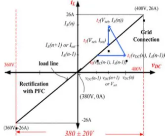
In a system design, the maximum PV power and the maximum dc load power will not exceed the inverter capability. In our developed system, both of the two maximum powers are 10kW. Fig. 8 shows an illustration of the proposed linear power management scheme for achieving a linear relationship between inductor current iL
and dc-bus voltage vDC. The operating range of the dc-bus voltage is 380±20V. When the inverter is operated in grid-connection mode (selling power), the operating range is from 380 to 400V, which ensures an enough voltage level to accommodate abrupt dc load increase. On the other hand, when the inverter is operated in rectification mode (buying power), a lower dc-bus voltage stands for a higher load power. Therefore, in rectification mode, the system does not have extra high enough dc load power to pull the dc-bus voltage below the lower bound. In short, in grid-connection mode, dramatic voltage drop is the major concern when loads are connected to the dc bus, while in rectification mode, sudden voltage jump up is another concern when loads are disconnected from the dc bus.
Fig. 7 Diagram of the proposed three-phase bidirectional inverter
Fig. 8 also shows the locus of the dc-bus voltage regulation sequence in grid-connection mode. At timet0, the inverter stays at operating point (vDC(n –1), IA(n –1)) on the load line, whereIAis the adjustable current command which is tuned every line cycle with the OLCRA. The operating point will move away from the load line to point (vDC(n), IA(n –1)) att1 when there exists power imbalance. Then, the controller will update current commandIA(n –1) withIA(n) at the beginning of thenth line cycle, which will regulate dc-bus voltage to a new set-point voltagevDC(n + 1) according to the linear power management scheme. When the inverter reaches operating point (vDC(n+1), IA(n)) att2 , the controller will change current command to IA(n + 1), maintaining dc-bus voltage vDC for a new power balance. The system will be operated in the new steady state after time t3. The proposed voltage regulation approaches are based on the linear power management scheme and presented in the following section.
Fig. 8 Illustration of a linear power management scheme for achieving a linear relationship between inductor currentiL
and dc-bus voltagevDC
2 One Line-Cycle Regulation Approach
instance, will increase fromvDC(n –1) tovDC(n). At time
tn,dc-bus capacitor current variation ΔiCcan be determined as
Fig. 9 Illustration of the OLCRA to dc-bus voltage regulation for the dc distribution system with power
imbalance
However, time tx1 is unpredictable, and an initial guess is made to tn−1 ; thus, new current commandIA(n) for time interval [tn , tn+1] can be determined based on previous currentIA(n –1) as
where Tl is a line period,KDA is a mapping ratio between dc input current and ac output current, which is equal to vDC/VAC (VAC is the RMS value of ac grid voltage, typically 220 V), and the initial current command
IA(0) is equal to zero at the system start-up. Once the system gets started, current command IA(n – 1) will be updated cycle by cycle. VoltagevDC(n+ 1) is the set-point voltage, which can be derived based on the relationship shown in Fig. 8, as follows:
In the above equations, IA(n) is always used for regulating dc-bus voltage to set-point voltage vDC(n + 1) according to the control diagrams shown in Figs. 8 and 9. The inverter controller will update current command IA(n) cycle by cycle, that is,IA(i) will be loaded toIA(I –1) after the new current command has been determined at the beginning of a line cycle. In Fig. 9, if another power imbalance occurs at tx2 (curve 2), the inverter will tune current command IA continuously to follow curve 2 and reach another set-point.
3. One-Sixth Line-Cycle Regulation Approach
If dc loads change abruptly, the OLCRA cannot regulate dc bus voltage immediately, and it needs a fast dynamic current control to balance the power flow. In a three-phase inverter system, the fast regulation interval is selected to be one-sixth line-cycle according to each zero-crossing point of the three phase line currents. Since the voltage ripple on the dc-bus is insignificant in a three-phase
inverter system with even 10% unbalanced three-phase voltage sources, the voltage ripple can be ignored in the control law derivation.
Fig. 10 illustrates the current tuning process of the proposed OSLCRA. With the OSLCRA, the inverter will update current commandIAat the beginning of each one-sixth line-cycle to drive dc-bus voltage to set-point voltagevDC(n+ 1) at timetn+1. Thus, according to a dc-bus voltage variation, the current command control law can be derived as follows:
Voltage variation Δvi includes two portions: one is the variation ΔvDC(T ) between two consecutive one-sixth cycles, and the other is the average difference ΔvDC(A) betweenvDC(n+1) and the current operating point:
And
Fig. 10 Illustration of the OSLCRA to dc-bus voltage regulation for the system under power imbalance
the dc-bus voltage will not be regulated to a correct voltage value until next one-sixth line cycle, tn+ 2Tl/6. If another power imbalance occurs at ty 2 (curve 3), the same regulation process will be conducted again. That is, the inverter will use a correct current command IA(n + 3/6) to regulate the dc-bus voltage to a set-point voltage. Furthermore, current command IA(n) must be modified for determining commandIA(n + 1) at the beginning of a new cycle due to the one-sixth line-cycle command change, and it is just equal to the average value of all current commands within the time interval of [tn,tn+1]. The determination of current commandIA(n) can be expressed as
III. SIMULATION RESULTS
Fig 11 simulation diagram of proposed system
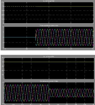
Fig. 11.Measured waveforms of the three-phase inductor currents and dc-bus voltagevDC for dc load variation (a) from no load to 800Wand (b) from 800W to 2 kW in
rectification mode with BSS
Fig. 12 Measured waveforms of the three-phase inductor currents and dc-bus voltagevDC for dc load variation (a)
from no load to 3kW and (b) from 3 to 1.5 kW in rectification mode with BSS
Fig 13 measured waveforms of BSS
CONCLUSION
REFERENCES
[1] T.-F. Wu, K.-H. Sun, C.-L. Kuo, and C.-H. Chang, “Predictive current controlled 5-kW single-phase bidirectional inverter with wide inductance variation for dc-microgrid applications,”IEEE Trans. Power Electron., vol. 25, no. 12, pp. 3076–3084, Dec. 2010.
[2] L. Xu and D. Chen, “Control and design of a DC microgrid with variable generation and energy storage,”
IEEE Trans. Power Del., vol. 26, no. 4, pp. 2513–2522, Oct. 2011.
[3] Z.-H. Ye, D. Boroyevich, K. Xing, and F.-C. Lee, “Design of parallel sources in DC distributed power systems by using gain-scheduling technique,” inProc. IEEE Power Electron. Spec. Conf., Aug. 1999, pp. 161–165.
[4] Y. Ito, Y. Zhongqing, and H. Akagi, “DC microgrid based distribution power generation system,” inProc. IEEE Int. Power Electron. Motion Control Conf., Aug. 2004, pp. 1740–1745.
[5] J. M. Guerrero, J. C. Vasquez, J. Matas, L. G. D. Vicuna, and M. Castilla, “Hierarchical control of droop-controlled AC and DC microgrid—A general approach toward standardization,”IEEE Trans. Ind. Electron., vol. 58, no. 1, pp. 158–172, Jan. 2011.
[6] H. Kakigano, A. Nishino, and T. Ise, “Distributed voltage control for DC microgrid with fuzzy control and gain-scheduling control,” in Proc. IEEE Int. Conf. Power Electron., 2011, pp. 256–263.
[7] H.Kakigano,Y. Miura, and T. Ise, “Low-voltage bipolar-type dc microgrid for super high quality distribution,”IEEE Trans. Power Electron., vol. 25, no. 12, pp. 3066–3075, Dec. 2010.
[8] J.-S. Park, J.-K. Choi, B.-G. Gu, I.-S. Jung, E.-C. Lee, and K.-S. Ahn, “Robust DC-Link voltage control scheme for photovoltaic power generation system PCS,” inProc. IEEE Int. Telecommun. Energy Conf., Oct. 2009, pp. 1–4.
[9] D. Salomonsson, L. Soder, and A. Sannino, “An adaptive control system for a DC microgrid for data centers,”IEEE Trans. Ind. Appl., vol. 44, no. 6, pp. 1910– 1917, Nov./Dec. 2008.
[10] J.-S. Park, J.-K. Choi, B.-G. Gu, I.-S. Jung, E.-C. Lee, and K.-S. Ahn, “A hybrid renewable DC microgrid voltage control,” inProc. IEEE Int. Power Electron. Motion Control Conf., May 2009, pp. 725–729.
[11] Z. Li, T. Wu, X. Yan, K. Sun, and J. M. Gurrero, “Power control of DC microgrid using DC bus signaling,” in
Proc. IEEE Appl. Power Electron. Conf., Mar. 2011, pp. 1926–1932.
[12] A. Engler, “Applicability of droops in low voltage grids,” Int. J. Distrib. Energy Res., vol. 1, no. 1, pp. 1–5, Jan. 2005.
[13] J. A. Restrepo, J. M. Aller, A. Bueno, J. C. Viola, A. Berzoy, R. Harley, and T. G. Habetler, “Direct power control of a dual converter operating as a synchronous rectifier,”IEEE Trans. Power Electron., vol. 26, no. 5, pp. 1410–1417, May 2011.
[14] M. G. Molina and P. E. Mercado, “Power flow stabilization and control of microgrid with wind generation by superconducting magnetic energy storage,” IEEE Trans. Power Electron., vol. 26, no. 3, pp. 910–922, Mar. 2011. [15] Y. C. Chang and C. M. Liaw, “Establishment of a switched-reluctance generator-based common DC microgrid
system,” IEEE Trans. Power Electron., vol. 26, no. 9, pp. 2512–2527, Sep. 2011.
[16] N. Hur, J. Jung, and K. Nam, “A fast dynamic DC-link power-balance scheme for a PWM converter-inverter system,”IEEE Trans. Ind. Electron., vol. 48, no. 4, pp. 794– 1803, Aug. 2001.
[17] J. Yao, H. Li, Y. Liao, and Z. Chen, “An improved control strategy of limiting the DC-link voltage fluctuation for a doubly fed induction wind generator,” IEEE Trans. Power Electron., vol. 23, no. 3, pp. 1205–1213, May 2008. [18] T.-F. Wu, L.-C. Lin, C.-H. Chang, Y.-L. Lin, and Y.-C. Chang, “Current improvement for a3 bi-directional inverter with wide inductance variation,” inProc. IEEE ECCE Asia, May/Jun. 2011, pp. 1777–1784.
[19] E. Aeloiza, J.-H. Kim, P. Enjeti, and P. Ruminot, “A real time method to estimate electrolytic capacitor condition in PWM adjustable speed drives and uninterruptible power supplies,” in Proc. IEEE Power Electron. Spec. Conf., Jun. 2005, pp. 2867–2872.
[20] A.-G. Abo-Khalil and D.-C. Lee, “DC-link capacitance estimation in AC/DC/AC PWM converters using voltage injection,”IEEE Trans. Ind. Appl., vol. 44, no. 5, pp. 1631– 1637, Sep. 2008.
[21] A. J. Roscoe, S. J. Finney, and G. M. Burt, “Tradeoffs between AC power quality and DC bus ripple for Phase 3-wire inverter-connected devices within microgrids,” IEEE Trans. Power Electron., vol. 26, no. 3, pp. 674– 688, Mar. 2011.
[22] G. Petrone, G. Spagnuolo, and M. Vitelli, “Optimization of perturb and observe maximum power point tracking method,”IEEE Trans. Power Electron., vol. 20, no. 4, pp. 963–973, Jul. 2005.
[23] A. Khaligh, C. H. Rivetta, and G. A. Williamson, “Constant power loads and negative impedance instability in automotive systems: Definition, modeling, stability, and control of power electronic converters and motor drives,”
IEEE Trans. Veh. Technol., vol. 55, no. 4, pp. 1112–1125, Jul. 2006.