Design and Performance Analysis of slotted E-Shape Micro-strip Patch
Antenna for Wireless Applications
V.Ramesh, PG Scholor
Vasireddy Venkatadri institute of Technology, Guntur, A.P, India
Abstract: This paper introduces the design and simulation
of E-shape microstrip patch antenna displaying wideband operating frequencies for different wireless applications. This antenna will give the wide data transmission which is required in different applications like wireless detecting, biomedical application, versatile radio satellite, wireless correspondence and so on. The coaxial encourage or test nourish system is utilized as a part of the test. The execution of the planned antenna was broke down as far as data transfer capacity, pick up, return misfortune, VSWR, and radiation design. The outline is upgraded to meet the most ideal result. The proposed antenna is planned via air substrate which has a dielectric consistent of 1.0006. The outcomes demonstrate the wideband antenna can work from 2.2 to 8.2 GHz frequency band with ideal frequency at 4.4 GHz. Miniaturized scale strip antennas are generally utilized as a part of numerous applications because of their position of safety, minimal effort and simplicity of manufacture. In a few applications it is craved to have a double band or multiband qualities. This paper shows the outline of E-shape small scale strip patch antenna with wideband operating frequency for wireless application. The shape will give the wide transfer speed which is required in different application like wireless detecting, biomedical application, portable radio, satellite correspondence and so forth.
Keywords: E-shaped Antenna, Wireless Communication,
high gain, microstrip patch antenna, probe feed
1. INTRODUCTION
Microstrip patch antenna is critical for wireless correspondence as far back as it was first appeared in the year of 1886 by Heinrich Hertz and its reasonable apparatus by Gugliemo Marconi in 1901. Microstrip patch antenna have been acclaimed for its advantages like light weight, low manufacture cost, mechanically extreme when mounted on firm surfaces and capacity
of double and triple frequency exhibitions. By the by, restricted data transfer capacity is one of the primary downsides for this sort of antenna. Different
is a primary working in wireless correspondence, Based on this antenna execution effortlessly to break down viability of the wireless correspondence around the globe. Antenna is a conduit which conveying the current.it is utilized to change over the electrical vitality to electromagnetic waves and it can transmit over the more extended separation. The fundamental effect of the antenna in wireless correspondence is utilized to transmit and get the data by means of the air. The transmitting antenna have distinctive extents like Low frequency range, Mid frequency range, High frequency range, Ultra high frequency, and microwave frequency range. In the transmitter side a radio transmitter supplies the electric present as electromagnetic waves. Antenna are key segments for all gear that is utilized for radio telecom, TV, two-way radio, correspondence collectors, radar, mobile phones, and satellite interchanges and also wireless amplifiers, Bluetooth empowered gadgets, wireless PC systems, and RFID.The antenna outline can have distinctive parameters like increase, VSWR, Directivity, Radiated power, productivity, Return Loss, Impedance.
2. METHODOLOGY
A. Outline of E-Shaped Slot
General Design of Patch Antennas
In this area there is given a configuration the utilization of –Microwave HFSS reenactment programming.
As a matter of first importance we need to pick a dielectric consistent and substrate stature to outline a radio wire as these are the rudiments for the configuration a reception apparatus. They were picked by configuration recurrence (8.83GHz). There was picked substrate material is air with dielectric steady.
1. Substrate Height =3.2 mm
2. Dielectric Constant=1.0006
B. Outlining parameters:
* Calculation of the Width ( W)
* Calculation of Effective dielectric steady
(ɛ )
* Calculation of the Effective length ( )
* Calculation of the length augmentation (∆L) Calculation of real length of patch (L).
C. Planning Equations
The underneath conditions are utilized to discover the length and width of patch.The width of the patch is discovered by
(2.1)
2.2)
(2.3)
(2.4)
(2.5)
Where the measurements of the patch along its length have been stretched out on every end by a separation ΔL, which is an element of the successful dielectric steady εreff and the width to-tallness proportion (W/h), and the standardized expansion of the length, is The augmentation length has been adjusted into the structure and the genuine length of patch( L ) can be resolved.
3. ANTENNA CONFIGURATION
the figure 1, the aggregate perspective of a basic E-space patch reception apparatus is planned by utilizing HFSS programming. In this we utilize a coaxial encouraging with gap sort. The opening piece is at the tallness of 3.2mm starting from the earliest stage. The fundamental reason for this is to enhance the coordinating between the nourishing and the transmitting component.
Figure 3.1: Cut plane view of antenna
E. Recreation SetupThe radio wire's resounding properties were anticipated and improved utilizing CST 2014. The outline system starts with deciding the length, width and the kind of dielectric substance for the given working recurrence. At that point utilizing the estimations acquired above reenactment has been setup for the fundamental rectangular miniaturized scale strip reception apparatus and the parameters are advanced for the best impedance coordinating. Besides two parallel spaces are fused and advanced with the end goal that it nearly looks like E shape; this expands the addition of the recieving wire. After that two more parallel openings and one opposite space are fused and enhanced with the end goal that it nearly looks like U shape. At that point dielectric substrate of dielectric consistent of 1.0006 acquaints with lessening the extent of the recieving wire and to further improve the data transfer capacity. Finally the test nourishing is presented for achieving a required transfer speed, resounding recurrence and addition esteem.
F. Geometry of Antenna
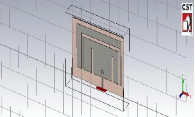
The geometry of the outlined recieving wire is appeared in the Figure 3.2.The radio wire is made of a solitary patch on main, one layers of dielectric (air) and a vertical test associated from ground to the upper patch. The primary E molded patch has Wa x La measurement while the external patch has Wb x Lb measurement. The reception apparatus is
nourished by a SMA connector situated at the inside arm. The focal point of test is situated at (Wc/2,Lf).
Figure 3.2: Design geometry of the E-shape micro strip patch.
Parallel openings in this outline are in charge of the excitation of next full mode i.e. primary parallel opening energize second full recurrence while external space energize third thunderous recurrence. Openings length (LsA and LsB), space width (S), principle opening width (WsB) and focus arm (Wc) controls the recurrence of the following resounding mode. Figure 3 demonstrates the cut plane perspective of the reception apparatus. The patch and ground are isolated by shut cell low misfortune demeanor of thickness 3.2 mm. Dielectric consistent for this froth is 1.0006, and it advantages to get more extensive data transmission and higher increase. Air hole was utilized as substrate and unbounded ground was expected. This paper outline a limited arrangement of ground measurement which is characterized by Wg x Lg. SMA connector outline is as indicated by determination in utilizing Teflon of dielectric consistent = 2.08
4. PROPOSED ANTENNA DESIGN
The side perspective of the proposed radio wire structure has been appeared in Fig. 3.3. The expansive banding strategy of stacked layers is utilized to enhance the transmission capacity. An air box of tallness 1mm is embedded amongst substrate and the ground. The Roger RO4350 of 1.6mm thickness having relative permittivity of 3.66 and dielectric misfortune digression of 0.004 has been utilized as substrate. The substrate and ground size has been considered as 33.2mm x 27.2mm. The radio wire is test feeded. The bolstering technique is anything but difficult to manufacture yet hard to display precisely and have low spurious radiation and tight data transfer capacity of impedance coordinating [1]. The area of the food component regarding the patch likewise assumes a part in the radio wire execution. The patch geometry has been appeared in Fig. 3.2. The comparing measurements are recorded in Table I. The two rectangular spaces, one in every upper and lower edge of the fundamental E-formed patch have been presented and two rectangular opening strips symmetrical and parallel to the y-hub have been cut from the primary patch. The two square openings are inserted at the two corners of the left edge of the patch. Every one of these openings have been incorporated into the configuration to accomplish the fancied radio wire execution. The food point is situated at ( 1mm, -7mm).
Fig 4. Perspective view of the proposed antenna
5. RESULTS AND DISCUSSION
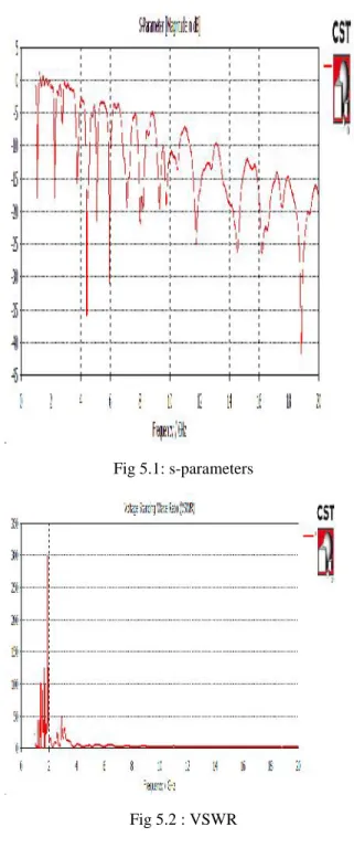
The proposed system with a return loss of multi band frequencies at 2.2Ghz ,3.7 , 4.4 ,5Ghz,6Ghz,7Ghz and 8Ghz with a values of -10.18,-14.48,-32.85, 20.98,-18.84,-19.23 and -21.79 db used in the applications of wlans, wimax, laptops, Ethernet and radar applications.the proposed antenna with a vswr less than or equal to 2. The simulation results of
proposed antenna with magnetic field ,surface current distrubtion and far field patterns shown in below figures 5.3,534 and 5.5
Fig 5.1: s-parameters
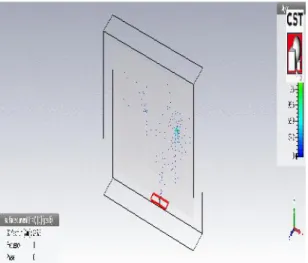
Fig 5.3 : Magnetic field representation of proposed antenna
Fig 5.4 : Surface current distribution of proposed antenna
Fig 5.5 : Fairfield results of proposed antenna
6. CONCLUSION
In this paper, an E-shaped wideband microstrip patchantenna using C-Foam PF-2 has been designed, simulated,optimized and analyzed using CST 2014 software. Aparametric study is presented with the results showing that theantenna can be operated at 2.2 GHz up to 8.2 GHzfrequency band. This result is an improvement when comparedto the original specification which saw the bandwidth is expanded from 4.99 GHz to 5.72 GHz. Other parameters such as gain, S11and VSWR also have been improved.
REFERENCES
[1] Balanis, C.A., 2005. Antenna Theory: Analysis and Design. 3rd Edn., John Wiley, Hoboken, ISBN: 047166782X, pp: 1117.
[2] Yoharaaj, D. Azmir and Raja Syamsul, “A New Approach for Bandwidth Enhancement Technique in Microstrip Antenna for Wireless Applications,” RF and Microwave Conference, 2006. RFM 2006. International, 2006, Page(s): 205–209.
[3] Rafi, G. and L. Shafai, “Broadband microstrip patch antenna with Vslot,” IEE Proc. Microw. Antenna Propag., Vol. 151, No. 5, 435–440, October 2004.
[4] Islam, M. T., M. N. Shakib, and N. Misran, "Multi-slotted microstrip patch antenna for wireless communication," Progress in Electromagnetics Research Letters, Vol. 10, 11-18, 2009.
[5] Lee, K. F., K. M. Luk, K. F. Tong, S. M. Shum, T. Huynh, and R. Q., “Experimental and simulation studies of the coaxially fed U-slot," Proc. Inst. Elec. Eng., pt. H, Vol. 144, 354-358, Oct. 1997.
[6] Lee, K. F., et al., “Experimental and simulation studies of the coaxially fed U-slots rectangular patch antenna,” IEE Proc. Microw. Antenna Propag., Vol. 144, No. 5, 354–358, October 1997.
Asia-Pacific Conference on Communications , Japan, October 2008.
[8] H. F. AbuTarboush and H. S. Al-Raweshidy, “A Connected E-Shape and U-Shape Dual-Band Patch Antenna for Different Wireless Applications”, the Second International EURASIP Workshop on RFID Technology, July, 2008.
[9] Weigand, S., G. H. Huff, K. H. Pan, and J. T. Bernhard, “Analysis and design of broad-band single-layer rectangular U slot microstrip patch antennas,” IEEE Transactions on Antenna and Propagation, Vol. 51, No. 3, 457–468, March 2003.