AXNET
Access Controller
Browser Interface
& PC Utility Software
Installation and
User’s Guide
For Version 2
with Windows 7 Support
Compatible with
Access Controllers:
AM3Plus
AE1000Plus
AE2000Plus
PRINTER’S INSTRUCTIONS:
1 Introduction . . . 1
2 System Requirements . . . 1
3 Summary of AXNET Features . . . 2
4 Access Controller Setup for AXNET Mode of Operation . . . 3
5 Installing the AXNET PC Utility Software . . . 4
Utility Installation . . . 4
If Timestamps Did Not Enable . . . 5
6 Confi guring a Windows 7 Direct Serial Connection for AXNET . . . 6
Creating the Cable Port . . . 6
Creating the Dial-up Connection . . . 7
Confi guring the Connection Port . . . 8
Testing the Direct Cable Connection . . . 9
7 Confi guring a Windows 7 Modem Connection for AXNET . . . 10
Setting Up the Modem Connection . . . 10
Testing the Modem Connection . . . 11
8 Confi guring a Windows XP Direct Serial Connection for AXNET . . . 12
Creating the Cable Connection . . . 12
Assigning the Cable Port . . . 13
Creating a Cable Port . . . 13
Confi guring the Connection Port . . . 15
Testing the Direct Cable Connection . . . 16
9 Confi guring a Windows 2000 Direct Serial Connection for AXNET . 17 Creating the Cable Connection . . . 17
Creating a Cable Port . . . 18
Confi guring the Connection Port . . . 20
Testing the Direct Cable Connection . . . 21
10 Confi guring a Windows XP Modem Connection for AXNET . . . 22
Setting Up the Modem Connection . . . 22
Testing the Modem Connection . . . 24
11 Adding a Windows XP Shortcut Icon for the Connection . . . 24
12 Confi guring a Windows 2000 Modem Connection for AXNET . . . 25
Setting Up the Modem Connection . . . 25
Testing the Modem Connection . . . 27
13 Adding a Windows 2000 Shortcut Icon for the Connection . . . 28
14 Initiating an AXNET Browser Interface Session . . . 28
15 Network Installation Basics . . . 29
16 Networked Installation Maintenance . . . 30
17 Network Troubleshooting . . . 30
18 AXNET PC Utility Software Basics . . . 31
18.1 Launching The AXNET PC Utility Software . . . 31
18.2 Tools . . . 31
18.2.1 Backup/Restore . . . 31
18.2.2 Firmware Update . . . 33
18.2.3 Preferences . . . 33
18.2.4 Download Eventlog . . . 34
18.3 Eventlog Reports . . . 34
19 AXNET Browser Interface Navigation Tree . . . 35
20 AXNET Browser Interface Screen Shots and Descriptions . . . 36
20.1 Main Screen . . . 36
20.2 Cardholders> Cardholders Screen . . . 36
20.3 Cardholders> Add Cardholders Screen . . . 36
20.3.1 Directory Codes . . . 37
20.3.2 Entry Codes . . . 37
20.3.3 Block Transmitters . . . 38
20.3.4 Single Transmitters . . . 38
20.3.5 Block Cards . . . 38
20.3.6 Single Cards . . . 38
20.4 Cardholders> Cardholder Sets Screen . . . 39
20.5 Cardholders> Batch Entry Screen . . . 40
20.6 Eventlog Screen . . . 41
20.7 Backup/Download Screen . . . 41
20.7.1 Backup . . . 41
20.7.2 Download Eventlog Records . . . 41
20.8 Credentials> Block Cards Screen . . . 42
20.9 Credentials> Block Transmitters Screen . . . 43
20.10 Global Settings> Validation Groups Screen . . . 44
20.11 Global Settings> Time Zones Screen . . . 44
20.12 Global Settings> Door Schedules Screen . . . 44
20.13 Global Settings> Button Schedule . . . 44
20.14 Global Settings> Operators Screen . . . 45
20.15 Global Settings> Custom Labels . . . 45
20.16 Global Settings> Downlight Time . . . 45
20.17 Global Settings> Expiring Holidays . . . 45
20.18 Global Settings> Non-Expiring Holidays . . . 45
20.19 Global Settings> Telephone Directory . . . 46
20.20 Global Settings> Anti-Passback . . . 47
20.21 Global Settings> Display Messages . . . 47
20.22 Global Settings> Auto Time Sync . . . 47
20.23 Global Settings> Networking . . . 47
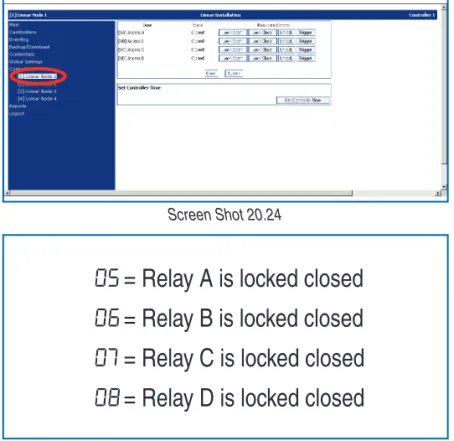
20.24 Controllers> My Controller (n) . . . 48
20.25 Controllers> My Controller (n)> Setup . . . 48
20.26 Controllers> My Controller (n)> Relays . . . 49
20.27 Controllers> My Controller (n)> Modem . . . 50
20.28 Controllers> My Controller (n)> Obstacle Transmitter . . . 50
20.29 Controllers> My Controller (n)> Remote Devices. . . 51
20.30 Reports> System Report . . . 52
20.31 Reports> Network Report . . . 52
20.31.1 Restart Submit Queue . . . 52
20.31.2 Database Resync . . . 52
20.32 Reports> Cardholders . . . 53
20.33 Reports> Cards . . . 53
20.34 Reports> Transmitters . . . 54
20.35 Reports> Entry Codes . . . 54
20.36 Reports> Directory Codes . . . 54
20.37 Reports> Confi guration . . . 55
20.38 Logout> Logout and Hangup . . . 55
20.39 Logout> Change Operator . . . 55
21 Appendix A - Defi nition of Front Panel Confi guration Modes . . . 56
22 Appendix B - Network Confi gurations . . . 57
23 Appendix C - Timestamp Batch Files . . . 58
Enabling Timestamps . . . 58
Viewing Timestamps . . . 58
1 Introduction
These instructions support Linear’s AXNET Access Controller Browser Interface & PC Utility Software.
This manual contains instructions for confi guring the access controllers for AXNET mode of operation, confi guring the host PC for AXNET browser access, and installation instructions for the AXNET PC Utility Software.
General operating procedures for new features provided by AXNET are also covered in this manual.
2 System
Requirements
This version of AXNET is designed to run with recent versions of Microsoft Windows and Internet Explorer.
AXNET has been tested on:
• Windows 7 Professional (32-bit and 64-bit versions) • Windows 7 Home Premium (32-bit and 64-bit versions)
• Windows XP Home
• Windows XP Professional
• Internet Explorer 6 through 9
AXNET requires a minimum of Microsoft Internet Explorer V5.5 to operate with Microsoft .NET version 1.1 and Java Runtime.
Compatibility with earlier versions of Windows and Internet Explorer is not guaranteed.
Minimum Hardware Requirements
• Intel / AMD 32-bit processor, minimum 300 MHz clock
• 128 MB RAM
• 300 MB free disk space
• 800 x 600 SVGA video minimum
• CD-ROM drive for software installation
• 9600 baud modem or greater; 33600 baud modem
recommended for optimum performance • Free RS-232 serial port if direct
serial connection is desired
Additional Software Requirements
• Software installation will require
Administrator level access.
• The Windows 7 operating system will ask for approval to modify the systems fi les. It is OK to allow access during the PC downloader application installation. • Microsoft .NET framework version 3.5 or higher
For further details, go to:
AXNET provides the capability to manage access controllers from any PC that has a modem or a direct serial connection to the master controller. The tenant database resides within the controllers, eliminating the need for the PC to host the database. Controllers running AXNET can be managed by fi rst completing a dial-up Internet connection to the master controller, and then launching an Internet browser.
AXNET-based installations can be confi gured for a variety of network confi gurations, and once changes have been made on the master controller, the master controller will automatically propagate changes to the other controllers via the RS-485 connection or by automatically dialing remote controllers through the modem.
The following are the salient features of AXNET:
Maximum number of controllers 4
Maximum number of host connection points (modem or direct) 4 Maximum number of PBUS peripherals (four per node) 16
Maximum number of doors (relays) 16
Maximum number of cardholders (four Validation Groups per
cardholder) 2000
Maximum number of card credentials 1600/block
2000 individual Maximum number of card blocks (includes facility code) 24
Maximum number of transmitter credentials 1600/block 2000 individual Maximum number of transmitter blocks (includes facility code) 24
Maximum number of key codes (fi xed length) 2000 Maximum number of directory codes (fi xed number - fi xed length) 2000
Maximum number of split directories 4
Maximum number of time zones (two periods per zone) 8
Maximum number of door schedules 8
Maximum number of validation groups 8
Maximum number of expiring holidays 10
Maximum number of non-expiring holidays 10 Maximum number of event log entries (per node) 2500 Maximum number of obstacle transmitters (per node) 2
Maximum number of operators 4
Individually enrolled cards 2000
Individually enrolled transmitters 2000
Supports expiring credentials Yes
Anti-passback (node basis only - lost on resets) Timed
Keypad “Strikes and Out” Yes
Relay modes supported (control, shunt, alarm, obstacle) Yes
Door ajar timing (global only) Yes
Door auto open/close (two Time Zones per relay) Yes Supported Wiegand formats (Wiegand 26, 30, 31) Yes Operator security levels (Operator, Supervisor, Administrator) Future Option
Button schedule (global only) Yes
4 Access Controller Setup for AXNET Mode of Operation
4.1
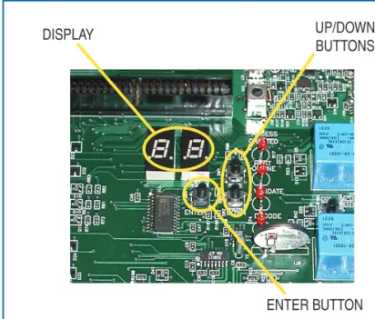
By default, the access controllers will be confi gured forAccessBase mode of operation. This can be verifi ed by examining the two-digit LED display on the front panel of the AM3Plus or the PCB assembly on the AE1000Plus and AE2000Plus. The display will sequence as follows on power-up.
A B
⁄
2
.
9
⁄
' 1
4.2
To switch to AXNET mode of operation, press the UP and DOWN buttons simultaneously for about 1 second, until a beep is heard. The following will be displayed:0
.
1
.
4.3
Press the UP button to cycle through the display untilA
.
n
. is displayed.The following shows the display sequence until
A
.
n
. is displayed.0.1
.
¼0
.
2
.
¼0
.
3
.
¼0
.
4
. ¼0
.
5
. ¼0
.
6
.
¼0
.
7
. ¼0
.
8
. ¼A
.
n
.Press the ENTER button to select the AXNET mode of operation.
4.4
A series of digits will fl ash andCL
will fl ash rapidly for a few seconds indicating that the AXNET database is being initialized. The display will fi nally sequence as follows, indicating AXNET mode of operation:An
¼1
.
4
¼'1
DISPLAY UP/DOWN
BUTTONS
ENTER BUTTON
Figure 1 - AE1000Plus/AE2000Plus Display and Buttons
Figure 2 - AM3Plus Display and Buttons
DISPLAY UP/DOWN
BUTTONS
Utility Installation
The following instructions are for installing the AXNET PC Utility Software.
NOTE: Before proceeding, run Windows Update to verify that the latest version system updates are installed.
5.1
Upon insertion of the Installation CD, the installation program willautomatically run.
If the installation program does not automatically run, open the CD or navigate to the fi le using Windows Explorer, and then double-click on cdSetupAXNET.bat.
The software can also be downloaded from Linear’s Web site. Run the AXNETInstall.exe executable to extract and install the program.
5.2
A black command window will pop-up and remain on the screen until the end of the installation. The batch fi le that executes in the window will enable timestamps when it runs.NOTE: This command window will wait for the installation to complete before executing.
5.3
The End User License Agreement for Microsoft .NET framework (if not already installed) and Crystal Reports Basic Visual Studio will display. Click “Accept”. The programs will start to install.5.4
If using Windows 7, it will ask if it’s OK to for the Windows installer to make changes to the computer. Click “Yes”.NOTE: For security, Windows 7 will ask this question at various times during the installation. You must click “Yes” to proceed each time the question is asked.
5.6
The programs will continue to install and fi nish.5.7
The AXNET setup wizard will start. Click on the “Next” button to continue.5.8
Select if the AXNET program can be access by everyone on the computer, or just yourself. Click on the “Next” button to accept the default installation path and continue, or enter a new path where AXNET is to be installed, then click on the “Next” button to continue.Screen Shot 5.2
Screen Shot 5.3
Screen Shot 5.4
Screen Shot 5.7
Installing the AXNET PC Utility Software (Continued)
5.9
Confi rm installation by clicking on the “Next” button.5.10
The installation progress bar will be displayed.5.11
If using Windows 7, it will ask if it’s OK to for the AXNET installation program to make changes to the computer. Click “Yes”. AXNET will display that the installation was successfully installed. Click on the “Close” button to fi nish the installation.5.12
The command window batch fi le will run when the Axnet installation is complete. If using Windows 7, it will ask if it’s OK to for the prepareAxnet.exe installation program to make changes to the computer. THIS WINDOW MAY BE HIDDEN AND WINDOWS WILL DISPLAY THE UAC SHIELD ICON ON THE TASKBAR (see Screen Shot 5.13), Click the UAC shield icon to display the UAC window, then click “Yes”.5.13
After timestamps are enabled successfully, Screen Shot 5.13 will be displayed. Click any key to close the command window.If Timestamps Did Not Enable
Timestamps pace the data transmission for TCP communications with the Linear access control panel. Timestamps must be enabled for the AXNET software to function properly.
5.14
Timestamps are normally enabled during installation. If for some reason the system did not run the batch fi le (usually due to permissions or Axnet installation failure), click any key to close the command window and refer to Appendix C for details on manually enabling timestamps.Screen Shot 5.9
Screen Shot 5.13 Screen Shot 5.12
Click Shield Icon
Creating the Cable Port
6.1
To set up a direct cable connection between a PC and an AXNET-enabled access controller, a Windows COM port connection must be established.6.2
Click the Windows “Start” button. In the “Search Programs and Files” area, enter “phone”. Click “Phone and Modem”.6.3
Under “Phone and Modem” select the “Modems” tab. Click“Add...”.
6.4
Check the “Don’t detect my modem...” box, then click “Next”.6.5
Wait for the list of devices to display. Under “Models”, select “Communications cable between two computers”, click “Next”.6.6
Select a port number for the cable, click “Next”.6.7
Wait while Windows installs the “modem” (it’s really just a COM port setup for a cable). When it indicates success, click “Finish”.Screen Shot 6.3 Screen Shot 6.2
Screen Shot 6.6 Screen Shot 6.4
Confi guring a Windows 7 Direct Serial Connection for AXNET (Continued)
6.8
Repeat Steps 6.3 to 6.7 and select the same COM portfor the cable. This will create a second communications cable connection. AXNET WILL ONLY USE ONE OF THESE CONNECTIONS. The second connection is required for Windows to allow custom setup of the port (Microsoft has indicated that future Windows versions may not support dial-up networking over a direct serial connection).
6.9
Click “OK” to close the “Phone and Modem” dialog box.Creating the Dial-up Connection
6.10
Click the Windows “Start” button. In the “Search Programs and Files” area, enter “dial”. Click “Set up a dial-up connection”.6.11
Windows will ask “Which modem do you want to use?”. Click “Communications cable between two computers #2”.6.12
Enter the ISP information:• For the “Dial-up phone number” enter “1” (not used, but required by Windows).
• For the “User name” enter “Linear” (must be a capital “L”). • For the “Password” enter “123456” (check
“Remember this password” if desired). • For the “Connection name” enter
“AXNET Direct Connect”.
• Click the checkbox if you want to allow AXNET access to other people who log onto this computer.
6.13
Click “Connect”, then when Windows tries to dial, click “Skip” and wait to continue.Screen Shot 6.10 Screen Shot 6.8
Screen Shot 6.11
Confi guring the Connection Port
6.15
Click the Windows “Start” button. In the “Search Programs and Files” area, enter “net con”. Click “Connect to a network”. (You can also just click on the network icon on the taskbar to see the connections).6.16
Right-click on the “AXNET Direct Connect” connection and click “Properties”. (Your system may display additional connections.)6.17
On the “General” tab, click “Confi gure...”.6.18
Set the “maximum speed (bps):” to 38400. Be sure all the “Hardware features” check boxes are not checked. Click “OK”, then click “OK” again.Screen Shot 6.16 Screen Shot 6.15
Screen Shot 6.17
Confi guring a Windows 7 Direct Serial Connection for AXNET (Continued)
Testing the Direct Cable Connection
6.19
Click the Network icon on the taskbar to display the network connections. (Note: The network icon will vary depending on your current connection).6.20
Click “AXNET Direct Connect”, then “Connect”.6.21
The connection password entry screen will display: • For the “User name” enter “Linear” (mustbe a capital “L”) if not already fi lled in.
• For the “Password” enter “123456” if not already fi lled-in. • For the “Dial-up phone number” enter “1”
(not used, but required by Windows). • Click “Dial”.
6.22
Windows will begin the connection sequence. The AXNET panel will display status windows as the connection is made. (These may go by real fast depending on the speed of the PC).6.23
Click the network icon on the taskbar to view the current connection status. “AXNET Direct Connection” should show “Connected”.Screen Shot 6.20 Screen Shot 6.19
Screen Shot 6.21
Setting Up the Modem Connection
7.1
Follow the modem manufacturer’s instructions and install aWindows 7 compatible modem on the PC.
7.2
To verify that the modem is installed and working properly, click the Windows “Start” button. In the “Search Programs and Files” area, enter “dev”. Click “Device Manager”. Click the arrow by “Modems” to expand the tree and view the installed modem, its name will be displayed on the list. It the modem is working correctly, no special icons will appear. If there are special icons displayed, correct any modem issues before proceeding. Close Device Manager.7.3
Click the Windows “Start” button. In the “Search Programs and Files” area, enter “dial”. Click “Set up a dial-up connection”.7.4
If there is more than one modem connected to the PC, click on the desired modem for the AXNET connection.7.5
Enter the ISP information:• For the “Dial-up phone number” enter the telephone number of the line that the AXNET-enabled panel is connected to.
• For the “User name” enter “Linear” (must be a capital “L”). • For the “Password” enter “123456” (check
“Remember this password” if desired). • For the “Connection name” enter
“AXNET Modem Connection”.
• Click the checkbox if you want to allow AXNET access to other people who log onto this computer.
7.6
Click “Connect”, then when Windows tries to dial, click “Skip” and wait to continue.7.7
When Windows displays “The connection is ready for use”, click “Close”.Screen Shot 7.3 Screen Shot 7.2
Screen Shot 7.7 Screen Shot 7.5
Confi guring a Windows 7 Modem Connection for AXNET (Continued)
Testing the Modem Connection
7.8
Click the Windows “Start” button. In the “Search Programs and Files” area, enter “net con”. Click “Connect to a network”. (You can also just click on the network icon on the taskbar to see the connections).7.9
Click “AXNET Modem Connection”, then “Connect”.7.10
The connection password entry screen will display: • For the “User name” enter “Linear” (mustbe a capital “L”) if not already fi lled in.
• For the “Password” enter “123456” if not already fi lled-in. • For the “Dial-up phone number” enter the telephone
number of the line that the AXNET-enabled panel is connected to (if not already fi lled-in).
• Click “Dial”.
7.11
Windows will begin the connection sequence. The AXNET panel will display status windows as the connection is made. (These may go by real fast depending on the speed of the PC).7.12
Click the network icon on the taskbar to view the current connection status. “AXNET Modem Connection” should showScreen Shot 7.9 Screen Shot 7.8
Screen Shot 7.10
Creating the Cable Connection
8.1
To set up a connection between a PC and an AXNET-enabledaccess controller, a connection must be established. To confi gure a connection on a Windows XP, fi rst right-click on the “My Network Places” icon, and click on Properties menu item.
8.2
The Networks Connection window will be displayed. Click on the“Create a new connection” menu item on the left.
8.3
A “New Connection Wizard” will be displayed. Click on the “Next”button.
8.4
A “Network Connection Type” window will be displayed. Click onthe “Set up an advanced connection” radio button, then click on the “Next” button.
8.5
Click on the “Connect directly to another computer” radio button,then click on the “Next” button.
Screen Shot 8.5 Screen Shot 8.4 Screen Shot 8.3 Screen Shot 8.2 Screen Shot 8.1
Confi guring a Windows XP Direct Serial Connection for AXNET (Continued)
8.6
Click on the “Guest” radio button, then click on the “Next” button.8.7
Type in a name to identify this direct serial connection, and then press the “Next” button.Assigning the Cable Port
8.8
Select the serial port that the AXNET controller is connected to using the pull-down menu selection, then click on the “Next” button.Creating a Cable Port
8.9
If the desired serial port is not available on the pull-down, then the following procedures are necessary:8.9.1
Cancel out of the New Connection Wizard8.9.2
Open the Control Panel, and double-click on the “Add Hardware” icon:8.9.3
The Add Hardware Wizard will be started. Click on “Next” to continue.Screen Shot 8.6
Screen Shot 8.7
Screen Shot 8.8
8.9.4
The wizard will search a few moments for new hardware. Upon completion of the search, the following dialog box will open. Click on the “Yes, I have already connected the hardware” radio button, then press the “Next” button.8.9.5
Scroll down to the bottom entry, and select “Add a new hardware device”, followed by pressing the “Next” button.8.9.6
Click on the “Install the hardware that I manually select from a list (Advanced)” radio button, followed by the clicking on the “Next” button.8.9.7
Scroll down and click “Modems”, followed by the “Next” button.8.9.8
Check on the “Don’t detect my modem; I will select it from a list” check box, followed by the “Next” button.Screen Shot 8.9.4
Screen Shot 8.9.5
Screen Shot 8.9.6
Screen Shot 8.9.7
Confi guring a Windows XP Direct Serial Connection for AXNET (Continued)
8.9.9
For the manufacturer, click on “(Standard Modem Types)” and “Communications cable between two computers” for the model, followed by clicking on the “Next” button.8.9.10
Select the appropriate COM ports to enable communications, and click on the “Next” button.8.9.11
The direct serial communications device should have successfully installed with the following dialog box. Click on the “Finish” button to exit.8.9.12
Go back to step 8.1 to confi gure a direct serial connection with the device created in step 8.9.1.8.10
Click on the “Finish” button to complete the “New Connection” wizard.Confi guring the Connection Port
8.11
A Direct Serial Connection pop-up will be displayed. Click on the “Properties” button to confi gure the serial port.8.12
In the Properties window, click on the “Confi gure…” button:Screen Shot 8.9.9
Screen Shot 8.9.10
Screen Shot 8.9.11
8.13
Set the maximum speed to 38400 in the drop-down box, and make sure that none of the check boxes are enabled, and then click on the “OK” button.Testing the Direct Cable Connection
8.14
A Direct Serial Connection pop-up will be displayed again. For a new installation, enter “Linear” as the user name, and “123456” as the password. Ensure that the access controller is connected to the PC with the serial port cable, and the unit is turned on and in the AXNET mode of operation. Click on the “Connect” button. Please note that if the user name and/or password is modifi ed in the Operator Global Settings through the AXNET browser, the changes must be refl ected in the user name and password fi elds as part of the setup.8.15
If the units are connected properly, a pop-up indicating connection in process should be displayed.8.16
Upon on successful connection, “<Connection Name> is now connected” message should be displayed along with the connection icon in the taskbar.8.17
Please note that there is a host connection time-out of 20 minutes. It will be necessary to re-establish a connection when the time-out occurs.Screen Shot 8.13
Screen Shot 8.14
Screen Shot 8.15
9 Confi guring a Windows 2000 Direct Serial Connection for AXNET
Creating the Cable Connection
9.1
To set up a direct serial connection between a PC and anAXNET-enabled access controller, a direct serial connection must be defi ned. To confi gure a direct serial connection on Windows 2000, click on the Start button, then select Settings -> Network and Dial-up Connections -> make New Connection
9.2
The Network Connection Wizard will be displayed. Click on the “Next” button to continue.9.3
Select the radio button to “Connect directly to another computer”, and then click on the “Next” button to continue.9.4
Select the “Guest” radio button, then click on the “Next” button.9.5
Select the device that is connected to the appropriate COM port, then click on the “Next” button.Screen Shot 9.1
Screen Shot 9.2
Screen Shot 9.3
Creating a Cable Port
9.6
If the desired serial port is not available on the pull-down, then the following procedures are necessary:9.6.1
Cancel out of the Network Connection Wizard9.6.2
Open the Control Panel, and double-click on the “Add/ Remove Hardware” icon:9.6.3
The Add/Remove Hardware Wizard will be started. Click on the “Next” button to continue.9.6.4
Select the “Add/Troubleshoot a device” radio button, and then click on the “Next” button.9.6.5
The wizard will search a few moments for new hardware.9.6.6
Upon completion of the search, the following dialog box will open. Select “Add a new device” menu item, followed by pressing the “Next” button.9.6.7
Scroll down to the bottom entry, and select “Add a new hardware device”, followed by pressing the “Next” button.Screen Shot 9.6.2
Screen Shot 9.6.3
Screen Shot 9.6.4
Screen Shot 9.6.6
Confi guring a Windows 2000 Direct Serial Connection for AXNET (Continued)
9.6.8
Click on the “No, I want to select the hardware from a list” radio button, followed by the clicking on the “Next” button.9.6.9
Scroll down and click “Modems”, followed by clicking on the “Next” button.9.6.10
Check on the “Don’t detect my modem; I will select it from a list” check box, followed by clicking on the “Next” button.9.6.11
For the manufacturer, click on “(Standard Modem Types)” and “Communications cable between two computers” for the model, followed by clicking on the “Next” button.9.6.12
Select the appropriate COM ports to enable communications, and click on the “Next” button.Screen Shot 9.6.8
Screen Shot 9.6.9
Screen Shot 9.6.10
9.6.13
The direct serial communications device should have successfully installed with the dialog box shown. Click on the “Finish” button to exit.9.6.14
Go back to step 9.1 to confi gure a direct serial connection with the device created in step 9.6.1.9.7
Click on the “Finish” button to complete the “New Connection” wizard.9.8
Select the radio button appropriate for the computer setup (all users or current user), then click on the “Next” button.9.9
Type in a name for the connection, then click on the “Finish” button.Confi guring the Connection Port
9.10
The connection log-in pop-up will be displayed. Click on the “Properties” button.9.11
The pop-up for the connection will be displayed. Click on the “Confi gure…” button.Screen Shot 9.6.13
Screen Shot 9.8
Screen Shot 9.9
Screen Shot 9.10
Confi guring a Windows 2000 Direct Serial Connection for AXNET (Continued)
9.12
Set the maximum speed to 38400 baud, and ensure that all of the check boxes are unchecked. Click on the “OK” button when complete.Testing the Direct Cable Connection
9.13
The log-in pop-up will be displayed again. Enter “123456” for the password, then click on the “Connect” button to initiate a direct serial connection.9.14
Windows 2000 will initiate a direct serial connection with the progress indications shown in Screen Shot 9.14:9.15
Once connected, the information shown in Screen Shot 9.15 will be displayed in the task bar:Screen Shot 9.12
Screen Shot 9.13
Screen Shot 9.14
Setting Up the Modem Connection
10.1
To set up a modem connection between a PC and an AXNET-enabled access controller, modem connection must be established. To confi gure a modem connection on a Windows XP, fi rst right-click on the “My Network Places” icon, and click on Properties menu item.10.2
The Networks Connection window will be displayed. Click on the “Create a new connection” menu item on the left.10.3
A “New Connection Wizard” will be displayed. Click on the “Next” button.10.4
Click on the “Connect to the Internet” radio button, and then click on the “Next” button.10.5
Click on the “Set up my connection manually” radio button, and then click on the “Next” button.Screen Shot 10.1
Screen Shot 10.2
Screen Shot 10.3
Screen Shot 10.4
Screen Shot 10.5
Confi guring a Windows XP Modem Connection for AXNET (Continued)
10.6
Click on the “Connect using a dial-up modem” radio button, and then click on the “Next” button.10.7
Enter a name for this modem dial-up connection, and then click on the “Next” button.10.8
Enter the phone number for the controller, then click on the “Next” button.10.9
Enter “Linear” as the user name and “123456” as the password. Please note that this is the default user name and password for new installations. Uncheck both buttons and then click on the “Next” button. Please note that if the user name and/or password is modifi ed in the Operator Global Settings through the AXNET browser, the changes must be refl ected in the user name and password fi elds as part of the setup.10.10
Click on the “Finish” button to complete the installation.Screen Shot 10.6
Screen Shot 10.7
Screen Shot 10.8
Testing the Modem Connection
10.11
A Dial-up Connection pop-up will be displayed. Ensure that the access controller modem is connected to the phone line, and the unit is turned on and in the AXNET mode of operation. Click on the “Dial” button.10.12
If the units are connected properly, the pop-up indicating connection in process should be displayed.10.13
Upon on successful connection, “<Connection Name> is now connected” message should be displayed along with the connection icon in the taskbar.10.14
Please note that there is a host connection time-out of 20 minutes. It will be necessary to re-establish a connection when the time-out occurs.11 Adding a Windows XP Shortcut Icon for the Connection
The following steps provide instructions on adding a AXNET connection shortcut icon to the desktop.
11.1
To set up a one-click shortcut on the desktop to an AXNET connection, click on the “Start” button and select “Connect To”. Highlight the “AXNET” connection, then right click on the connection. Click on the “Create Shortcut” menu item.11.2
The shortcut pop-up will be displayed. Click on the “Yes” button to continue.11.3
A desktop icon will now be available for access to AXNET.Screen Shot 10.11
Screen Shot 10.12
Screen Shot 10.13
Screen Shot 11.1
12 Confi guring a Windows 2000 Modem Connection for AXNET
Setting Up the Modem Connection
12.1
To set up a modem dial-up connection between a PC and an AXNET-enabled access controller, a modem dial-up connection must be defi ned. To confi gure a modem dial-up connection on Windows 2000, click on the Start button, then select Settings -> Network and Dial-up Connections -> make New Connection.12.2
A The Network Connection window will be displayed. Click on the “Next” button to continue.12.3
Select the “Dial-up to the Internet” radio button, then click on the “Next” button to continue.12.4
Select the radio button to set up the Internet connection manually, and then click on the “Next” button to continue.12.5
Select the radio button to connect through a modem, and click on the “Next” button to continue.Screen Shot 12.1
Screen Shot 12.2
Screen Shot 12.3
12.6
Select the modem to be used for the AXNET connection and click on the “Next” button to continue.12.7
Enter the phone number of the AXNET controller to be accessed, and then click on the “Next” button.12.8
Enter “Linear” as the user name and “123456” as the password, and click on the “Next” button to continue.12.9
Enter a name for this AXNET modem connection, and click on the “Next” button to continue.12.10
Click on the “No” radio button when prompted to set up an Internet mail account, and then click on the “Next” button to continue.Screen Shot 12.6
Screen Shot 12.7
Screen Shot 12.8
Screen Shot 12.9
Confi guring a Windows 2000 Modem Connection for AXNET (Continued)
12.11
Click on the “Finish” button to complete the connection setup.Testing the Modem Connection
12.12
To initiate the new dial-up connection, click on the “Start” button, then select Settings -> Network and Dial-up Connections, and then click on the modem connection created.12.13
Click on the “Dial” button to initiate a modem dial-up connection.12.14
Windows 2000 will initiate a direct serial connection with the progress indications shown in Screen Shot 12.14.12.15
Once connected, the information shown in Screen View 12.15 will be displayed in the task bar.Screen Shot 12.11
Screen Shot 12.12
Screen Shot 12.13
The following steps provide instructions on adding a AXNET connection shortcut icon to the desktop.
13.1
To set up a one-click shortcut on the desktop to an AXNET connection, click on the “Start” button and select Settings >Network and Dial-up Connections. Highlight the AXNET connection, then right click on the connection. Click on the “Create Shortcut” menu item.13.2
The shortcut pop-up will be displayed. Click on the “Yes” button to continue.13.3
A desktop icon will now be available for access to AXNET.14 Initiating an AXNET Browser Interface Session
14.1
Ensure that either a direct serial connection or a modem connection has been established.14.2
Once a session has been initiated, launch the browser (Internet Explorer, or other browser). Use the following URL to launch an AXNET browser session:http://192.6.94.2
14.3
The information shown in Screen Shot 14.3 will be displayed in the browser. For the initial session, it may take a minute for all of the browser components to be downloaded and cached before the AXNET page is displayed.14.4
A pop-up will be displayed asking whether a backup is to be performed. For AXNET, it is essential that backups be performed on a regular basis since the database is stored in the controller. For this session, click on the “Cancel” button.To view the full navigation tree for the functionality, see Section 19, AXNET Browser Interface Navigation Tree. For a description of features available for each of the browser pages, see Section 20, AXNET Browser Interface Screen Shots and Descriptions.
Screen Shot 13.1
Screen Shots 13.2 & 13.3
Screen Shot 14.3
Screen Shot 14.4 Screen Shot 14.2
15 Network Installation Basics
This section will provide the basics of setting up a networked, multi-controller installation. It is important that these steps are followed carefully, or the panels will not be confi gured properly, and the databases in each of the panels will not be synchronized.
15.1
All panels that are to be operational as part of the installation must be confi gured in one of the 11 network confi gurations as described in Section 22, Appendix - Network Confi gurations. All of the nodes should be interconnected as appropriate and powered up with the database cleared, and the proper node numbers assigned (see Section 21, Appendix – Defi nition of Front Panel Confi guration Modes).15.2
Connect to the Node 1 Controller. Click on the Global Settings menu, followed by the Networking menu. The network confi guration page will be displayed. Select the desired network confi guration number and enter the phone numbers for the modems in the controllers. Click on the “Submit” button.15.3
DO NOT MODIFY ANY OTHER INFORMATION IN THE BROWSER. It is fi rst necessary for the network confi guration to be propagated throughout the installation. In the case of a modem connection, click on the “Logout” menu item, followed by the “Logout and Hangup” menu item.15.4
A pop-up will be displayed asking whether a backup is to be performed. For AXNET, it is essential that backups be performed on a regular basis since the database is stored in the controller. For this session, click on the “Cancel” button.It may take up to 3 minutes for the network confi guration to propagate throughout the installation. Please wait at least 3 minutes before attempting to log onto a controller to further confi gure the installation.
15.5
To verify that the network confi guration has propagated throughout the installation, initiate a connection, launch the browser, and then go to the “Reports” menu, followed by the “Network Report” menu item. The status for all of the nodes will show as OK if the network confi guration has completed propagating throughout the installation.Screen Shot 15.2
Screen Shot 15.3
Synchronization of databases in each of the controllers is achieved by the propagation of incremental changes from the Node 1 controller. Database updates will tie up modem and RS-485 resources while the synchronization takes place, and this may require a considerable amount of time. Modem resources will also compete with the voice line, and may interfere with tenant access. It is therefore desirable that database updates be performed during the off-peak tenant traffi c hours to minimize impact to normal tenant access.
Database synchronization will not commence until the operator has logged off the controller when a modem connection is used for remote modem connections. In this case, it is therefore necessary to log off the controller and disconnect the session as soon as all changes have been completed. Otherwise, the normal browser session time-out will not occur for about 20 minutes, and if connected via modem, tenant access will not be possible on this controller during this time, as well as database propagation. Please note that closing of the browser window does not terminate the session. It is either necessary to log off and terminate the session by clicking on the “Logout -> Logout and Hangup” menu items, or disconnect the session by right-clicking on the network icon in the task bar, then clicking on “Disconnect”.
17 Network Troubleshooting
This version of AXNET has built-in facilities to operate even when controllers become non-responsive during the course of time (e.g., network link severed, unit powered off). When AXNET detects that a controller is responsive after a number of retries, it will mark the non-responsive controller as off-line, and will not attempt to communicate to the controller. This is necessary to minimize network congestion, so that the normal mode of operation is not affected.
A pop-up dialog similar to the one shown in Screen Shot 17 will be displayed when a non-responsive controller is detected:
17.1
When the node warning pop-up is displayed, click on the “Reports” menu, then the “Network Report” menu item.17.2
The Node Status shows which controllers are inactive, as well as the number of pending commands not accepted by the controllers.17.3
To return the inactive controller to an operational state, after repairing the problem and powering up the controller, click the “Restart Submit Queue” button while in the “Reports -> Network Report” screen:17.4
In the case of a modem connection, the operator to must log out and hang up from the browser session to allow the commands to be submitted to the activated controller.Screen Shot 16
Screen Shot 17
Screen Views 17.1 & 17.2
Screen Shot 17.3
18 AXNET PC Utility Software Basics
The AXNET PC Utility Software is an application installed on a PC that supports several utility functions for AXNET-enabled access controllers. The AXNET PC Utility Software supports these utility functions:
• Backup and restore the installation’s database • Export and import the database to
and from a fi le on the PC • Update the fi rmware in controllers • Download installation event logs • Create event log reports
18.1 Launching The AXNET PC Utility Software
18.1.1
Ensure that a connection is active with an access controller. Launch the AXNET PC Utility software, and the window shown in Screen Shot 18.1.1 should be displayed.18.2 Tools
Clicking on the “Tools” menu item will reveal the main functions of this application.
18.2.1 Backup/Restore
18.2.1.1
By clicking on the “Download Backup” button, a database backup will be initiated, and will be placed in the C:\ Program Files\Linear\AXNET directory by default (AXNET installation directory).18.2.1.2
Download progress will be visible by examining the “Current Operation” status.18.2.1.3
Successful completion of a back-up will be indicated in the Current Operation status window, as well as a new back-up item in the “Existing Backback-ups” window.18.2.1.4
Restore operation is performed by selecting (clicking on) one of the existing backups, and clicking on theScreen Views 18.1.1 & 18.2
Screen Shot 18.2.1.1
Screen Shot 18.2.1.2
Screen Shot 18.2.1.3
TOOLS MENU
18.2.1.5
Click on the “Yes” button to verify the start of the restore operation.18.2.1.6
Restore progress will be visible by examining the “Current Operation” status.18.2.1.7
Successful completion of a restore will be indicated in the Current Operation status window.18.2.1.8
Backups performed under the AXNET browser interface (see Section 20.7.1) can be restored by fi rst importing it into the AXNET PC format. Click on “Import from File” to begin the restore operation.18.2.1.9
A window will be displayed requesting for a back-up to be imported. Navigate to the directory where the backups are located and select the back-up to be restored. Click on “Open” to continue.18.2.1.10
A new back-up will be displayed in the Backup/Restore window. A normal restore operation can be performed as outlined in steps starting at Section 18.2.1.4.Screen Shot 18.2.1.6
Screen Shot 18.2.1.7
Screen Shot 18.2.1.8
Screen Shot 18.2.1.9
AXNET PC Utility Software Basics (Continued)
18.2.2 Firmware
Update
18.2.2.1
This feature will allow updates of the access controller fi rmware. Ensure that the proper path to the fi rmware fi les have been entered (see Section 18.2.3). Click on the “Check for Updates” and “Poll for Controller” buttons to get the latest fi rmware and controller information. Firmware versions and controllers available should be visible in the “Existing Firmware Updates” window and “Controllers on the Network” window, respectively.18.2.2.2
Select the fi rmware revision and controller to be updated, and click on the “Update Controller” button to continue.18.2.2.3
Click on the “Yes” button to start the fi rmware update.18.2.2.4
Firmware update progress can be seen by examining the “Current Operation” window.18.2.2.5
Firmware update completion can be verifi ed by examining the “Current Operation” window.Please note that when the fi rmware update has been completed, the access controller will reset, terminating the session. It will be necessary to fi rst initiate a session as outlined in Sections 8.14 or 10.11 before using the AXNET PC Utility Software application or using the AXNET Browser Interface again.
18.2.3 Preferences
This window allows the setting of the path to fi rmware updates. The proper path will be provided by Linear
Screen Shot 18.2.2.1
Screen Shot 18.2.2.2
Screen Shot 18.2.2.4
18.2.4 Download
Eventlog
18.2.4.1
Click on the “Next” button to continue.18.2.4.2
A list of available controllers will be displayed. Click on the controller to download the eventlog from and then click on the “Next” button.18.2.4.3
On the completion of the eventlog, the download event log window will be displayed. Click on the “OK” button to continue.18.2.4.4
This window should be displayed upon successful merge of the eventlogs. Note the eventlog records in the background. Click on the “OK” button to complete the eventlog download.18.3 Eventlog
Reports
18.3.1
Eventlog reports can be generated clicking on the Reports tab.18.3.2
The Reports view is shown. The event fi lters do not apply to reports. To ensure that the latest eventlog is refl ected in the report click on the Refresh icon.Screen Shot 18.2.4.1
Screen Shot 18.2.4.2
Screen Shot 18.2.4.3
Screen Shot 18.2.4.4
19 AXNET Browser Interface Navigation Tree
The following is the navigation tree for the AXNET Browser Interface. Numbers in parenthesis after major functionality indicate the number of entries available for that feature. Items underlined in blue indicate the default value for the parameter.
CARDHOLDERS
CARDHOLDERS
FIND BY ALPHABET
ALL
A-Z FIND BY LAST NAME INCLUDE CARDHOLDERSET
ALL
ALL ACCESS
CARDHOLDERSET 1-32
ADD CARDHOLDER
FIRST NAME LAST NAME
STREET CITY
STATE ZIP HOME PHONE WORK PHONE
NEVER EXPIRES (ENABLED/DISABLED) EXPIRATION DATE
SUSPEND CARDHOLDER (ENABLED/DISABLED) CARDHOLDERSET
ALL ACCESS
CARDHOLDERSET 1-32
CARDS SINGLE
CARD ID
FACILITY CODE (1-255, ---)
BLOCK
<ASSIGNED BLOCKS> CARD ID TRANSMITTERS
SINGLE CARD ID FACILITY CODE (0-15,---)
BLOCK
<ASSIGNED BLOCKS> CARD ID ENTRY CODES
ENTRY CODE DIRECTORY CODES
DIR CODE TENANT NAME
TELEPHONE
EXTENDED TALK TIME (ENABLED/DISABLED) DIRECTORY SUBSETS
A (ENABLED/DISABLED)
B (ENABLED/DISABLED) C (ENABLED/DISABLED) D (ENABLED/DISABLED) CARDHOLDERSETS
NAME (CARDHOLDERSET n)
SUSPENDED (ENABLED/DISABLED) TIME ZONES
ZONE (1-2)
ALL ACCESS
ZONES 1-8
VALIDATION GROUP
GROUP (1-2) NOT ASSIGNED
ALL ACCESS
VALIDATION GROUP 1-8 GROUP (3-4)
NOT ASSIGNED
ALL ACCESS
VALIDATION GROUP 1-8
ANTI-PASSBACK
NONE
TIMED
BATCH ENTRY (10) CARDHOLDERSET
ALL ACCESS
CARDHOLDERSET 1-32
FIRST NAME LAST NAME HOME PHONE DIRECTORY CODE ENTRY CODE CARD ID
CARD FACILITY CODE (1-255,---) TRANSMITTER ID
TRANSMITTER FACILITY CODE (0-15,--) ACTIVE (ENABLED/DISABLED)
GLOBAL SETTINGS
VALIDATION GROUPS (8) NAME (ValidationGroupn) DOORSCHEDULE
ALL ACCESS
1-8
TIME ZONE (1-2)
ALL ACCESS
1-8
TIME ZONES (8)
MON-FRI (ENABLED/DISABLED)
SAT-SUN (ENABLED/DISABLED) HOLIDAYS (ENABLED/DISABLED)
TIME PERIOD (1-2)
START TIME END TIME
DOORSCHEDULES (16, 4 PER NODE)
SCHEDULE
1-8 (ENABLED/DISABLED)
BUTTON SCHEDULES RELAY A NONE
ANY
LEFT
RIGHT TOP TOP & LEFT TOP &RIGHT
BOTTOM LEFT
BOTTOM RIGHT
RELAY B
NONE ANY LEFT
RIGHT
TOP TOP & LEFT TOP &RIGHT
BOTTOM LEFT
BOTTOM RIGHT
RELAY C NONE
ANY LEFT
RIGHT TOP TOP & LEFT TOP &RIGHT
BOTTOM LEFT
BOTTOM RIGHT
RELAY D NONE
ANY LEFT
RIGHT TOP TOP & LEFT TOP &RIGHT
BOTTOM LEFT
BOTTOM RIGHT
OPERATORS (4) NAME (Operator 1:Linear)
PASSWORD (Operator 1:123456) PRIVILIEGES
OPERATOR SUPERVISOR
ADMINISTRATOR
CUSTOM LABELS (4) NAME DOWNLIGHT TIME ON TIME
OFF TIME EXPIRING HOLIDAYS (10) MONTH DAY
YEAR
DELETE (ENABLED/DISABLED) NON-EXPIRING HOLIDAYS (10) MONTH
DAY
DELETE (ENABLED/DISABLED) FACILITY CODES
TRANSMITTER (8)
0-15 CARD (8)
0-15 TELEPHONE DIRECTORY
PRIORITY ACCESS PASSWORD (123456) TALK TIME (0-255, 60)
POSTAL KEY DOOR
DOOR A
DOORB
DOOR C DOOR D PBX DIALING DIGIT
OFF
0-9
DIRECTORY BEGINNING AT
BEGINNING (A)
MIDDLE (M)
DIRECTORY CODE LENGTH (2, 3, 4) ENTRY CODE LENGTH (2, 3, 4, 5, 6) ANTI-PASSBACK TIME
NONE
1-4 MIN
CONTROLLERS (4)
REAL-TIME CONTROL LOCK OPEN LOCK CLOSE UNLOCK
TRIGGER GET CONTROLLER TIME
SYNC TO COMPUTER GET CONTROLLER TIME
SETUP
CONTROLLER NAME (My Controller 1) CONTROLLER PASSWORD (123456)
RADIO DIRECTION
NONE
IN KEYPAD STRIKE OUT
DISABLED
1-7 DOOR AJAR TIME
0-255 SECONDS, 60 SECONDS
DAYLIGHT SAVINGS (ENABLED/DISABLED) ENABLE MODEM ANSWER (ENABLED/DISABLED) DIRECTORY SUBSETS (A, B, C, D)
RELAYS (4) NAME (Accessn) ACTIVATION TIME (2SECONDS) TELEPHONE DIGIT NONE
1-9, 9
TIMING MODE
TIME
PULSE TOGGLE LATCH OPERATION
CONTROL
SHUNT ALARM CCTV
AUTO OPEN TIME ZONES (2)
NOT ASSIGNED
1-8
ASSOCIATIONS
A-D (ENABLED/DISABLED) PRIORITY ACCESS (ENABLED/DISABLED) MODEM
INIT STRING 1 (ATH0E0S0=0Q0&G17&H2) INIT STRING2 (ATH0)
TERMINATION STRING (ATH0) OBSTACLE TRANSMITTER (2) FACILITY CODE (0-15)
TRANSMITTER ID (0) NAME
SUSPENDED (ENABLED/DISABLED)
REMOTE DEVICES (7) DEVICES (1-4) DEVICE
NONE
KEYPAD
RADIO WIEGAND 26 WIEGAND 30 WIEGAND 31 CONTROL CHANNEL
DOOR A
DOORB
DOOR C DOOR D DIRECTION NONE
IN OUT
NEUTRAL
OPTIONS
A (ENABLED/DISABLED)
B (ENABLED/DISABLED) C (ENABLED/DISABLED) D (ENABLED/DISABLED) NAME
DEVICE 7 DEVICE
PHONE
CONTROL CHANNEL
DOOR A
DOORB
DOOR C DOOR D DIRECTION NONE
IN OUT
NEUTRAL
OPTIONS
A (ENABLED/DISABLED)
B (ENABLED/DISABLED) C (ENABLED/DISABLED) D (ENABLED/DISABLED) NAME
DEVICES (8,9) DEVICE
NONE
WIEGAND 26 WIEGAND 30 WIEGAND 31 CONTROL CHANNEL
MAIN
PRIORITY ACCESS OPEN PRIORITY ACCESS CLOSE INSTALLATION NAME (Myinstallation)
EVENT LOG (4 NODES)
GO TO (Page1)
SCROLL TO MOST RECENT EVENT
BACKUP/DOWNLOAD
BACKUP
DOWNLOAD EVENT LOGRECORDS
CONTROLLER ([1] My Controller 1) FROM DATE
TO DATE
CREDENTIALS
BLOCK CARDS (1-24)
BEGIN END
FACILITY CODE (1-255,---) NAME
BLOCK TRANSMITTERS BEGIN END
FACILITY CODE (0-15,--) NAME
REPORTS
SYSTEM REPORT NETWORK REPORT
RESTART SUBMIT QUEUE DATABASE RESYNC CARDHOLDERS
CARDS BLOCKS
ALL BLOCK LEARNED
SINGLE LEARNED TRANSMITTERS
BLOCKS
ALL BLOCK LEARNED
SINGLE LEARNED ENTRY CODES
DIRECTORY CODES
20.1 Main
Screen
This is the default screen when the browser is launched. Priority access is controlled from this screen, and if the controller time is different from the PC time, an additional button is displayed for synchronizing the PC time to the controller time.
20.2
Cardholders> Cardholders Screen
Cardholders can be searched by alphabet or last name, and can be further fi ltered by cardholder sets.
20.3
Cardholders> Add Cardholders Screen
New cardholders can be added in this browser screen. The following information can be added:
First Name: The cardholder’s fi rst name (maximum 24 characters).
Last Name: The cardholder’s last name (maximum 24 characters).
Street: The cardholder’s street address (maximum 24 characters).
City: The cardholder’s city (maximum 10 characters). State: The cardholder’s state (pulldown menu). Zip: The cardholder’s zip code (maximum 10 digits). Home Phone: The cardholder’s home phone number (maximum 10 digits).
Work Phone: The cardholder’s work phone number (maximum 10 digits).
Never Expires: Checked if the cardholder is does not have an expiration date.
Expiration Date: Expiration date for the cardholder. Requires the Never Expires radio box to be checked. Suspend Cardholder: Makes the cardholder entry inactive.
Cardholder Set: Cardholder set to be used for the cardholder. Used to restrict access by time and door location.
Custom Fields: Custom fi elds become visible when labels are applied to the Custom fi elds (see Section 20.15, Global Settings> Custom Labels).
After the “Submit” button has been pressed, and the cardholder entry validated, additional fi elds will become visible, so that credentials can be entered.
Screen Shot 20.1
Screen Shot 20.2
Screen Shot 20.3A
Screen Shot 20.3B
When the controller time is different from the PC time, this button will be displayed
Priority access controls are available here. Priority access relays can be assigned by going to Controllers -> My Controller (n) -> Relays
AXNET Browser Interface Screen Shots and Descriptions (Continued)
20.3.1 Directory
Codes
When the Directory Code button is pressed to confi gure the cardholder for directory codes for display on AE1000Plus and AE2000Plus units, the following additional fi elds will be displayed:
Dir Code: The next available directory code will be automatically fi lled in this fi eld. The data in this fi eld can be overridden by entering a new directory code. The maximum number of digits that can be entered in this fi eld is determined by the Directory Code Length fi eld in the Global Settings->Telephone Directory page (see Section 20.19, Global Settings> Telephone Directory).
Tenant Name: The tenant name derived from the fi rst and last name fi elds for the cardholder will be automatically fi lled in this fi eld as “Last Name First Name”. The data in this fi eld will be displayed on the panel as the tenant name. The data in this fi eld can be overridden by entering a new name to be associated with the directory code. The maximum length of this fi eld is 24 characters.
Telephone: The data in the Home Phone number fi eld for the cardholder will be automatically fi lled in this fi eld. The data in this fi eld will be used by the controller to dial the tenant. The data in this fi eld can be overridden by entering a new phone number to be associated with the directory code. The maximum length of this fi eld is 10 digits.
Ext Talk Time: When enabled, the cardholder / directory code will be allowed double the amount of standard talk time.
Directory Subsets: In networked installations with multiple AE1000Plus or AE2000Plus telephone entry systems, it is possible to determine which directory names are displayed on the individual telephone entry systems. Each cardholder can be assigned to any or all four directory subsets. Check the directory subsets that you would like to be displayed on this telephone entry.
20.3.2 Entry
Codes
When the Entry Code button is pressed to confi gure the cardholder for keypad entry, the following additional fi eld will be displayed:
Entry Code: The keypad entry code associated with this cardholder is added here. The maximum number of digits that can be entered in this fi eld is determined by the Entry Code Length fi eld in the Global Settings->Telephone Directory page (see Section 20.19, Global Settings> Telephone Directory).
20.3.3 Block
Transmitters
Block coded transmitters can be entered from this page. Facility codes and IDs are checked for duplicates before confi rmation of assignment. For a block coded transmitter, block assignments must be done fi rst (see Section 18.9, Credentials> Block Transmitters Screen).
20.3.4 Single
Transmitters
Single transmitters can be entered from this page. Facility codes and IDs are checked for duplicates before confi rmation of assignment.
20.3.5 Block
Cards
Block coded cards can be entered from this page. Facility codes and IDs are checked for duplicates before confi rmation of assignment. For a block coded card, block assignments must be done fi rst (see
Section 18.8 Credentials> Block Cards Screen).
20.3.6 Single
Cards
Single cards can be entered from this page. Facility codes and IDs are checked for duplicates before confi rmation of assignment.
Screen Shot 20.3.3
Screen Shot 20.3.4
Screen Shot 20.3.5
AXNET Browser Interface Screen Shots and Descriptions (Continued)
20.4 Cardholders> Cardholder Sets Screen
Cardholder Sets allow cardholders to be organized into groups. Up to four validation groups and two time zones can be assigned to each cardholder set. Also, anti-passback rules may be assigned to a cardholder set. It may be desirable to create a cardholder set for cardholders that share the same access requirements, such as, day shift and night shift if AXNET is used in an industrial application. In a gated community application, it may be desirable to create a cardholder set for residents, a cardholder set for employees and a cardholder set for vendors. To add a cardholder set, fi rst assign a name to the cardholder set. Time zones and validation groups can then be modifi ed as follows:
Rules for Validation Groups and Time Zones:
1. Up to 4 different validation groups and 2 different time zones per cardholder set may be assigned.
2. Validation group ALL ACCESS is for 24/7 access to all doors.
3. Validation group NO ACCESS does not allow access to any doors.
4. To use the time zones available in the cardholder set, a validation group must fi rst be defi ned with ALL ACCESS for both time zones, and then assigned to the cardholder set. Time zones defi ned directly in the cardholder set will now take effect.
Timed anti-passback means that once a cardholder has been granted access, they will not be granted access for a predetermined amount of time (1 – 4 minutes). If a cardholder attempts to gain access before the anti-passback time has expired, access will be denied and an anti-passback violation will be logged into the event log. For timed anti-passback to apply for a device, the DIRECTION of the device must be set to IN.
20.5 Cardholders> Batch Entry Screen
The batch entry screen allows the entry of up to 10 cardholders in one submit cycle, quickening the entry of multiple cardholders. It is strongly recommended that the installation setup for access rights be completed before using batch entry method of adding cardholders (set up time zones, validation groups and cardholder sets). Otherwise, it will become necessary later to make changes to set the cardholder set, one cardholder at a time.
Any error in the batch mode screen will cause the submittal of all entries to fail. Errors will be displayed in a pop-up display, one at a time, as shown in the Screen Shot 20.5A.
The batch submittal will be complete when all errors are corrected.
The following are the fi elds that can be entered for each cardholder in batch mode entry.
Cardholder Set: Cardholder set to be used for the cardholder. Used to restrict access by time and door location.
First Name: The cardholder’s fi rst name (maximum 24
characters).
Last Name: The cardholder’s last name (maximum 24 characters).
Home Phone: The cardholder’s home phone number (maximum 10 digits).
Directory Code: The next available directory code will be automatically fi lled in this fi eld. The data in this fi eld can be overridden by entering a new directory code. The maximum number of digits that can be entered in this fi eld is determined by the Directory Code Length fi eld in the Global
Settings->Telephone Directory page (see Section 20.19, Global
Settings> Telephone Directory).
Entry Code: The keypad entry code associated with this cardholder is added here. The maximum number of digits that can be entered in this fi eld is determined by the Entry Code Length fi eld in the Global Settings->Telephone Directory page (see Section 20.19, Global Settings> Telephone Directory). Card: The ID for an unused single card. Unused block coded card ID’s will not be allowed.
Fac Code: The facility code for the card. A “---“ selection will cause the panel to ignore the facility code when validating this card.
Transmitter: The ID for an unused single transmitter. Unused block coded transmitter ID’s will not be allowed.
Fac Code: The facility code for the transmitter. A “--“ selection will cause the panel to ignore the facility code when validating this transmitter.
Active: When unchecked, makes the cardholder entry inactive.
Screen Shot 20.5A
![L ALTRA ITALIA BUILDING CULTURAL EVENTS IN CANADA in partnership with [ICFF] Italian Contemporary Film Festival L ALTRA ITALIA](data:image/gif;base64,R0lGODlhAQABAIAAAP///wAAACH5BAEAAAAALAAAAAABAAEAAAICRAEAOw==)