MRGM: An Adaptive Mechanism for Congestion
Control in Smart Vehicular Network
Gurpreet Singh Shahi
1, Ranbir Singh Batth
1, Simon Egerton
21School of Computer Science and Engineering, Lovely Professional University, India
2Department of Computer Science and Information Technology, La Trobe University, Victoria, Australia
Abstract: Traffic flow on roads has increased manifolds from past few decades due to increase in number of vehicles and rise in population. With fixed road infrastructure and more vehicles on traffic routes lead to traffic congestion conditions especially in urban areas of developing nations. Traffic jams are normal in major cities which ultimately cause delay in travel time, more fuel consumption and more pollution. This manuscript propose a Multi-metric road guidance mechanism (MRGM) which considers multiple metrics to analyze the traffic congestion conditions and based on the conditions effective optimal routes are suggested to the vehicles. The Simulation of the proposed mechanism is performed with the SUMO by using the python script and the results show that proposed mechanism i.e. MRGM outperforms other mechanism in terms of traffic efficiency, travel time, fuel consumption and pollution levels in the smart vehicular network.
Keywords: Smart vehicular networks, Guidance systems, Multi-metric parameters, Vehicle congestion index and vehicle congestion density.
1.
Introduction
With the growth of the economy of various developing and developed nations and continuous rise in urban population, the demand for road travel has increased from the past few decades. The number of vehicles on the roads has been increased exponentially. With this, the traffic jams and accidents have also been increased. According to the Global status report on road safety 2018 by the World Health Organization [1], the number of road accident death has-been reached to 1.35 million on annual basis. There has been no reduction in the number of traffic accidents in low income countries since 2013. According to the urban mobility report 2019[2] the estimated value of travel time delay is 18.12 dollars per hour of a person travel in US which is the congestion cost. With this, there is increased fuel consumption due to travel in congestion conditions. ITS which is also called an intelligent transportation systems provides new and innovative services related to traffic management system in order to reduce the travel time of vehicles, makes transportation safe ,more coordinated and smarter use of transportation networks. There are various applications of intelligent transport system like collection of real time traffic information, safety improvements in terms of travel on roads and intelligent route guidance system. The intelligent route guidance systems play the crucial role in terms of finding the optimal route to the vehicles so that vehicles can avoid the congestion paths and it will also reduce the travel time for the vehicles. In smart cities, real time traffic surveillance is an intrinsic part of intelligent transportation systems. The real time information of vehicles is collected through the GPS coordinates and through the sensors. The vehicles are arranged in the form of clusters and the vehicle which is closer to the center of the cluster is called as the cluster head which is responsible for collecting
the information of the cluster and sharing it with the neighboring clusters. In this way, the information is propagated throughout the vehicular network. When a vehicle receives the traffic information, then a trust based mechanism runs which predicts the traffic density of current guide route with the threshold value. If the predicted traffic density of the current route is greater than the threshold value then the mechanism will recommend the alternate route [3].
is travel time of vehicle in order to find the optimal route. But in real world traffic scenario, multi metric parameters like travel time, width of vehicles, size of the road, length of the road etc. are required in order to get a better picture of the traffic on the roads. With the improvement in the real time data collection, high computational power and multi metric route guidance system has come up with the better ways for the traffic management under the different conditions. Advancement in the technologies likes cloud computing, fog computing and Data analytics, the analysis of traffic conditions has now become easy and effective in terms of managing the vehicle traffic environment.
Most of the research on the route guidance system has focused on detecting the congestion and finding the optimal route for the vehicles which leads to the other congestion scenarios. For example, Let us take a scenario in which many roads are blocked due to congestion, then re-routing mechanism will guide the vehicles to the neighboring road due to which the congestion on the neighboring road will also increase as althea vehicles are then routed to the same route which leads to another traffic problem. In order to solve the above problem, this proposed work focuses on developing adaptive routing mechanism which will provide an effective traffic management solution. First of all, the traffic congestion is detected by using multi metric parameters. In this various factors are going to be considered in order to find congestion conditions like size of road, width of a vehicle, travel time of vehicle etc. In this routing mechanism, the traffic congestion is divided into two three categories: a) High congestion) Moderate Congestion) Low congestion. Based on the type of congestion, there are backward or alternate routes which will guide the traffic on neighboring routes. This proposed mechanism ensures that in case of traffic congestion conditions, all the vehicles should not be routed towards the same alternate route. MRGM congestion control mechanism makes sure to find the optimal route for the vehicles and it reduces the overall congestion in the whole network of roads in a particular geographical location. In this Vehicle Congestion Density (VCD) function has been proposed which will define congestion according to traffic states and then corrective measures to avoid the congestion. This mechanism ensures that on alternate or backward route if traffic congestion occurs, then find other optimal routes for vehicles. The structure of the paper is as follows: Section 1: Introduction to the Traffic management system and issues related to it. Section 2: It describes the work related to traffic management systems and various techniques and mechanisms that have worked on traffic related issues. Section 3: The system architecture proposed traffic congestion control mechanism is described in this section. Section 4: This section introduces the proposed methodology and algorithm for this research. Section 5: Simulation results of proposed work and comparison results with existing mechanisms like RGS Refocus and SSRGS are presented. Section 6: This section discussed the conclusion in which it has mentioned how the proposed mechanism outperforms existing mechanism in terms of traffic efficiency, travel time, fuel consumption and pollution levels in the smart vehicular network.
2.
Related work
vehicle. This paper aims at finding a route for the vehicle such that every target is met by the vehicle at least once, the fuel restriction is never breached along the vehicle path, and the total fuel needed by the vehicle is a minimum. It develops an approximation algorithm for the problem, and proposes heuristics for quick construction and improvement to solve the same. S. Bitam et al. [19] have proposed an algorithm with vehicle funneling constraint. This article focuses on saving the energy which is utilized on configuration of communication and other control systems. In order to achieve this single stream of data is sent from sensors to the destination. In order to reduce collision probability in wireless sensor networks, the same information is transmitted with lesser nodes and long packets. In order to get more benefits, the data compression techniques can be applied. R.S. Batth et.al [22] discussed about the available MAC protocols in TDMA based VANETS which are responsible for reliable communication in a temporary vehicular network for safety message dissemination among vehicles.
3.
System Architecture
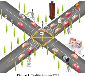
Vehicular ad-hoc networks make it possible for vehicles to communicate amongst themselves, thereby sharing important information like traffic congestions and accidents and ensuring timely response for the same. The traffic communication system consists of vehicles which include vehicles OBU (on board units), Vehicle to vehicle communication, vehicle to RSU communication and RSU to cloud communication. See Figure 1. The proposed model has been based upon the congestion detection and avoidance model, which is used to avoid the congestion conditions that occur due to any accident, road destruction, avalanche and traffic jams.
Figure 1. Traffic System [21]
In this system, if congestion based on VCI which is vehicle congestion index is found, then information is shared with other vehicles and RSU. Based on this congestion, a re-routing mechanism will check alternate routes available, based on remaining number of available roads. Rrem.{Rid-1, Rid-2, Rid-3, Rid-3.... Rid-n,}.Then information is given to the other vehicles to re-route according to optimal path. The sequence diagram of the MRGM is described in figure 2. In this, traffic information is collected through vehicles and
congestion is found through VCD (vehicle congestion density). The road weight calculation is done through PWC in order to find updated weights for finding the optimal path for vehicles.
Figure 2. Sequence diagram of MRGM
4.
Methodology
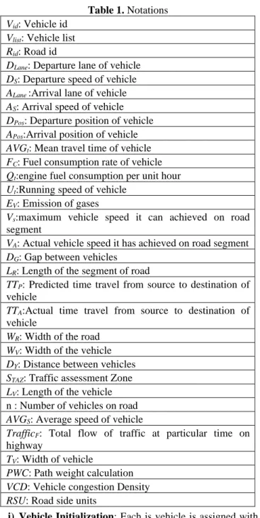
mechanism which provides the vehicle with information of finding the optimal route in case of congestion. There are various notions that have been used in explaining equations. It is defined in table 1.
Table 1. Notations Vid: Vehicle id
Vlist: Vehicle list
Rid: Road id
DLane: Departure lane of vehicle
DS: Departure speed of vehicle
ALane :Arrival lane of vehicle
AS: Arrival speed of vehicle
DPos: Departure position of vehicle
APos:Arrival position of vehicle
AVGt: Mean travel time of vehicle
FC: Fuel consumption rate of vehicle
Qt:engine fuel consumption per unit hour
Ut:Running speed of vehicle
EV: Emission of gases
Vs:maximum vehicle speed it can achieved on road
segment
VA: Actual vehicle speed it has achieved on road segment
DG: Gap between vehicles
LR: Length of the segment of road
TTP: Predicted time travel from source to destination of
vehicle
TTA:Actual time travel from source to destination of
vehicle
WR: Width of the road
WV: Width of the vehicle
DY: Distance between vehicles
STAZ: Traffic assessment Zone
LV: Length of the vehicle
n : Number of vehicles on road AVGS: Average speed of vehicle
TrafficF: Total flow of traffic at particular time on
highway
TV: Width of vehicle
PWC: Path weight calculation VCD: Vehicle congestion Density RSU: Road side units
i) Vehicle Initialization: Each is vehicle is assigned with vehicle id (Vid) which is used to identify the location of the vehicle on the road. In this MRGM collects the information of vehicles which includes the current position of vehicle, its destination preferences, its longitude and latitude. The vehicle will travel along the predefined route initially. Vehicle attribute can be defined as vehicle information: Vid|Rid|DLane|DS|Alane|AS|DPos|APos. Rid defines the id of the road the vehicle shall drive along. DLane, DPos Alane and APos defines the lane on which vehicle is departed and arrived and position of its departure and arrival whereas DS and AS represents departure and arrival speed.
ii)Collection of Information related to Vehicles: While vehicles travel on the roads, the MRGM collects the operational information of from sensors deployed on vehicles, which includes average mean speed of vehicle (AVGs), average mean travel time (AVGt), Fuel consumption
rate(FC) and Vehicle gases emission Value (Ev) which includes CO2, CO and NOX values. The gases emitting from vehicles will help in determine current state of pollution level on particular segment of road.
iii) Traffic states determination: In order to analyze the congestion condition MRGM mechanism uses the multi-metric parameter system which includes various factors of inclusion like Width of road (WR), Length of road(LR), Width of vehicles(WV), Length of vehicle(LV). Based on above parameters, a report is generated which is defined as traffic flow report for n number for vehicles on particular road segment TrafficF: n| AVG s| AVG t| Fc| Ev| WR| LR| WV| LV| is the concatenate of all values. After generating the traffic flow report the information is shared with all vehicles and road side units (RSU) on the particular road segment.
a) Traffic flow rate can be determined with average speed of vehicle on particular road segment which is calculated as
AVGs = 1
𝑛∑ 𝑣
𝑛
𝑖=1 s (1) Here n is number of vehicles and Vs is speed of each vehicle. b) Vehicle density on particular road segment is calculated with two formulas
∑𝑛 𝑊
𝑖=1 v+DG (2) (∑ in=1 LR)+ DY (3)
Here DG is the gap between the vehicles and DY is the distance between vehicles.
c) The traffic condition in MRGM is calculated in two ways:
• Bottleneck Condition: The condition that occurs when area(width) of road covered by multiple vehicles that wants to pass from road is defined as.
∝=[∑𝑛 𝑊
𝑖=1 v+DG]/WR (4) • Accidental or Jam Condition: The traffic condition that
occurs due to any accident or any type of jam that can happen on road from last 300seconds is defined as
∅=[∑𝑛𝑖=1𝐿R+DY]/(LV*n) (5) Here ∝ and ∅ and two functions that define congestion
condition based on width of road and length of the road∝ and ∅.
d) Now the predicted time travel of vehicle on particular lane of road on a given segment is calculated as:
TTP=(𝐿𝑅𝐽)/𝑉𝑉𝑠 𝐽
(6) Here 𝐿𝑅𝐽 defines length of road (R) with its road segment (J).
𝑉𝑉𝑠𝐽 is speed of vehicle it can achieved on road segment J Total time travel from source to destination of vehicle which involves multiple roads is calculated as:
TTt = ∑𝑞𝑖=1 (∑𝑚𝑖=1TTP) (7) Where q represents the remaining number of roads and m represents the segments divided on the road on which vehicles are passing.
Actual time of vehicle is TTA which is calculated by using TTA=(𝐿𝑅𝐽)/𝑉𝑉𝑘
𝐽
(8) Where 𝑉𝑉𝑘𝐽is speed of vehicle, it achieves actually during the travel
Now we define a function 𝜃={∑𝑞𝑖=1 (∑𝑚 TT
𝑖=1 A)}/∑𝑞𝑖=1 (∑𝑚𝑖=1TTP)} (9) It calculates the predicted time requires for vehicle to travel and actual time it has taken to travel on a given route. Stopwatch is used to calculate the actual travel time
The fuel consumption on given road and particular segment can be calculated as:
FC=∑𝑞𝑖=1 (∑ 𝑄𝑡 𝑈𝑡 𝑚
Where FCR is fuel consumption rate, Qt is engine fuel consumption per unit hour(kg/h) and Ut is running speed of vehicle in (Km/hr.).
iv) Traffic congestion analysis: In the MRGM, three parameters∝,∅ and 𝜃 are calculated for traffic states determination. Based on the following parameters, the following table is used to classify the vehicle classification index
Table 2. Vehicle congestion index Vehicle Congestion Index(VCI) Traffic state level
(0.0-0.3) Free flow
(0.3-0.5) Low congestion
(0.5-0.75) Moderate congestion
(0.75-1.0) High congestion
In MRGM, the cases are designed for traffic congestion analysis. The information collected is passed on to RSU nodes in order to analyze the traffic condition of an area which is called as (Traffic Assessment zones) TAZ.
Case1: The congestion occurs when width of the road is equal or less than the number of vehicles passing on the road section
STAZ{ ∝<=∑ 𝑊𝑛𝑖 v+DG]/WR } ( 11) Case2: The congestion happens due to accident or traffic jams the length of road is occupied by the vehicles in particular lane.
STAZ {∅<=[∑ 𝐿𝑛𝑖 R+DY]/(LV*n) } (12) Case 3: If predicted travel time of vehicles is less than actual time travel on the route ,then this is the condition of
congestion occurrence.
STAZ {𝜃 <={∑qi (∑ TTmi A)}/ ∑qi (∑ TTmi P) } (13) The algorithm 1 to check vehicle flow density and
congestion detection is explained below. In this various conditions are explained through which congestion can occur.
Algorithm 1: Algorithm for congestion detection 1: Procedure for Congestion Detection
2: Collect the information of inflow and outflow of traffic data
3: Predicting the count of vehicle after every 300seconds. 4: Calculating the Average Length and Width of vehicles 5: Calculating the Width of Road
6: Calculating congestion condition 1 7: WR less than or equal to ∑𝑛𝑖=1𝑊v+DG
8: Calculating congestion condition 2
9: (LV )*n less than or equal to (∑ni=1 LR)+ DY
10:Calculate congestion condition 3
11:Travel time of vehicle Actual and predicted: 12:TTA / TTP
13:Measure Traffic assessment Zone ST AZ
14:Calculate vehicle congestion density (VCD)
v) Congestion Control: If congestion is detected based on conditions equations 11,12 and 13then congestion control mechanism is initiated. The RSU calculates the Traffic assessment zone(TAZ) of a area. After this K number of routes will be calculated. Each road constitutes edges and lanes. These are assigned with edge id and lane id. The weights are assigned to each segment of road. The RSU determine the shortest optimal path for vehicles. RSU will calculate the PWC (Path weight calculation) of road network. The PWC is calculated as
(PWC) = Wij(∝,∅,θ) (14) It calculates the weight between edges of roads. If
congestion is found then order to find alternate short route the equation is written below
Wij = min(Wij , Wik + Wkj) (15) The algorithm 2 for congestion control is defined below a
Algorithm 2: Algorithm for congestion control Procedure: Collect the information of flow of traffic 1: Create graph of road network (Rid1 , Rid2....Ridn)
2: while SIMULATION do
3: if Simulation Time 600 s == 0 then 4: Pause Simulation
5: STAZ(t) Traffic assessment zone( Graph)
6: Send message to STAZ(t) to RSU to calculate PWC
7: For each road 8: Calculate VCD 9: If congestion found 10: Calculate new path 11: Vlist
12: Shortest path ( Subgrapgh) 13: Wij = min(Wij , Wik + Wkj)
14: For all vehicles in vehicle in VList do
15: CurrentPos Current position of vehicle on road
16: Last pos Last position of vehicle on road
17: Shortest- Paths(subgraph,Current, last) 18: Message(CurrentPos, LastPos)
19: NewPathSet new path
20: Message new path to vehicles on congested roads 21: End
5.
Simulation and Results
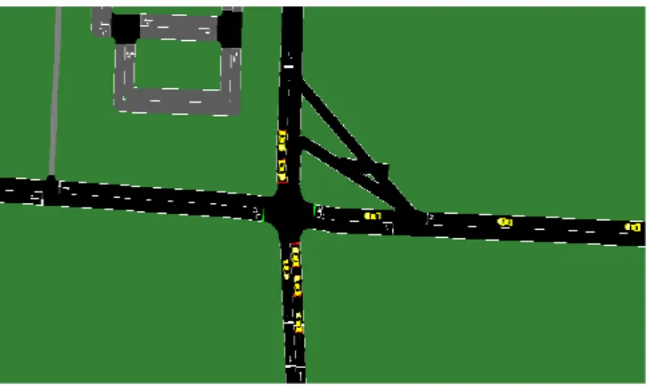
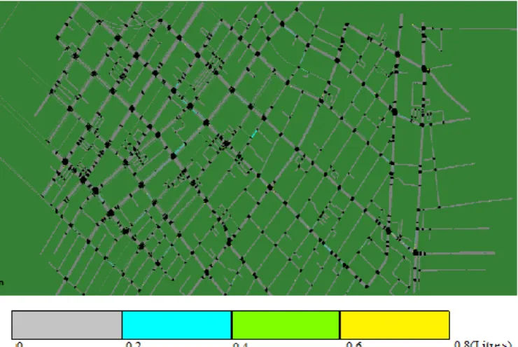
To simulate MRGM mechanism SUMO simulator is used which is an urban mobility traffic simulator with python script. In order to analyze the mechanism, open street maps of Downtown Los Angeles in USA, Melbourne region in Australia and Manhattan in USA are analyzed. The communication radius of RSU is 500 m. The simulation diagram for Los Angeles road map is shown in figure 3
Figure 3. Simulation diagram
The various attributes of the vehicle used in sumo simulator is define below in table 3.
Table 3: Attributes of vehicles Acceler-
ation
Decele- ration
Min gap
Length of vehicle
Emission class Max Speed 2.60ms-2 4.50 ms-2 2.50m 5m HBEFA3/PC_G_
EU4
(Vehicle congestion density) function which varies from 0 to 1. As value of VCD increases, travel time also increases. It means when congestion increases, then average travel time also increases.
Figure 4. Average Travel time
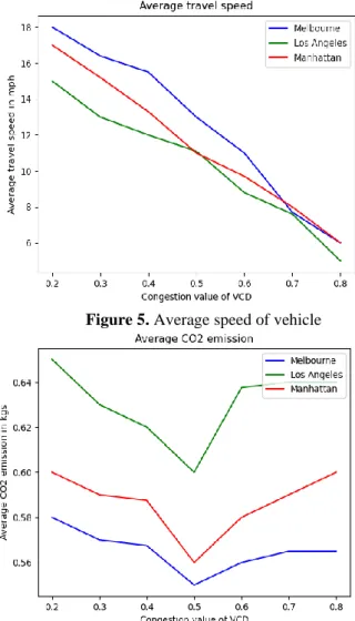
In Figure 5 the effect of average speed of vehicle with VCD is defined. With increase in traffic density, the speed of vehicles decreases. In Figure 6 average CO2 emission level is calculated. In figure 7 average fuel consumption of vehicles is measured with respect to VCD. The fuel consumption is calculated by speed of vehicles and length of road on which vehicles are running.
Figure 5. Average speed of vehicle
Figure 6. Average CO2 emission
Figure 7. Average Fuel consumption
In Figure 8 the travel speed of vehicles is showed on Los Angeles map using MRGM. It has been found that when MRGM mechanism is used, then average speed of vehicles in urban area of Los Angeles is increased which reduces the travel time. Figure 9 shows the CO2 emission on Los Angeles map. The CO2 emission is less as there is less traffic jams and congestion occurs. Figure 10 shows the average fuel consumption by vehicles
Figure 8. Average speed of vehicle on Los Angeles map
Figure 10. Average fuel consumption on Los Angeles map The working of MRGM is compared with existing mechanisms like RTS, SSRGS and Refocus over three different urban areas. The comparison is done based on average fuel consumption, CO2 emission levels and average travel time. The results show that MRGM has shown improved and promising results over these existing techniques and mechanisms. The Figure 11 shows that level of emission of CO2 is reduced by using MRGM as compared to other mechanisms. The figure 12 shows the average fuel consumption which is reduced by using MRGM. The travel time for vehicles has also been reduced which is shown in figure 13. This is due to congestion detection and avoidance mechanism used by MRGM using the functions VCD and PWC for optimal route finding.
Figure 11. Average CO2 emission
Figure 12. Average fuel consumption
Figure 13. Average travel time
6.
Conclusion
This paper proposed a mechanism named as MRGM which is multi-metric traffic congestion detection and avoidance mechanism for urban areas traffic conditions. Here a function (VCD) which is vehicle congestion density is used for measuring the traffic density based on which congestion conditions are defined. The PWC is path weight calculation which is used for understanding the conditions of roads, lanes and edges. With this mechanism, the average travel time on roads for vehicles has been reduced, fuel consumption is significantly lessened and CO2 emission levels are also controlled. This mechanism detects the congestion and also provides rerouting for vehicles with optimal paths by setting new paths to vehicles. The Simulation results show that it has improvement over existing mechanisms in terms of vehicle fuel consumption, vehicle travel time and emission of gases.
References
[1] WHO | Global Status Report on Road Safety, World Health Organization.Available:http://www9.who.int/violence_injury _prevention/road_safety_status/2018.
[2] Urban Mobility Scorecard and Appendices—Urban Mobility Information. Available:https://mobility.tamu.edu/umr/2017. [3] J. Lin, W. Yu, X. Yang, Q. Yang, X. Fu and W. Zhao, "A
Real-Time En-Route Route Guidance Decision Scheme for Transportation-Based Cyberphysical Systems," in IEEE Transactions on Vehicular Technology, vol. 66, no. 3, pp. 2551-2566 , doi: 10.1109/TVT.2016.2572123, 2017. [4] Q. Song and X. Wang, "Efficient Routing on Large Road
Networks Using Hierarchical Communities," in IEEE Transactions on Intelligent Transportation Systems, vol. 12, no. 1, pp. 132-140, doi: 10.1109/TITS.2010.2072503, 2011, [5] C. Sommer, “Shortest-path queries in static networks,” ACM
Computing Surveys, vol. 46, no. 4, pp. 1–31, 2014.
[6] G. Malewicz, M. H. Austern, A. J. Bik, J. C. Dehnert, I. Horn, N. Leiser, and G. Czajkowski, “Pregel,” Proceedings of the 2010 international conference on Management of data - SIGMOD 10, 2010.
[7] G. Owojaiye and Y. Sun, “Focal design issues affecting the deployment of wireless sensor networks for intelligent transport systems,” IET Intelligent Transport Systems, vol. 6, no. 4, pp. 421–432, 2012.
[8] J. Jeong, H. Jeong, E. Lee, T. Oh, and D. H. C. Du, “SAINT: Self-Adaptive Interactive Navigation Tool for Cloud-Based Vehicular Traffic Optimization,” IEEE Transactions on Vehicular Technology, vol. 65, no. 6, pp. 4053–4067, 2016. [9] H. Noori and B. B. Olyaei, “A novel study on beaconing for
area using 802.11p,” 2013 International Conference on Smart Communications in Network Technologies (SaCoNeT), 2013. [10] H. Noori, L.Fu, and S. Shiravi, “A connected vehicle based traffic signal control strategy for emergency vehicle preemption,” in Proc. Transp.Res.Board 95th Annu. Meeting, nos. 6716-6763, pp. 1-14, 2016.
[11] S. Wang, S. Djahel, Z. Zhang, and J. Mcmanis, “Next Road Rerouting: A Multiagent System for Mitigating Unexpected Urban Traffic Congestion,” IEEE Transactions on Intelligent Transportation Systems, vol. 17, no. 10, pp. 2888–2899, 2016.
[12] W. Balid, H. Tafish, and H. H. Refai, “Intelligent Vehicle Counting and Classification Sensor for Real-Time Traffic Surveillance,” IEEE Transactions on Intelligent Transportation Systems, vol. 19, no. 6, pp. 1784–1794, 2018. [13] S. Wang, S. Djahel, and J. Mcmanis, “An adaptive and
VANETs-based Next Road Re-routing system for unexpected urban traffic congestion avoidance,” IEEE Vehicular Networking Conference (VNC), 2015.
[14] Y. Zeng, D. Li, and A. V. Vasilakos, “Opportunistic fleets for road event detection in vehicular sensor networks,” Wireless Networks, vol. 22, no. 2, pp. 503–521, 2015.
[15] M. Berlin, S. Anand, “Direction based Hazard Routing Protocol (DHRP) for disseminating road hazard information using road side infrastructures in VANETs,” Springer plus 3(1):173, 2014.
[16] M. Sepulcre, J. Gozalvez, O. Altintas, and H. Kremo, “Integration of congestion and awareness control in vehicular networks,” Ad Hoc Networks, vol. 37, pp. 29–43, 2016. [17] S. G. Manyam, S. Rathinam, S. Darbha, D. Casbeer, and P.
Chandler, “Routing of two Unmanned Aerial Vehicles with communication constraints,” 2014 International Conference on Unmanned Aircraft Systems (ICUAS), 2014.
[18] N. Akhtar, S. C. Ergen, and O. Ozkasap, “Vehicle Mobility and Communication Channel Models for Realistic and Efficient Highway VANET Simulation,” IEEE Transactions on Vehicular Technology, vol. 64, no. 1, pp. 248–262, 2015. [19] S. Bitam, A. Mellouk, and S. Zeadally, “VANET-cloud: a
generic cloud computing model for vehicular Ad Hoc networks,” IEEE Wireless Communications, vol. 22, no. 1, pp. 96–102, 2015.
[20] A. S. Khan, K. Balan, Y. Javed, S. Tarmizi, and J. Abdullah, “Secure Trust-Based Blockchain Architecture to Prevent Attacks in VANET,” Sensors, vol. 19, no. 22, p. 4954, 2019. [21] A. Nayar, R. S. Batth, D. B. Ha, and G. Sussendran, G.
“Opportunistic networks: Present scenario-A mirror review”InternationalJournal of Communication Networks and Information Security,” 10 (1), pp. 223-241, 2018.
[22] R. S. Batth, M. Gupta, K. S. Mann, S. Verma, and A. Malhotra, “Comparative Study of TDMA-Based MAC Protocols in VANET: A Mirror Review,” Advances in Intelligent Systems and Computing International Conference on Innovative Computing and Communications, pp. 107–123, 2019.
[23] H. Sadeghian, A. Farahani, M. Abbaspour, “Overheadcontrolled contention-based routing for VANETs”, International Journal of Communication Networks and Information Security, Vol. 6, No. 2, August 2014.
[24] J. Harri, F. Filali, and C. Bonnet. Mobility models for vehicular ad hoc networks: a survey and taxonomy. IEEE Communications Surveys Tutorials, 11(4):19–41, 2009. [25] N. Alam and A. G. Dempster. “Cooperative positioning for
vehicular networks: Facts and future.”IEEE Transactions on Intelligent Transportation Systems, 14(4):1708–1717, 2013. [26] R. Singh and K. S. Mann, “Improved TDMA Protocol for
Channel Sensing in Vehicular Ad Hoc Network Using Time Lay,” Proceedings of 2nd International Conference on Communication, Computing and Networking Lecture Notes in Networks and Systems, pp. 303–311, 2018.
[27] S. R. Azimi, G. Bhatia, R. (R. Rajkumar, and P. Mudalige, “Vehicular Networks for Collision Avoidance at
Intersections,” SAE International Journal of Passenger Cars - Mechanical Systems, vol. 4, no. 1, pp. 406–416, 2011. [28] A. K. Sandhu, R. Singh Batth and A. Nagpal, "Improved
QoS Using Novel Fault Tolerant Shortest Path Algorithm in Virtual Software Defined Network (VSDN)," International Conference on Automation, Computational and Technology Management (ICACTM), London, 2019, pp. 383-388, doi: 10.1109/ICACTM.2019.8776762.
[29] N. S. Vishnu, R. Singh Batth and G. Singh, "Denial of Service: Types, Techniques, Defence Mechanisms and Safe Guards," International Conference on Computational Intelligence and Knowledge Economy (ICCIKE), Dubai, United Arab Emirates (UAE), 2019, pp. 695-700, doi: 10.1109/ICCIKE47802.2019.9004388.