TECHNICAL UNIVERSITY OF CLUJ-NAPOCA
ACTA TECHNICA NAPOCENSIS
Series: Applied Mathematics, Mechanics, and Engineering Vol. 61, Issue II, June, 2018
RESEARCH REGARDING A METHOD FOR DETERMINING THE
PARAMETERS VALUE OF MODIFYING SPUR GEARS TEETH PROFILE
IN LONGITUDINAL PLANE
Mircea MERA, Cristina MIRON-BORZAN
Abstract: The paper presents aspects related to a proposed method for determining the parameters value of modifying spur gears teeth profile in longitudinal plane. Numerical research for a spur gear asymmetrical positioned against the bearing, under the influence of some execution, assembly and functioning errors are presented.
Key words: spur gears, teeth profile, crowning, numerical simulation, fine element, study case.
1. INTRODUCTION
The objective of the gear drive is to transmit power with comparatively smaller dimensions, runs reasonably free of noise and vibration with least manufacturing and maintenance cost [1].
An abrupt change in the cross-section may acts as the stress raiser leading to stress concentration and increases the amount of localized stress, or can decrease the transmission error and smooth engaging and much more [2].
Interactions between tooth modifications and profile error must be studied, even if profile modifications and profile errors are micro-geometrical, they have considerable effects on vibrations of gear pair [3].
The geometry of spur gear tooth profile is based on involute curve. Involute curve is the trace of the end point of the wire unwounded from the circle called the base circle. Every spur gear has some characteristic parameters [4]
Modification of the teeth by crowning increases the load capacity of the gear because it reduces the concentration of the specific stresses that occur at the tooth margins of the gear. This it can be due to its finite length and allows to obtain a corresponding contact patch
(as shape and position on the flank), due to the compensation of the operating errors, or due to the elastic deformation of the shafts and gears, as well the manufacturing and assembly errors. This modification is recommended for highly loaded gears.
2. THE PRINCIPLE OF THE METHOD
The method is based on the use of a finite element analysis program (ALGOR) and aims to assess the parameters value of modifying the tooth in the longitudinal plane by the construction of a shape elastically deformed of the gear tooth at a combined bending - torsion stress.
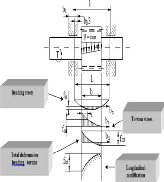
constructed (Figure 1). The mirror image represents the initial shape that the gear tooth will need to have, so that under the action of the stresses from engagement, its behavior in the working stage to be suitable. Then the tooth shape will be approximated by technological curves, so that the tooth to can be manufactured.
It is recommended that for each gear, the 3D model or the solid model to be made, that can be then subjected to finite element analysis.
Fig. 1. The elastic deformation of the pinion- shaft
The notations used in Figure 1 have the following meanings:
• fix - is the deformation of the gear tooth at bending, at a x distance from the front surface of the tooth;
• ftx - is the deformation of the gear tooth at torsion, at a x distance from the front surface of the tooth;
• ftot - the total deformation of the gear tooth due to its bending and torsion
• T - the achieved torque • bL - the bearing width
• b - the width of the gear teeth
• p – the specific applied force [N/mm]
3. NUMERICAL RESEARCHES
Finite Element Analysis aims to determine the value of the parameters required for the longitudinal modification of the cylindrical spur gear teeth profile.
The Finite Element Analysis algorithm (Figure 2) starts from the spur gears teeth profile which will be subjected to changes in longitudinal plane. The gear tooth profile was obtained using the MAIN.CPP program.
The gear model was exported as DXF files for the ALGOR finite element analysis software.
Fig. 2. Block diagram of the FEM analysis algorithm
It has been considered a cylindrical spur gear, with z=30 teeth, module m=4 mm, loaded with 1500 N linear force distributed over the teeth, asymmetrically mounted on a shaft, that is sustained onto two bearings. The spur gear is considered to be made of alloy steel, 41MoCr10.
Numerical research was carried out by applying FEM to determine the influence of manufacturing, assembly and functioning errors
PROGRAM ALGOR
Gets the DXF files with the
gear’s model
Realizes the 2D discrete
model of the gear
PROGRAM ALGOR
The 3D discrete model is built
The boundary conditions are
impose
The loading with forces
The computation of stresses
and elastic strains
PROGRAM MAIN.CPP
Computes the point on the
Gear profile
on the correction depth of tooth gear (flank or correction depth) mounted asymmetrically between bearings.
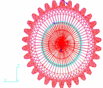
The 3D meshed of the toothed wheel was made (Figure 3).
Fig. 3. Front view of the 3D discrete model
The spur gear-shaft model is the same, which was used to set the correction parameters for the head of the gear teeth (tip relief) [5] for the case when the spur gear is mounted on the shaft in asymmetric position, against the bearings. The torque applied was 56.3815 Nm, corresponding to a transmission power of 8.9 kw at 1500 rpm. These values are typical for a real potential situation, in which the formed gear with the chosen spur gears can work.
In the case of teeth with modifications in the longitudinal profile (crowning), the loading is made with parabolically distributed forces, to obtain an uniform load distribution on the teeth width, thus decreased effect for concentration of the load on the teeth margins.
Two situations were considered: bcal < b and bcal > b.
When bcal <b, the gear with dished teeth is slightly loaded and / or the total deviation of the tooth direction has a high value, the elastic deformed teeth corresponding to this situation are presented in Figure 4.
Fig. 4. The elastic deformed tooth model bcal < b
Fig. 5. The elastic deformation of gear tooth
The maximum value is recorded in the node located in the middle of the gear tooth.
The representation of the curve for elastic deformations of the gear tooth is shown in Figure 5. Where, R232 means: R-Spur gear, 2- asymmetrically positioned between the bearings, 3-parabolic loaded, 2-case b>bcal.
Fig. 6. The elastic deformed tooth model bcal > b
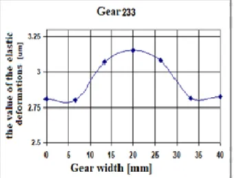
The maximum elastic deformation value is determined in the node located in the middle of the gear tooth.
The graphical representation of the elastic deformations of the gear tooth in the case of loading with parabolic forces is shown in Figure 7. Where, R233 means: R-Spur gear, 2-asymmetrically positioned between the bearings, 3-parabolic loaded, 3-case b<bcal.
On the basis of the proposed method, the parameters value of the axial profile modification were determined and were 2.5 and 2.6 µm for the depth crowning, the length of the modification were 13.3 mm and 13.4 mm respectively.
The modified tooth in the longitudinal plane is shown in Figure 8. It can be considered to have a symmetrical crowning.
Fig. 7. The elastic deformation of gear tooth
Fig. 8. The shape of tooth modified in axial plane
4. CALCULATION OF THE
REPARTIONION FOR PARABOLIC
DISTRIBUTED LOADING OVER THE TOOTH WIDTH
The load distribution is further determined on the tooth width when the force is parabolically distributed.
It is considered a function of the form
p(x)=mx2+nx+r, which describes the parabolic
evolution of force on the width b of the gear tooth.
Case b > bcal
The b > bcal situation is considered, when, where i fulfills the condition i < n-1 subintervals (figure 9).
Fig. 9. Parabolic distribution of forces for the case b < bcal
The recurrence formula is:
3
2 2
]} ) 1 ( ) 1 ( [ 2 )] 1 ( [ 3 {
i
k k
k k k
k F
Fk = + − − + − + −
where: k is the subinterval number for which the calculation is made.
The forces concentrated in the network nodes on the bcal are calculated with:
The force in node 1:
2 2 ) 2 3 ( 1 3 ) 1 ( F i i F
F = − = (2)
The force in node 2:
2 2 2 1 ) 2
( F F
F = + (3)
The force in node k is:
2 2
1 )
(k Fk Fk
F = − + (4)
The force in node n is:
2 1 ) ( − = n n F
F (5)
For the presented case it was considered: n = 7 nodes, n-1 = 6 subintervals, and i = 4.
Case b < bcal
It is characterized by b < bcal (
1 − = n b i
bcal ),
where i fulfills the condition i > n-1 subintervals (figure 10).
The recurrence formula for the k subinterval becomes: 3 2 2 ]} ) 1 ( ) 1 ( [ 2 )] 1 ( ( 3 {[ i k k k k k k F
Fk = + − − + − + −
(6)
Corresponding to this situation, i = 8 subintervals was considered, for the achieved models, which describe this situation.
Fig. 10. Parabolic distribution of forces for the case b < bcal
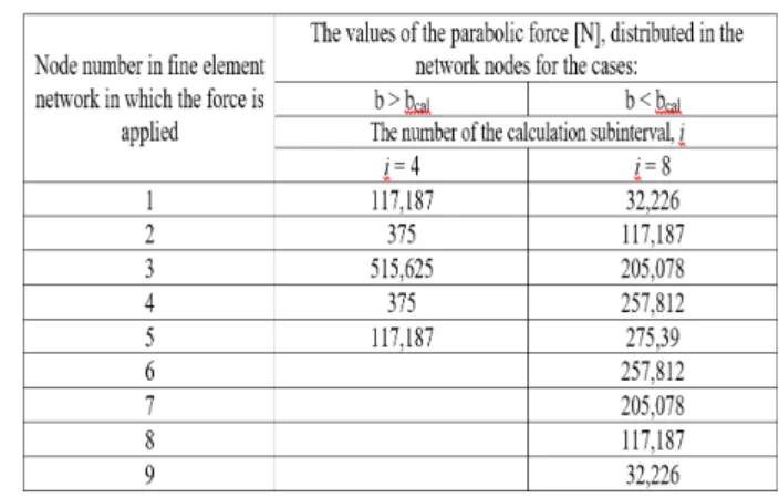
The values of distributed parabolic forces, applied in the nodes of the finite element network, for the cases considered in the MEF analysis and calculated with the relationships defined above, are shown in Table 1
Table 1
The value of parabolic distributed forces, for cases b > bcal, b < bcal
6. CONCLUSION
In this paper research regarding the way of determining the parameters value of modifying spur gears teeth profile in longitudinal plane were presented (crowning).
The current research is a part of a wide reaserch and in this part is presented the method of determining the value of the crowning parameters of the spur gear tooth flank in the case of real potential situations.
A spur gear asymmetrical positioned against the bearings was considered.
behavior of the proposed gears were also made. The deformed spur gear teeth profiles and their variants are presented in accordance with existing technological possibilities so that a proper throw in gear is made during operation.
Future research will be oriented to allow the establish of:
• the influence of the position of the spur gears against the bearings, on the parameters value for longitudinal modification of the teeth profile.
• the influence of execution, assembly and functioning errors on the parameters value for longitudinal modification of the teeth profile.
8. REFERENCES
[1] Sankar S., Sundar Raj M., Nataraj M., Profile Modification for Increasing the Tooth
Strength in Spur Gear Using CAD,
Engineering, 2, 740-749, 2010.
[2] Paul I. D, Bhole G.P., Modification of Spur Gear Using Computational Method-Involutes Profile Being Modify, Proceedings of the
International Conference on Industrial
Engineering and Operations Management
Dhaka, Bangladesh, 2010.
[3] Divandari M., Aghdam B. H., Barzamini R.,
Tooth Profile Modification and its Effect on Spur Gear Pair Vibration in Presence of
Localized Tooth Defect, Journal of
Mechanics, Vol. 28, Issue 2, pp. 373-381, 2012.
[4] Sobiepański M., Nieszporek T., Spur gears with
longitudinal tooth profile modification mesh creating which is suitable for stress analysis, Technical Gazette 24, p. 1657-1660, 2017.
Gyenge, C., Mera, M., Researchs on cylindrical
gearing with high precision, Research project 5003/1996.
[4] Mera, M., Gyenge, C. & Comsa, S, The study of
the deformations under loads of the outer cylindrical gears, Second International Conference MTeM, Cugir, 14-16 October, 1993.
[5] M.Mera, C. Miron-Borzan, Research Regarding
the Influence of Execution, Assembly and Functioning Errors on the Teeth Profile Modification of Spur Gear in Front Plane, MATEC Web of Conferences 137, 01007, 2017.
[6] Mera, M., Gyenge Cs., Comşa S., Mera O.
Research concerning the influence of some mounting errors upon the shape and position of the path of contact for spur gear drives, 6th. International DAAAM Symposium, Krakow, pag. 227-228, Poland, 26-28th. october, 1995.
[7] M. Mera, Gyenge Cs., Comşa, S, Gears with
Profile Crowning and Flanking, International DAAAM Symposium Cluj-Napoca, România, 22 – 24 th. October, 1998.
Cercetari asupra unei metode de determinare a modificărilor de profil a dinţilor roţilor dinţate cilindrice cu dinţi drepţi in plan longitudinal
Lucrarea prezintă aspecte legate de o metodă propusă pentru determinarea valorii parametrilor modificării profilului dinţilor roţilor dinţate cilindrice în plan longitudinal. Sunt prezentate cercetări numerice pentru o roată dinţată cilindrică, asimetric poziţionată faţă de lagăre, sub influenţa unor erori de funcţionare, de execuţie şi montaj.
Mircea MERA, PhD, Assoc. Prof., Technical University of Cluj-Napoca, Department of Manufacturing Engineering, [email protected], 0264401729, Bdul Muncii no 103-105, Cluj-Napoca, Romania.