A Comparison of Application-Level and
Router-Assisted Hierarchical Schemes
for Reliable Multicast
Pavlin Radoslavov, Christos Papadopoulos
, Member, IEEE
, Ramesh Govindan, and Deborah Estrin
, Fellow, IEEE
Abstract—One approach to achieving scalability in reliable mul-ticast is to use a hierarchy. A hierarchy can be established at the application level, or by using router-assist. With router-assist we have more fine-grain control over the placement of error-recovery functionality, therefore, a hierarchy produced by assistance from the routers is expected to have better performance. In this paper, we test this hypothesis by comparing two schemes, one that uses an application-level hierarchy (ALH) and another that uses router-as-sisted hierarchy (RAH). Contrary to our expectations, we find that the qualitative performance of ALH is comparable to RAH. We do not model the overhead of creating the hierarchy nor the cost of adding router-assist to the network. Therefore, our conclusions in-form rather than close the debate of which approach is better.
Index Terms—Reliable multicast, router-assist for reliable multicast.
I. INTRODUCTION
R
ELIABLE multicast has received significant attention re-cently in the research literature [1]–[8]. The key design challenge for reliable multicast is scalable recovery of losses. The two main impediments to scale areimplosionandexposure. Implosion occurs when, in the absence of coordination, the loss of a packet triggers simultaneous redundant messages (requests and/or retransmissions) from many receivers. In large multicast groups, these messages may swamp the sender, the network, or even other receivers. Exposure wastes resources by delivering a retransmitted message to receivers which have not experienced loss. Another challenge that arises in the design of reliable mul-ticast is longrecovery latency, which may result from suppres-sion mechanisms introduced to solve the implosuppres-sion problem. Latency can have significant effect on application utility and on the amount of buffering required for retransmissions.One popular class of solutions ishierarchical data recovery. In these schemes, participants are organized into a hierarchy.
Manuscript received April 12, 2002; revised May 28, 2003; approved by IEEE/ACM TRANSACTIONS ONNETWORKINGEditor S. Paul. This work was supported by the National Science Foundation under Cooperative Agreement NCR-9321043. Any opinions, findings, and conclusions or recommendations expressed in this material are those of the authors and do not necessarily reflect the views of the National Science Foundation.
P. Radoslavov is with the International Computer Science Institute, Berkeley, CA 94704 USA (e-mail: pavlin@icsi.berkeley.edu).
C. Papadopoulos and R. Govindan are with the Computer Science Depart-ment, University of Southern California, Los Angeles, CA 90089-0781 USA (e-mail: christos@isi.edu; ramesh@usc.edu).
D. Estrin is with the Department of Computer Science, University of Cali-fornia, Los Angeles, CA 90095 USA (e-mail: destrin@cs.ucla.edu).
Digital Object Identifier 10.1109/TNET.2004.828950
By limiting the scope of recovery data and control messages between parents and children in the hierarchy, both implosion and exposure can be substantially reduced. Hierarchies intro-duce a latency penalty, but that is proportional to the depth of the hierarchy. The biggest challenge with hierarchical solutions is the construction and maintenance of the hierarchy, especially for dynamic groups. For optimal efficiency, the recovery hier-archy must becongruentwith the actual underlying multicast tree.1 Divergence of these structures can lead to inefficiencies
when children select parents who are located downstream in the multicast tree.
One approach, exemplified by reliable multicast transport protocol (RMTP) [3], is to use manual configuration or application-level mechanisms to construct and maintain the hierarchy. Manual hierarchy construction techniques rely either on complete or partial (e.g., where the border routers are) knowledge of the topology. Automated hierarchy construction techniques rely on dynamically discovering tree structure, either explicitly by tracing tree paths [6], or implicitly by using techniques based on expanding ring search. Once a hierarchy is formed, children recursively recover losses from their parents in the hierarchy by sending explicit negative acknowledgments. Another approach, exemplified by light-weight multicast services (LMS) [2], proposes to use minimal router support not only to make informed parent/child allocation, but also to adapt the hierarchy under dynamic conditions. PGM [9] is another example of a router-assisted approach. In some of these router-assisted schemes, hierarchy construction is achieved by routers keeping minimal information about parents for downstream receivers, then carefully forwarding loss recovery control and data messages to minimize implosion and exposure. In these schemes, hierarchy construction requires little explicit mechanism at the application level at the expense of adding router functionality. Because of this, one would expect these
router-assisted hierarchies (Section II-B) to differ from the
application-level hierarchies (Section II-A) in two different ways: 1) router-assisted hierarchies are finer-grained; that is, have many more “internal nodes” in the hierarchy; and 2) they are more congruent to the underlying multicast tree.
Then, it is natural to ask, as we do in this paper: Is the per-formance of application-level hierarchies qualitatively different than that of router-assisted hierarchies? To our knowledge, this question has not been addressed before. We study this question by evaluating two specific schemes: LMS and an RMTP-like
1Congruency is achieved when the virtual hierarchy and the underlying
mul-ticast tree coincide. 1063-6692/04$20.00 © 2004 IEEE
scheme, which use two specific hierarchy construction tech-niques. For our comparison we used four metrics: recovery latency, exposure, data traffic overhead, and control traffic overhead. We approach the question from two angles: first, we use analysis (Section III) to determine the asymptotic behavior of the two schemes for regular trees, and second, we employ simulation (Section IV) to study the performance of large irregular multicast trees. These irregular multicast trees are randomly generated using various receiver placement models on real-world topologies such as the Internet [10], AS [11], and the Mbone [12] topologies [13], as well as canonical topologies such as random, mesh, and -ary tree.
Before doing this performance comparison, our expecta-tion was that router-assisted hierarchies would significantly outperform application-level hierarchies. Our finding was surprising: that, with careful hierarchy construction, the per-formance of application-level hierarchiesis comparableto that of router-assisted hierarchies, even though the former have a coarse-grained recovery structure. However, as we show, there exist pathological hierarchy construction techniques for which application-level hierarchies perform qualitatively worse than router-assisted hierarchies. Thus, the congruence of the hierarchy to the underlying multicast tree seems to be more important to performance that having a fine-grain recovery structure.
We should emphasize that we model only the essential fea-tures of the two schemes, and while our conclusions may be colored by the specific schemes we chose, we believe our re-sults have a bearing on the larger issue of how router-assisted hierarchies compare to application-level hierarchies. Further-more, our conclusions inform but do not necessarily close the debate regarding the appropriate approach to hierarchical data recovery. Indeed, it is possible to design more advanced applica-tion-level hierarchical schemes that perform better than the par-ticular scheme we use in our study; however, investigating such schemes is beyond the scope of this paper. Finally, our evalua-tion metrics do not capture the complexity and cost of hierarchy construction, or the complexity of adding router-assist for hier-archical recovery to the network.
The rest of this paper is organized as follows. In Section II, we present in detail the application-level and router-assisted schemes we consider in this paper, and describe the evaluation metrics. Section III presents the -ary tree analytical results for both schemes. Section IV presents and discusses the simulation results for the real-network and canonical topologies. Related work and conclusions are in Sections V and VI, respectively.
II. HIERARCHICALMULTICASTDATARECOVERYSCHEMES
As the name implies, hierarchical reliable multicast schemes solve the scalability problem by structuring the multicast group into a hierarchy. Because a hierarchy explicitly enforces scope on the data recovery, it is a natural approach to address many of the problems described earlier, including implosion, exposure and latency. Two classes of hierarchical schemes have been studied in the literature. The first class,application-level hierarchical schemes (ALH), uses only end-to-end mecha-nisms assisted by the end-systems (the receivers) to create
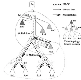
Fig. 1. ALH example: optimal hierarchy organization.
and maintain the hierarchy. The second class, router-assisted hierarchical schemes(RAH), uses assistance from the routers in the creation and maintenance of the hierarchy.
A. Application-Level Hierarchical Schemes
ALH schemes create and maintain the data recovery hierarchy by using only end-to-end mechanisms. Typical mech-anisms include manual (static) configuration and expanding ring search to locate the nearest candidates. More sophisticated schemes employ heuristics like “loss fingerprinting” where receivers compare their loss fingerprints with those of potential parents and select the most appropriate. Both types, however, tend to be slow to adapt to dynamic conditions and are not always accurate in maintaining congruency.
RMTP [3] is an example of an ALH scheme, and forms the basis of our ALH model. RMTP employs a combination of pos-itive and negative acknowledgments (ACK and NACK) for data recovery. Because the focus of this paper is not on modeling and evaluating protocol details, but rather understanding the under-lying mechanisms, we do not precisely model the RMTP pro-tocol; instead, we adopt the hierarchical approach in RMTP and model only NACKs and retransmissions.
Briefly, our ALH scheme works as follows. In Fig. 1, is a parent for , and , while itself is a parent for , and . Upon detecting a loss on link – , children unicast NACKs to their parents ( to , and to .) If the parent has the data it sends it to its children by either unicast or multicast. A multicast response is sent to a local multicast group where only the children and the parent are members of this group. To select between unicast and multicast, a parent collects NACKs and uses multicast if at least 50% of the children requested data retransmission; otherwise the parent uses unicast (parent to .) If a parent does not have the requested data, its own parent also detects the loss from missing acknowledgments (and so on until we reach the root). After receiving the data, each parent sends it to its children.
RMTP does not explicitly specify how the hierarchy is cre-ated; rather, in its current incarnation it assumes a manually con-figured static hierarchy. Obviously, such manual configuration
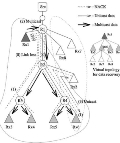
Fig. 2. ALH example: sub-optimal hierarchy organization.
may result in sub-optimal performance (see Fig. 2 for an ex-ample). In order to explore the potential of ALH schemes, we introduce a rather powerful heuristic: we hypothesize that all participants have somehow obtained information about the dis-tance (in number of hops) to each other, and use that information in a heuristic algorithm to create the hierarchy. The algorithm creates the hierarchy in a bottom-up fashion as follows: among a group of participants, the node with the smallest sum of dis-tances to all other nodes becomes a parent. Initially, all receivers are eligible to become parents and thus, the lowest level of the hierarchy is formed by selecting parents among all receivers. Each of the receivers which was not elected as a parent chooses the closest parent node as its parent. The same heuristic is re-cursively applied at the next level among all the nodes that were selected as parents in the previous iteration, until we are left with a small number of nodes which become children of the root of the tree (i.e., the sender). The depth of the hierarchy is defined by the fraction of nodes to choose at each iteration, which is a number in the interval (0.0, 0.5). A value of 0.1 for example means that among all nodes at level in the data recovery hier-archy, 10% of them will become parents of the remaining 90%.
B. Router-Assisted Hierarchical Schemes
Router-assisted hierarchical schemes (RAH) use assistance from the network to achieve congruency between the hierarchy and the multicast tree. By eliminating the need to maintain the hierarchy through potentially expensive and complicated endsystem-based mechanisms, RAH schemes reduce appli-cation complexity and enable the development of large-scale reliable multicast applications. For our evaluation of RAH schemes we chose LMS [2] as our model. LMS employs router-assist to create a dynamic hierarchy which continuously tracks the underlying multicast routing tree regardless of membership changes. The network-assist required by LMS is in the form of new forwarding services at the routers, and thus, has no impact at the transport level. With LMS each router marks a downstream link as belonging to a path leading to a replier. A replier is simply a group member willing to assist with error recovery by acting as a parent for that router’s
immediate downstream nodes. Because they are selected by routers, parents are always upstream and close to their children. The forwarding services introduced by LMS allow routers to steer control messages to their replier, and allow repliers to request limited scope multicast from routers. More specifically, LMS adds the following three new services to routers.
• Replier selection:Potential repliers advertise to the local router their willingness to serve as repliers for a partic-ular(Source, Group)pair. Routers propagate these adver-tisements upstream. Before propagating the message up-stream, a router selects one of its downstream interfaces (based on an application-defined metric) as the replier in-terface. When all routers have received advertisements the replier state is established. Replier state is soft state which provides robustness and guards against replier and link failures.
• NACK forwarding: LMS routers forward NACKs hop-by-hop according to the following rules: a NACK from the replier interface is forwarded upstream; a NACK from a nonreplier interface (including the upstream interface) is forwarded to the replier interface. However, a NACK from a nonreplier downstream interface marks this router as the “turning point” of that NACK. Note that by definition, there can be only one turning point for each NACK but the same turning point may be shared by multiple NACKs. Before forwarding a NACK, the turning point router inserts in the packet the addresses of the incoming and outgoing interfaces, which we call the “turning point information” of the NACK. This information is carried by the NACK to the replier. • Directed multicast (DMCAST): DMCAST is used by
repliers to perform fine-grain multicast. A replier creates a multicast packet containing the requested data and addresses it to the group. The multicast packet is encap-sulated into a unicast packet and sent to the turning point router (whose address was part of the turning point infor-mation) along with the address of the interface the NACK originally arrived at the turning point router. When the turning point router receives the packet, it decapsulates and multicasts it on the specified interface. An enhanced version of DMCAST may allow repliers to specify more than one interface that the packet should be directed to send on.
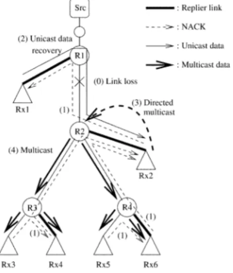
LMS works well in most cases to deliver the requested packet with minimum latency and only to receivers that need it. Fig. 3 shows such an example. The loss on link – is recovered from replier by sending a DMCAST to . However, in some cases LMS may expose receivers to retransmissions that do not need it. This occurs when loss happens on the replier path, as shown in Fig. 4. The resulting exposure does not affect cor-rectness but may lead to wasted resources if a replier branch (the link between and in our example) is particularly lossy. LMS addresses this problem by selecting the replier branch that advertises the least loss. However, determining path loss char-acteristics can be hard, and thus, LMS employs another method to eliminate exposure, which comes at the cost of eventually adding an extra hop to the retransmission. With this enhance-ment, a NACK by a downstream replier specifies that the reply
Fig. 3. LMS vanilla example: data loss and recovery.
Fig. 4. LMS vanilla example: data loss by replier only and exposure to other receivers.
should be unicast to the requestor itself rather than the turning point. For example, in Fig. 5 (the same loss scenario as in Fig. 4) will directly unicast the reply to and therefore, there will be no exposure on the subtrees rooted at and . The extra hop of retransmission can be illustrated by the example in Fig. 6 where the packet loss occurs on the link between and . Similar to the previous example, the request by down-stream replier will reach and the reply will be unicast back to . However, because in the mean time has re-ceived NACKs from the downstream parts of the tree ( and ), now it just needs to send a single enhanced directed multi-cast to specifying that the reply should be multicast on links – and – . Only if later the requestor receives more requests, direct multicasts are sent to the remaining part of the subtree. Note that this two-step process occurs only once, between the replier above the loss and the first requestor. We distinguish the previous version (which we call “vanilla LMS”) from this version, which we call “enhanced LMS.” Preliminary experiments have shown that for large groups the increase in la-tency in enhanced LMS is negligible but there is a significant
Fig. 5. LMS enhanced example: data loss by replier only and unicast recovery.
Fig. 6. LMS enhanced example: two-step data recovery (unicast followed by direct multicast).
reduction in exposure. Therefore, in this paper we use the en-hanced version of LMS.
We note that LMS is not the most aggressive router-assisted recovery scheme. Finer grain recovery schemes, in which routers themselves respond to loss recovery requests from downstream neighbors, can perhaps perform better than LMS. While such schemes are conceivable, we believe they are impractical in that they require significant router state.
C. Metric Space
We did not model the overhead of creating a hierarchy with ALH schemes, because this depends strongly on the tion and network characteristics. For example, in an applica-tion where membership is static, parents can be deployed manu-ally and can yield excellent performance. At the other extreme, applications with mobile receivers may impose many restric-tions on the type of the hierarchy creation algorithm and the parent-child associations.
If we ignore the overhead for creating and maintaining the hi-erarchy, the main source of inefficiency in ALH schemes is the lack of congruency between the possibly fine grain hierarchy
and the underlying multicast tree. Divergence of the two struc-tures results in problems when children inadvertently join par-ents that are located downstream or are too far away, which re-sults in an increase in recovery latency and network overhead. For example, in Fig. 2 receiver is at the very bottom of the multicast delivery tree, but is inadequately a parent for the up-stream , and . RAH schemes do not suffer from these problems because they continuously track the multicast topology (although the cost varies among different schemes).
To evaluate the two schemes, we have defined a set of met-rics which represent the impact of the data recovery mechanism on the application and the network. These metrics are defined below; in Section II-D we will present some examples of those metrics computed for different data recovery schemes.
• Data recovery latency. The recovery latency is defined as the ratio of the data recovery time observed by a receiver to the round-trip time from that receiver to the sender. A smaller value means that the receivers will wait less to re-ceive the missing data. For example, a latency of 0.5 means that the time it will take for the receiver to recover the data is half of the round-trip time to the root/sender. The formula we use to compute the average data recovery latency across all receivers and across all links being lossy is
Number Of Loss Rcvs Number Of Links where is the receiver latency when the packet loss is on link , is the round-trip time from re-ceiver to the root of the tree, Number Of Loss Rcvs is the total number of receivers that have observed any loss, and Number Of Links is the total number of links in the topology. In ALH schemes, latency can increase due to longer recovery paths or multiple hops (parents). RAH schemes typically do not suffer from these problems be-cause they almost always recover from the nearest replier, and they have the capability of sending the multicast data to only one branch of the tree.
• Receiver exposure. The receiver exposure is defined as the ratio of the extra amount of packets that have been received by a receiver (and eventually discarded), to the total number of packets sent by the sender. Ideally, this metric should be 0 (i.e., no extra packets are received and no extra processing is performed by the receivers). The formula we use to com-pute the average receiver exposure is
Number Of Exp Rcvs Number Of Links where is the exposure for receiver (in term of number of extra packets) when the packet loss is on link , Number Of Exp Rcvs is the total number of receivers that have observed any exposure, and Number Of Links is the total number of links in the topology. • Data traffic overhead. The data traffic overhead is
de-fined as the ratio of the amount of used network resources because of the retransmitted multicast data (in term of total number of data packets sent over any link in the network), and the size of the subtree (in number of links) that did not receive the data. In the ideal case the data overhead
will be 1.0 (e.g., when the node right above the lossy link has the data and it sends a single multicast packet down the whole branch of the tree that observes the loss). ALH schemes suffer from this overhead because of the ineffi-ciency introduced by the unicast/multicast combination. The formula we use to compute the average data overhead across all lossy links is
Number Of Links
where is the total amount of data traffic that will be created when the packet loss is on link is the size of the subtree (in term of number of links) that did not receive the data, i.e., the subtree below (and including) link , and Number Of Links is the total number of links in the topology.
• Control traffic overhead. Similar to the data traffic over-head, the control overhead is defined as the ratio of the amount of used network resources by the control packets (the NACKs) to the size of the subtree that did not re-ceive the data. We consider ratio of 1.0 as optimal, even though this is not the theoretically lowest ratio.2 The
con-trol overhead will be 1.0 if there was exactly one NACK sent over all of the links of the subtree below the lossy link. ALH schemes may suffer more than RAH schemes because with ALH there is less opportunity to do NACK fusion. Similar to the data overhead, the formula we use to compute the average control overhead is
Number Of Links where is the total amount of control traffic gen-erated in the network when the packet loss is on link .
D. Metric Usage Examples
The metrics we described in the previous section can be il-lustrated by the following examples. Consider first the ALH example in Fig. 1. Five of the receivers will send NACKs to their parents, and the control overhead is (the size of the subtree that did not receive the data is 8). The data overhead then is . The data recovery latency for receiver is 6 (the RTT to ), but the latency for is .3 If we assume that
the sender is two hops away from , then the average data recovery latency is . The exposure in this particular example is 0. If the ALH data recovery hier-archy was not created efficiently, such as the hierhier-archy in Fig. 2, then the latency, data and control overhead are respectively 0.94, 1.375, and 2.375 (note that the latency for is 12, because it is one hop closer to the sender than its parent). The exposure in this example is also 0.
In the example for the RAH scheme in Fig. 6 (enhanced LMS) which has the same configuration of receivers and link loss as
2For example, if the nodes right above and below the lossy link are repliers,
a single NACK by the downstream replier would be sufficient to trigger data retransmission toward all downstream receivers.
3ReceiverRx2will discover the data loss and will initiate the recovery one
“link-hop” time unit earlier thanRx3; Rx4; Rx5, andRx6, hence the01in the latency computation.
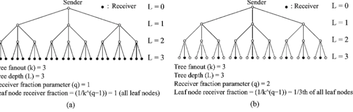
Fig. 7. Example ofk-ary tree parameters.
in the above example, the latency, data and control overhead, and exposure are respectively 0.79, 1.25, 1.625, and 0. If we use vanilla LMS (see Fig. 3), the latency, data, and control overhead are respectively 0.63, 1.125, and 1.625. However, the average re-ceiver exposure in Fig. 4 for each of the rere-ceivers that receive an extra packet is .
III. ANALYSIS OFRAHANDALH USING -ARYTREES
To gain an initial understanding of the scalability of the ALH and RAH schemes, we conduct some simple analyses on -ary trees. In our analyses, we assume that the root of the tree is the sender, and that a fraction of the leaf nodes are receivers. Thus, a -ary tree of depth has between and receivers. The size of the receiver set is specified by a parameter (where
), such that the fraction of leaf nodes that are receivers is . For example, Fig. 7(a) shows a 3-ary tree with tree depth and (i.e., all leaf nodes are receivers). Fig. 7(b) shows the same tree but with (i.e., rd of the leaf nodes are receivers). In case of ALH we assume that the recovery hierarchy is created such that each parent has children. Given these assumptions, the same parent nodesfor ALH are the repliers for RAH. We assume a single link loss and compute for both schemes the average (per link-loss across all links) for each of the metrics described in Section II-C.
First, we present the analytical results for the control over-head and briefly describe the methodology used to derive them. Then, we present the analytical results for data overhead and for recovery latency. We do not analyze the receiver exposure metric because in this particular scenario it is always zero for both schemes.
A. Control Overhead Analysis
To analyze the average control overhead, we need to compute the following: 1) if there is a packet loss on a link, the control overhead (in term of number of hops) to recover the packet; 2) the size of the subtree below (and including) the link where the loss has occurred, so we can compute the relative control overhead for that lossy link; and 3) the total number of links that are lossy (one at a time).
In the particular scenario of a -ary tree with the receivers chosen among the leaf nodes, the RAH and ALH control over-head by definition is same. The reason is because exactly same nodes that have parent-child relation in ALH, have
replier-re-questor node relation in RAH; hence, the control packets in both schemes are sent over exactly same paths. Therefore, the results below apply for both ALH and RAH.
First, we can make the following observation. If we consider the impact of a single loss on a link at some level of the tree, the total contribution to control overhead from independent single link losses on all links on that level does not depend on the particular tree level. This can be illustrated by the 3-ary tree example shown in Fig. 7(b) which has only 1/3 of all leaf nodes being receivers. If we assume that the losses are at the leaf links, the control overhead sum in number of hops for the first three leftmost receivers to reach a replier or a parent would be
. The control overhead sum for the three receivers in the middle is same, but for the three rightmost receivers the control overhead sum is . Therefore, the sum among all nine receivers is
. If we consider the control overhead when the lossy links are right above the nodes, then the total sum is same, except that the subtree size below each lossy link is two instead of one. Similarly, if we consider the case when the losses are at the topmost three links, the control overhead sum is same, except that each time there is a loss on a link, it will affect three receivers instead of one.
The control overhead sum can be computed by considering iteratively the size of the corresponding subtrees. Hence, if the lossy links are at some level of the tree, the control overhead sum is
(1) where is the tree fanout, is the tree depth, and defines the fraction of leaf nodes that are receivers according to the formula . Note that this sum does not depend on the particular level of the lossy links.
To compute the relative control overhead, we need to compute the tree size below a lossy link. If the lossy links are located in level ( for leaf links), the subtree size depends on the value of and can be expressed by the following two equations: (2)
(3) Hence, the relative control overhead sum across all links is
(4) Finally, to compute as defined in Section II-C, we need to divide the above sum by the total number of lossy links (i.e., the links with downstream receivers):
(5) Based on the above expressions, we can plot the results for dif-ferent trees. Fig. 8 shows the control overhead for both RAH and ALH for binary and 4-ary trees of depth when we vary the fraction of the receiver nodes. The results for trees with larger depth and fanout were similar.
B. Data Overhead Analysis
Unlike the control overhead, there is difference between the data overhead for RAH and ALH, which comes from the different data retransmission method. To compute the data overhead, we can use a method similar to the computation of the control overhead described in Section III-A. Because the methodology is similar to that in the previous section, we omit the details of the derivation (see [14] for details).
Similar to the results for the control overhead, we use the de-rived equations to plot the results for binary and 4-ary trees of depth (see Fig. 9). First, we can notice that there is al-most no difference between the RAH and ALH data overhead. Further, the results are very similar to the control overhead (see Fig. 8). The reason for the small difference between RAH and ALH is as follows. In this particular setup, the advantage of using RAH comes from the data retransmission method: in some cases a single RAH replier uses multicast to retransmit the data to all receivers within a subtree, while in case of ALH the re-transmission would be a sequence of multicast rere-transmissions, one at each level of the hierarchy. However, only when the lossy link is close to the root of the tree, the number of sequential re-transmissions can be on the order of , and even then the extra data overhead would be relatively small. Therefore, on average the RAH advantage compared to ALH is very small.
Notice, by comparing Figs. 8 and 9, that the difference be-tween the data data and control overhead is very small. The reason for that is because in most cases only a single receiver
Fig. 8. Average control overhead (same for RAH and ALH).
Fig. 9. RAH and ALH: average data overhead.
will experience losses and therefore, by definition the data and control overhead would be same.
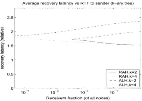
C. Data Recovery Latency Analysis
The data recovery latency computation method is slightly dif-ferent from the computation of the data and control overhead. First, we compute the sum of the latencies when the lossy links are at some level of the tree. After that, we sum the laten-cies for all . Finally, we normalize the result by the round-trip time to the sender, and then we average across all links. For brevity we omit the computation (see [14] for details). The results for the data recovery latency for binary and 4-ary trees of depth are in Fig. 10. We see that the ALH data recovery latency is higher than the RAH latency, and the dif-ference increases logarithmically with the number of receivers. On the other hand, the difference does not appear to be very large, and in the worst case the ALH latency is 50% larger than the RAH latency (for ). Even when we increased the tree depth to , the ALH was within the order of two of the RAH latency. The reason that, unlike the data overhead, the dif-ference between the RAH and ALH data recovery latency is notable is that when we normalize the latency by the RTT to the sender, the result is much more sensitive to a single extra link-hop the retransmitted data may travel. On the other hand, the impact of that single extra link-hop when we compute the data overhead is much smaller when we normalize by the af-fected subtree size.
Fig. 10. RAH and ALH: average data recovery latency.
IV. SIMULATIONRESULTS
The analytical results we presented in Section III apply only given the assumptions we have about the topology and the receivers setup, and may not be true when we have different topologies or receiver placement. Some of the questions we want to answer through numerical simulations are the following.
• How do RAH and ALH perform with real-world router-level topology and how do they compare to each other? • How other topologies may impact the results?
• How the receiver placement may impact the results? • What is the impact of the hierarchy creation parameter for
the ALH scheme?
• What would be the performance penalty for ALH if we did not use any heuristic to create the data recovery topology (i.e., if the hierarchy was randomly created)?
First, we describe our simulation setup, and then we present and discuss the results.
A. Simulation Setup
In most of the simulations we use a router-level Internet-core topology of 54 533 nodes [10]. To investigate the sensitivity of our results to the underlying topology, we use several other topologies: AS-level map [15], [11], Mbone [13], random graph, mesh, and tree. Some of the characteristics of those topologies are summarized in Table I.
We assume a single-source multicast distribution tree with the source at the root of the tree.
To investigate the sensitivity of the results to receiver loca-tion, we look into several receiver placement models. Our goal is not to explore all possible receiver placements, but to con-sider the extreme cases, along with the random case. This helps us understand the range of expected performance.
The first model we look into is therandom client placement, where the receiver nodes are selected at random with uniform probability.
We examine extreme receiver placement models as defined in [16], namely,extreme affinityandextreme disaffinity. The ex-treme affinity model places the receivers as close as possible to each other; the extreme disaffinity model places the receivers as far as possible from each other. The particular algorithm we use to place a number of receivers on a graph according to
TABLE I
METRICS OFUSEDTOPOLOGIES
the affinity/disaffinity model is described in [17]. Below is a brief summary of that algorithm. The first receiver is selected at random among all nodes. Then, we assign to each node that is not selected yet the probability , where is the closest distance between node and a node that is already selected as a receiver, is calculated such that , and is the parameter that defines the degree of affinity or dis-affinity. After a node is chosen to be a receiver, the probabilities of the remaining nodes are recomputed and the process is re-peated until the desired number of receivers is selected. Similar to [17], in our experiments we use and for extreme affinity and disaffinity, respectively.
We look into yet another extreme receiver placement:extreme clustering. This placement can be considered a hybrid between extreme affinity and extreme disaffinity. With this placement, receivers are “grouped” into a number ofclusters, such that the receivers that belong to the same cluster are as close as pos-sible to each other (i.e., extreme affinity placement). Then, all clusters are placed as far as possible from each other (i.e., ex-treme disaffinity placement). A two-step version of the exex-treme affinity/extreme disaffinity algorithm described above can be used to create the extreme clustering as well. In the first step, we place receivers with extreme disaffinity with parameter- , where is the total number of receivers. Each of those clients is considered as a center of a cluster of size receivers. In the second step, we add receivers to each cluster by using the extreme affinity algorithm with parameter .
The number of the receivers varies as a fraction of topology size between 0.0001 and 0.2 (i.e., 0.01% and 20% of all nodes).4
The default hierarchy creation parameter for the ALH scheme is 0.1, i.e., on average each parent has nine children . Further, to prevent an extremely uneven distribution of the chil-dren among the parents, the maximum number of chilchil-dren a parent may have at each level is set to , where is the hierarchy creation parameter. For ALH, we evaluate two hierarchy creation approaches. The first approach, which we callALH-heuristic, uses the inter-receiver distance heuristic described in Section II-A. The second approach, ALH-random, selects at random the set of parents at each level of the hierarchy, and then each child chooses randomly its parent. The results for ALH-random give us the worst-case ALH per-formance, when we do not have a good mechanism to create the recovery hierarchy. For each set of parameters we perform 50 simulations with a different set of receivers.5 Our results are 4For the smaller topologies the smallest fraction was 0.0002 or 0.001,
de-pending on the topology size.
5We did some experiments with a larger number of receiver sets but in all
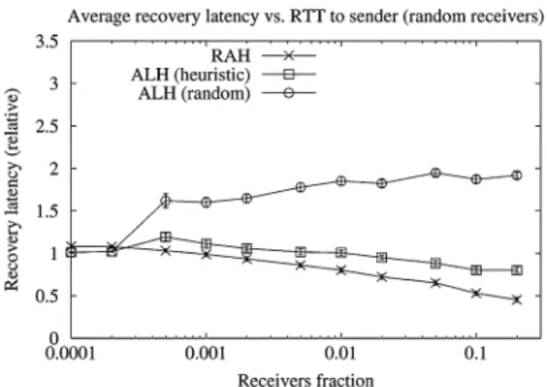
Fig. 11. RAH and ALH (Internet core): average data recovery latency.
averaged across all simulations, and we include the 95% confi-dence interval (even though in most cases this interval is very small to be noticed).
For each scheme we measure the data recovery latency, expo-sure, data overhead, and control overhead for a single link loss. For simplicity, we assume that all links have the same prop-agation latency, and that sending a single packet over any of the links creates the same overhead to the network. The mea-sured results are averaged across all links that are a part of the multicast tree (in Section IV-C4 we consider an alternative link loss model). The metrics are computed using the expressions in Section II-C.
As we mentioned in Section I, we are not interested in inves-tigating the particular protocols in details, but only in the under-lying schemes instead. For this reason we did not include in the basic schemes various protocol enhancements such as multiple LMS router state for routers with large fanout [2] that can help to reduce the control overhead.
In Section IV-B, we present the results for the Internet core topology with random receiver placement. In Section IV-C we present the sensitivity results: ALH hierarchy organization sen-sitivity (Section IV-C1), topology sensen-sitivity (Section IV-C2), receiver placement sensitivity (Section IV-C3), and link loss model sensitivity (Section IV-C4).
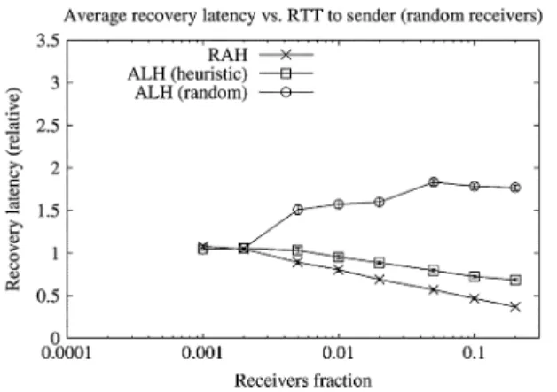
B. RAH and ALH Simulation Results
Fig. 11 shows the data recovery latency for RAH and ALH for the Internet core topology and random receiver placement. The results for RAH do match qualitatively our analytical results. The reason that the RAH latency decreases when the number of receivers increases can be explained by the following observa-tion. A larger number of receivers increases the probability that there is a topologically close replier that has received the data, and therefore, the recovery latency will be shorter. Surprisingly, the ALH-heuristic results were very similar to the RAH results but did not match our analytical results. This can be explained by the fact that in the -ary trees there is strict enforcement on the recovery hierarchy construction (i.e., a parent can only be a leaf node), while in real-world topologies our heuristic will quite likely choose for each child its parent node to be in the proximity of the shortest path from the child to the root. It is quite likely that such node will be chosen as a replier in RAH, and therefore,
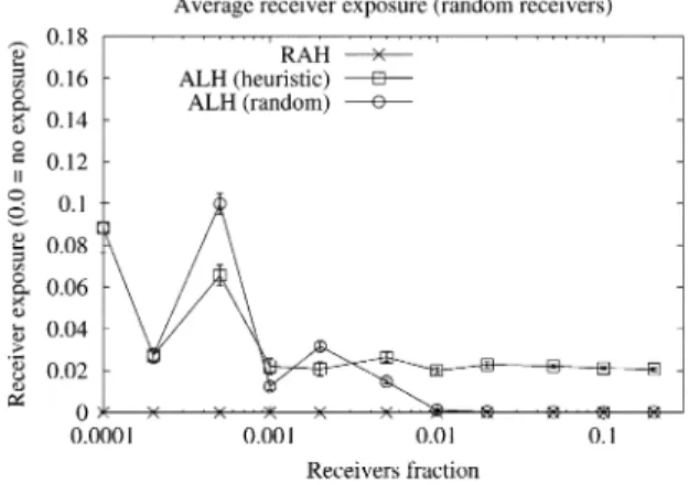
Fig. 12. RAH and ALH (Internet core): average receiver exposure.
the results for both schemes are similar. On the other hand, it is less likely that in ALH-random the parent will be on the shortest path. Hence, when the number of receivers increase, the number of levels in the data recovery hierarchy which do not follow the shortest path between the sender and each receiver will increase as well, and therefore, the receiver latency will be longer.
Fig. 12 presents the results for the receiver exposure. The RAH exposure is always zero by definition (true for a single link loss, but may not always be true if there are multiple link losses). The results for both ALH-heuristic and ALH-random are rea-sonably low. Surprisingly, ALH-heuristic performed worse than the ALH-random. The reason is that in ALH we can have ex-posure only if the parent uses multicast to send the data to its children. In our simulations the parent would use multicast only if at least 50% of the children did not receive the data. With ALH-heuristic it is more likely that children that share same parent are topologically close to each other, and therefore, if any of them did not receive the data, there is larger probability that at least 50% of its siblings did not receive it either (i.e., larger probability that the parent will use multicast to retransmit the data).
Figs. 13 and 14 show the results for data and control overhead, respectively. Here again the results for RAH and ALH-heuristic are very similar. However, while the RAH results match the an-alytical results, it is difficult to say the same thing for the ALH. Similar to the latency, the ALH-random results show that the overhead increases for a larger number of receivers, an artifact from the increased average depth of the data recovery tree.
We should note that for all simulations the data and the control overhead seemed to be almost identical. On closer examination, the RAH control overhead was approximately 5%–10% higher than the data overhead. We can explain the reason for this small difference by the fact that there is extra control traffic only over the path between a router-turning point and its replier, a path that by definition is as short as possible for that router, therefore, the control overhead is minimized. Indeed, this overhead can be up to , but in most cases it does not have a significant impact. For ALH the control overhead was even closer to the data overhead. The reason for this can be explained by the observation that the data overhead can be smaller only if the parent used multicast, but then the gain in some parts in the network may be reduced by the exposure in other parts.
Fig. 13. RAH and ALH (Internet core): average data overhead.
Fig. 14. RAH and ALH (Internet core): average control overhead.
C. Simulation Results Sensitivity
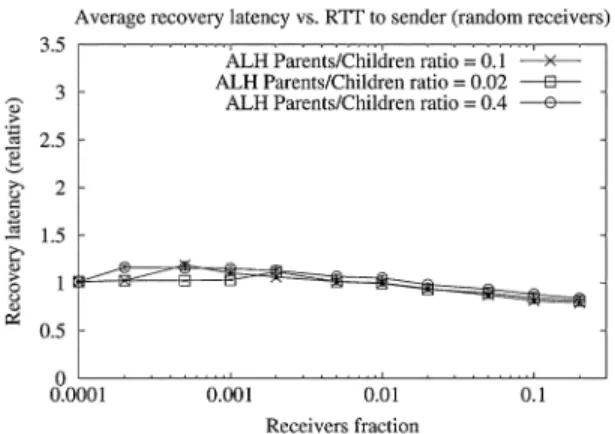
1) ALH Hierarchy Organization Sensitivity: Fig. 15 shows the latency results for three different values of the hierarchy cre-ation parameter : 0.02, 0.1, and 0.4.6 Interestingly, this
parameter had almost no impact on the latency (only for a very large number of receivers the results for larger parameter value were slightly better). We believe that the reason for this is as fol-lows. When the number of receivers is large, the recovery tree depth is large too. However, when the number of receivers in-creases, there is a higher probability that a parent will be on the shortest path between a child and the root (or at least close to the shortest path). Then, if all of the parents are on the shortest path, there is no extra latency regardless of the number of inter-mediate hops to the root.
The data and control overhead results (Figs. 16 and 17) do show however, that the overhead is more sensitive to the number of parents a child has to choose from. The higher sensitivity of the data and control overhead compared to the latency sensi-tivity can be explained by the fact that there is a large number of leaf links (i.e., when the size of the subtree that lost the data is 1), and in all those cases the overhead is much more sensitive to the distance to the parent that eventually has the data. On the contrary, the number of receivers that have very small round-trip time (the basic for comparing the latency), and therefore, the distance to their parents may have a larger impact on the result, is much smaller.
6Note that for a very small number of receivers and a small parameter value
the results are identical simply because the result is always a two-level hierarchy: the sender is the root and all receivers are its children.
Fig. 15. ALH: data recovery latency sensitivity to hierarchy organization.
Fig. 16. ALH: data overhead sensitivity to hierarchy organization.
Fig. 17. ALH: control overhead sensitivity to hierarchy organization.
From Fig. 18 we can see that exposure increases when the number of potential parents is larger. The reason for the increase is because of the increased locality among all siblings, and there-fore, there is a larger probability the parent would use multicast to recover the data.
2) Network Topology Sensitivity: Figs. 19–23 show the av-erage latency for AS, Mbone, random graph, mesh, and tree re-spectively. All results are with random receiver placement. If we compare them with the Internet-core (Fig. 11), we can see that the results are similar. The only notable exception is the mesh where the difference between RAH and ALH-heuristic is much larger for a large number of receivers. We believe the reason for this is because the multicast distribution tree is composed of long, skinny branches, an artifact of the particular routing in the
Fig. 18. ALH: receiver exposure sensitivity to hierarchy organization.
Fig. 19. RAH and ALH topology sensitivity (AS): average data recovery latency.
Fig. 20. RAH and ALH topology sensitivity (Mbone): average data recovery latency.
mesh. Therefore, even small inaccuracy in the parent selection heuristic may have a large penalty in inefficiency.
The results for the data and control overhead were qualita-tively similar to the Internet core results, with the notable excep-tion of mesh for which again ALH-heuristic performed notably worse compared to RAH for large number of receivers. The re-sults for the receiver exposure for all topologies were qualita-tively similar to the Internet core results.
3) Receiver Placement Sensitivity: Figs. 24–26 show the data overhead results for the Internet core topology with extreme affinity, extreme disaffinity, and extreme clustering
Fig. 21. RAH and ALH topology sensitivity (Random graph): average data recovery latency.
Fig. 22. RAH and ALH topology sensitivity (Mesh): average data recovery latency.
Fig. 23. RAH and ALH topology sensitivity (Tree): average data recovery latency.
receiver placement respectively. If we compare them with the random receiver placement (Fig. 13), we can see that the extreme affinity and extreme disaffinity results are qualitatively similar to the random receiver placement results. Only in case of extreme clustering placement, the difference between RAH and ALH-heuristic can be on the order of four times and more. The results for the control overhead were similar to the data overhead results. The results for the data recovery latency and receiver exposure were similar across all receiver placement models.
Fig. 24. RAH and ALH (Internet core, receiver affinity): average data overhead.
Fig. 25. RAH and ALH (Internet core, receiver disaffinity): average data overhead.
Fig. 26. RAH and ALH (Internet core, receiver clustering): average data overhead.
For other topologies, the impact of the receiver placement was similar, though the difference between extreme clustering and random placement was smaller.
4) Link Loss Model Sensitivity: Our evaluations have so far assumed that each link is equally likely to experience packet loss. Unfortunately, there is no widely accepted “realistic” link loss model that we could have used. Indeed, what little literature there exists on the subject is divided—Yajniket al.[18] suggest that the losses at the network occur on the links that are closer to the receivers, but the results from a later study [19] contradict this.
Fig. 27. RAH and ALH (Internet core, lossy inter-AS links): average data recovery latency.
Fig. 28. RAH and ALH (Internet core, lossy inter-AS links): average data overhead.
Just to verify that our results are not incidental to the choice of link loss model, we reran some of the simulations by assuming that the inter-AS links (i.e., the links between border routers) have a loss probability twice that of the intra-AS links. This choice is plausibly realistic, since it is currently assumed that inter-ISP links are more congested than intra-ISP links. Figs. 27 and 28 show the data recovery latency and data overhead results for the Internet core topology with random receiver placement when the loss probability of inter-AS links (i.e., the links be-tween border routers) is twice the loss probability of inner-AS links. We can see that the results are almost identical with the results when all links have same loss probability (Figs. 11 and 13, respectively). The results for other metrics and other receiver placement models were very similar.
The results from our simulations did show that ALH schemes with a good hierarchy organization can perform within a con-stant factor of RAH schemes. Further, the ALH performance was not affected by the levels in the hierarchy, but primarily by the parent selection at each level of the hierarchy. The results were similar for all topologies (with the exception of the mesh topology in some cases).
V. RELATEDWORK
Previous comparisons between assisted and nonassisted schemes [2] were limited in scope compared to our current work. For example, network overhead was not considered, and the topologies used were much smaller (approximately 200
nodes) generated topologies, where here we use large (over 50K nodes) real network topologies. Moreover, in this work we have added analysis to complement our results.
We now briefly describe reliable multicast schemes and dis-cuss whether they can be classified as ALH or RAH schemes. Our list is not exhaustive. We begin with the nonassisted schemes first.
SRM [1] employs two global mechanisms to limit the number of messages generated, namely duplicate suppression and back-off timers. In SRM, recovery messages (requests and replies) are multicast to the entire group; receivers listen for re-covery messages from other receivers before sending their own, and suppress duplicates. Thus, SRM creates a virtual hierarchy on the fly every time there is loss in the group. However, lack of scoping means that requests and retransmissions generated by SRM will reach the entire group. Local recovery methods have been proposed for SRM [20], which bring SRM closer to our ALH scheme.
RMTP [3] is a typical example of a static hierarchical scheme which closely resembles our generic ALH scheme. The group is manually configured into designated receivers (DRs) and their children. DRs and their children form local groups. The source multicasts data to all receivers on the global group, but only the DRs return acknowledgments. Children unicast acknowl-edgments to their DRs, which schedule retransmissions using either unicast or local multicast depending on how many re-quests a DR has received. The log-based receiver-reliable mul-ticast (LBRRM) [4] is another example of a static hierarchical scheme.
The tree-based multicast transport protocol (TMTP) [8] is an-other example of an ALH scheme, but uses a dynamic hierarchy. In TMTP, new members discover parents using an expanding ring search. Each endpoint maintains the hop distance to its parent, and each parent maintains the hop distance to its farthest child. These values are used to set the TTL field on requests and replies to limit their scope. LGMP [21] is another hierar-chical, subgroup-based protocol, where receivers dynamically organize themselves into subgroups by selecting a Group Con-troller to coordinate local retransmissions and process feedback messages. TRAM [5] is another dynamic tree-based protocol designed to support bulk data transfer. The tree formation and maintenance algorithms borrow from other schemes like TMTP, but TRAM has a richer tree management framework. TRAM supports member repair and monitoring, pruning of unsuitable members, and aggregation and propagation of protocol related information.
Moving to router-assisted schemes, addressable internet mul-ticast (AIM) [7] is a scheme that uses forwarding services that require routers to assign per-multicast group labels to all routers participating in that group. AIM uses these labels to send a request toward the source which get redirected to the nearest upstream member. If data is available, the NACK receiver re-sponds with a retransmission which is also forwarded according to the router labels. Active error recovery (AER) [22] is another scheme that is very similar to our RAH scheme. In AER, each router that has a repair server attached periodically announces its existence to the downstream routers and receivers, and serves as a retransmitter of the lost data on the subtree below it, or collects and send NACKs upstream. OTERS [6], uses a
mod-ified version of the mtrace [23] utility to build the hierarchy by incrementally identifying sub-roots using back-tracing. For each subroot, OTERS selects a parent. Unlike our RAH scheme, OTERS assumes the responsibility of discovering the topology and keeping track of changes in the structure of the underlying multicast group. Similar to OTERS, Tracer [24] also uses mtrace to allow each receiver to discover its path to the source. Once the path is discovered, receivers advertise their paths to near-by receivers using expanding ring search. Once receivers discover nearby receivers, they use the data from the traces and their loss rate to select parents.
Finally, PGM [9], unlike the schemes described earlier, peeks into transport headers to filter messages. NACKs create state at the routers which is used to suppress duplicate NACKs and guide retransmissions to receivers that requested them. PGM creates a hierarchy rooted at the source, but provision is made for suitable receivers to act as designated local retransmitters (DLRs), if desired.
VI. CONCLUSION
In this paper, we took a first cut at understanding the larger design question: Do router-assisted schemes really perform better at error recovery than application-level hierarchies? Our expectation was that the RAH schemes would significantly outperform the ALH schemes, and our original intention was to demonstrate that. To our surprise, we found that even a relatively simple ALH scheme can perform reasonably well compared to RAH schemes. Further, the results were relatively insensitive across a number of factors: group size, depth of the recovery hierarchy, underlying network topology, receiver placement, and link loss model. In addition, although analysis on regular trees predicted a logarithmically increasing average latency for ALH, that trend disappeared in our simulations using irregular trees on real-world topologies.
One possible explanation for our findings is the congruence, in real and irregular networks, between a well-constructed application-level hierarchy and a router-assisted hierarchy. In this scenario, then, the performance differences arise entirely from the retransmission mechanism employed (directed sub-castvis-a-visunicast). But, in a near-optimal application-level hierarchy, the distance between parent and child is minimized, and the impact of the retransmission mechanism is small. The difference between the two schemes is significant only when losses occur near the root, and the number of levels in the hierarchy is large.
From the surprising finding that the performance difference between RAH and ALH was smaller than we had expected, it is probably too speculative to conclude that application-level hier-archies are more viable than router-assisted hierhier-archies for loss recovery. Our evaluations do not model the complexity and cost of hierarchy construction, particularly in the face of dynamics. They do not also consider that router-assist greatly simplifies application development.
ACKNOWLEDGMENT
The authors would like to thank H. Tangmunarunkit and the anonymous reviewers for their valuable comments.
REFERENCES
[1] S. Floyd, V. Jacobson, C.-G. Liu, S. McCanne, and L. Zhang, “A reliable multicast framework for light-weight sessions and application level framing,” IEEE/ACM Trans. Networking, vol. 5, pp. 784–803, Dec. 1997.
[2] C. Papadopoulos, G. Parulkar, and G. Varghese, “An error control scheme for large-scale multicast applications,” in Proc. IEEE IN-FOCOM, San Francisco, CA, Mar. 1998, pp. 1188–1196.
[3] J. Lin and S. Paul, “RMTP: A reliable multicast transport protocol,” in
Proc. IEEE INFOCOM, San Francisco, CA, Mar. 1996, pp. 1414–1424. [4] H. Holbrook, S. Singhal, and D. Cheriton, “Log-based receiver-reli-able multicast for distributed interactive simulation,” inProc. ACM SIG-COMM, Cambridge, MA, Aug. 1995, pp. 328–341.
[5] D. Chiu, S. Hurst, M. Kadansky, and J. Wesley, “TRAM: A tree-based reliable multicast protocol,” Sun Microsystems, Sun Tech. Rep. SML TR-98-66, July 1998.
[6] D. Li and D. R. Cheriton, “OTERS (On-tree efficient recovery using subcasting): A reliable multicast protocol,” inProc. 6th IEEE Int. Conf. Network Protocols (ICNP’98), Oct. 1998, pp. 237–245.
[7] B. Levine and J. J. Garcia-Luna-Aceves, “Improving Internet multicast with routing labels,” inProc. 5th IEEE Int. Conf. Network Protocols (ICNP’97), Atlanta, GA, Oct. 1997, pp. 241–250.
[8] R. Yavatkar, J. Griffoen, and M. Sudan, “A reliable dissemination pro-tocol for interactive collaborative applications,” inProc. 3rd Int. Conf. Multimedia, San Francisco, CA, Nov. 1995, pp. 333–344.
[9] T. Speakman, J. Crowcroft, J. Gemmell, D. Farinacci, S. Lin, D. Leshchiner, M. Luby, T. L. Montgomery, L. Rizzo, A. Tweedly, N. Bhaskar, R. Edmonstone, R. Sumanasekera, and L. Vicisano, “PGM reliable transport protocol specification,” IETF, RFC 3208, Dec. 2001. [10] R. Govindan and H. Tangmunarunkit, “Heuristics for Internet map
dis-covery,” inProc. IEEE INFOCOM, Israel, Mar. 2000, pp. 1371–1380. [11] U. D. S. Center. The NLANR Project. [Online]. Available: http://moat.
nlanr.net/Routing/rawdata/
[12] M. R. Macedonia and D. P. Brutzman, “MBone provides audio and video across the Internet,”IEEE Computer, vol. 27, pp. 30–36, Apr. 1994. [13] USC/ISI. The SCAN Project. [Online]. Available: http://www.isi.edu/
scan/
[14] P. Radoslavov, “The relationship between topology and protocol perfor-mance: Case studies,” Ph.D. dissertation, Univ. Southern California, Los Angeles, 2001.
[15] University of Oregon Route Views Project [Online]. Available: http://www.antc.uoregon.edu/route-views/
[16] G. Phillips, S. Shenker, and H. Tangmunarunkit, “Scaling of multicast trees: Comments on the Chuang-Sirbu scaling law,” inProc. ACM SIG-COMM, Cambridge, MA, Aug. 1999, pp. 41–51.
[17] T. Wong and R. Katz, “An analysis of multicast forwarding state scal-ability,” inProc. 8th IEEE Int. Conf. Network Protocols (ICNP 2000), Osaka, Japan, Nov. 2000, pp. 105–115.
[18] M. Yajnik, J. Kurose, and D. Towsley, “Packet loss correlation in the MBone multicast network experimental measurements and Markov chain models,” Univ. Massachusetts, Tech. Rep. UM-CS-1995-115, 1995.
[19] M. Handley, “An examination of MBone performance,” USC/Informa-tion Sciences Inst., Los Angeles, Tech. Rep. ISI/RR-97-450, Jan. 1997. [20] C.-G. Liu, D. Estrin, S. Shenker, and L. Zhang, “Local error recovery in SRM: Comparison of two approaches,” Dept. Comput. Sci., Univ. Southern California, Los Angeles, Tech. Rep. 99-648, Jan. 1997. [21] M. Hofmann, “A generic concept for large-scale multicast,” in
Proceed-ings of the 1996 International Zurich Seminar on Digital Communica-tions, B. Plattner, Ed. Zurich, Switzerland: Springer, Feb. 1996, vol. LNCS 1044, pp. 95–106.
[22] S. K. Kasera, S. Bhattacharyya, M. Keaton, D. Kiwior, J. Kurose, D. Towsley, and S. Zabele, “Scalable fair reliable multicast using active services,”IEEE Network—Special Issue on Multicast, vol. 14, Jan./Feb. 2000.
[23] S. Casner and A. Thyagarajan, “mtrace(8): Tool to print multicast path from a source to a receiver,” UNIX manual command.
[24] B. N. Levine, S. Paul, and J. J. Garcia-Luna-Aceves, “Organizing multi-cast receivers deterministically according to packet-loss correlation,” in
Proc. 6th ACM Int. Conf. Multimedia, Sept. 1998, pp. 201–210.
Pavlin Radoslavovreceived the Ph.D. degree from the University of Southern California, Los Angeles.
He is a Postdoc at the International Computer Sci-ence Institute, Berkeley, CA, where he works on the XORP open-source router project. His research inter-ests include Internet routing and multicast.
Christos Papadopoulos(M’92) received the Ph.D. degree from Washington University, St. Louis, MO, in 1999.
He is currently an Assistant Professor at the Uni-versity of Southern California (USC), Los Angeles, where he does research on network security and mul-timedia communications. He is also affiliated with the Information Sciences Institute (ISI) and the In-tegrated Media Systems Center (IMSC) at USC.
Dr. Papadopoulos received the National Science Foundation Career Award in 2002. He has been a member of the Association for Computing Machinery since 1999.
Ramesh Govindanreceived the B.Tech. degree from the Indian Institute of Technology, Madras, India, and the M.S. and Ph.D. degrees from the University of California at Berkeley.
He is an Associate Professor in the Department of Computer Science at the University of Southern California, Los Angeles. His research interests include Internet routing and topology, and wireless sensor networks.
Dr. Govindan is a member of the Association for Computing Machinery.
Deborah Estrin(S’78-M’80-SM’95–F’04) received the Ph.D. degree in computer science from the Mass-achusetts Institute of Technology (MIT), Cambridge, in 1985.
She is a Professor of computer science at the University of California at Los Angeles (UCLA) and Director of the Center for Embedded Networked Sensing (CENS), a newly awarded National Science Foundation Science and Technology Center. She was on the faculty of the Department of Computer Science at the University of Southern California (USC), Los Angeles, from 1986 through mid-2000. She has been instrumental in defining the national research agenda for wireless sensor networks, first chairing a 1998 DARPA ISAT study and then a 2001 NRC study. Her research group develops algorithms and systems to support rapidly deployable and robustly operating networks of thousands of physically embedded devices.
Dr. Estrin received the National Science Foundation Presidential Young In-vestigator Award for her research in network interconnection and security in 1987 at USC. She has served on numerous program committees and editorial boards, including the ACM SIGCOMM, Mobicom, SOSP, and the IEEE/ACM TRANSACTIONS ONNETWORKING. She is a Fellow of the Association for Com-puting Machinery and of the American Association for the Advancement of Science.