Technical Review of Wireless Facility
Application by Varsity Wireless at 724
Route 6, Wellfleet, Massachusetts
August 4, 2015
Introduction
Wireless tower developer Varsity Wireless Investors, LLC (“Varsity”) has been referred to the Cape Cod Commission (the “Commission”) for the review of a Development of Regional Impact (“DRI”) in its application for a 90 foot monopole wireless tower at 724 Route 6 in Wellfleet. Isotrope was engaged by the Commission to review the application for the proposed facility. The Commission’s Regional Policy Plan (“RPP”) defines certain wireless tower developments as DRIs, and refers to the Commission’s Technical Bulletin 97-001 Guidelines for DRI Review of Wireless Communication Towers currently revised to 2010 (“Technical Bulletin”). This report evaluates the application under the terms of the RPP and the Technical Bulletin and focuses on those aspects of wireless facility development unique to wireless facilities. The Commission is well equipped to review the customary environmental factors in this matter that are typical of new developments, such as vehicular traffic or hydrological impacts.
Isotrope has reviewed relevant application materials including, without limitation, the Application Narrative and Exhibits relating to radio frequency coverage, radio frequency exposure, noise, site plans, FCC licenses, and FAA Determination of No Hazard.
Development of Regional Impact
The proposed tower is a wireless communications facility greater than 35 feet in height above ground, and is not proposed as a concealed antenna monopole (which has a DRI threshold of 80 feet). Goal LU2.2 of the RPP states:
Co-location of Telecommunication Facilities: New wireless telecommunications facilities shall be required to demonstrate the commitment of two or more co-locators into the design of the facility. Additional guidance on the location and design of wireless facilities can be found in Guidelines for DRI Review of Wireless Communication Towers, Technical Bulletin 97-001, as amended.
that more than one wireless carrier has established and funded a search ring in the same general area. Presently, new facility development is running at a relatively slow pace in the USA, which means it may be a while before another carrier decides it is time to develop a new facility in the subject area. Nevertheless, Varsity provides for a total of five potential carrier spaces on the proposed tower. The fifth and lowest carrier in a fully built-out situation would have antennas positioned in the 40-50 foot aperture. Tree canopy height is indicated on the plans as 30 to 40 feet. It is typical to make tower space available above the surrounding treetops.
Verizon Wireless is a well-known provider of personal wireless services in Barnstable County. With the application materials Exhibit 15 contains a set of pages of license information from the FCC website. Among the license sheets provided, two are incorrectly for areas that do not include Barnstable County (KNLH242, PCS and KNKA201, Cellular). In addition, four licenses held in Barnstable County are not included in Exhibit 15. The table below contains all six Verizon licenses pertinent to Barnstable County.
# Common Name Radio Service Frequency Band (MHz) Market Call Sign/ Lease ID 1 VerizonWireless 700 MHz 746776 - 787- 757 REA001 - Northeast WQJQ689
2 VerizonWireless AWS - 1 1720 - 17302120 - 2130
BEA003 -
Boston- Worcester-Lawrence-Lowe
WQGA900
3 VerizonWireless AWS - 1 1710 - 17202110 - 2120 CMA471 - Massachusetts2 - Barnstable WQGB350
4 Verizon Wireless Broadband PCS 1890 - 1895 1970 - 1975 BTA201 - Hyannis, MA KNLG356 5 Verizon Wireless Broadband PCS 1885 - 1890 1965 - 1970 BTA201 - Hyannis, MA KNLH253
6 VerizonWireless Cellular
835 - 845 846.5 - 849 880 - 890 891.5 - 894 CMA471 - Massachusetts 2 - Barnstable KNKN826
Goal LU2.2 of the RPP also refers to the Technical Bulletin, which is addressed in a section further below.
Goal LU2.4 states, “Access to Emergency Responders: The construction of new wireless telecommunication facilities should provide access to emergency responders into the design of the facility.” It is not clear what form of “access” is required. Of course, public safety will have an accessible driveway from the street, as shown on the plans. Access to upper elevations of the tower for fire/rescue purposes is sometimes a concern. The Fire Department can provide its opinion on whether any special apparatus is required to ensure worker safety/rescue capability on the tower. Finally, some municipalities seek privileges to mount public safety radio antennas on cell towers. If this is desired, the Town of Wellfleet can comment on any such needs.
Wireless facilities are specifically excluded from Goals E1Emissions and Energy Useand ED1Low Impact and Compatible Development.
Technical Bulletin
Beginning with Section IV, we step through the Technical Bulletin. Technical Bulletin language is in italics. Some content of the Technical Bulletin has been eliminated to promote brevity. IV. Location
Applicants seeking Development of Regional Impact (DRI) approval for personal wireless service facilities should comply with the following:
A. … The applicant shall have the burden of proving that there are no feasible existing structures upon which to locate.
The application asserts that there are no significant structures are available.
Water Tower
The National Seashore water tower is considered and ruled out for being insufficient. It is located some eight tenths of a mile away (NE), in a position that is rather deep into the National Seashore and remote from the residential and business areas of to the west of Route 6. While it is tempting to agree with the applicant that the water tower is not an effective location, it would be helpful to have a coverage map of the water tower in conjunction with existing coverage to illustrate the point.
Transmission Poles
(wooden) that appear to be about 60 feet tall. It is not uncommon for wireless facilities to arrange to replace one of the pair of transmission poles with one that is 10 to 20 feet taller and install antennas on it.
Figure 1 - Tall Transmission Poles (left) along Rail Trail at Marconi Beach Road (typical)
The transmission poles closest to the proposed site are about 375 feet northeast of the proposed tower site and at similar ground elevation. The transmission poles tend to be spaced at 650 to 800 foot intervals (except special conditions where an intermediate installation is necessary). An optimum location could be selected based on such factors as ground elevation, centrality to a target coverage area, local utilities availability and physical access.
Additional analysis of the foregoing factors would be necessary to verify whether using the transmission pole infrastructure is viable.
Figure 2 - Aerial View of Proposed Site and Nearest Transmission Poles
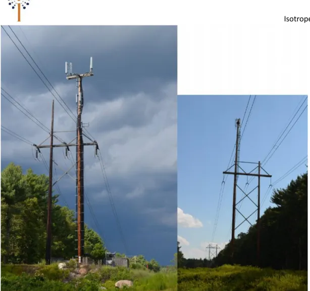
The practice of replacing wooden transmission poles is not uncommon in the region. Below are pictures of two such installations in Medfield. The top antennas on each pole are approximately 90 feet above ground. The pole in the left picture below hosts two wireless carriers. However, neither carrier has installed a full array of antennas (a total of at least 9 and potentially 12). If Verizon were to occupy the same space, there might not be room for a co-locator.
Also note, these transmission line poles and the rail trail appear to fall within the boundary of the National Seashore. We leave it to others to determine whether this limits wireless deployment on the transmission poles in any way.
Figure 3 - Replacement Transmission Poles with Antennas
B. If the applicant demonstrates that it is not feasible to locate on an existing structure, personal wireless service facilities should be designed so as to
be camouflaged to the greatest extent possible, including but not limited to use of compatible building materials and colors, screening, landscaping and placement within trees.
The proposed ground facilities appear to be well isolated from public view. The visibility analysis produced by Caron Associates Design employs appropriate methodology to develop a 3D model and render accurate representations of the proposed tower from various locations. Since the proposed tower is not camouflaged, at those locations where it is visible, the visual clutter of the antenna arrays and mounts is evident. Depending on the context of any particular view this might or might not be palatable to stakeholders.
Concealed Antenna Monopole
First, the concealed antenna monopole design (also called a “unipole,” “slick-stick,” or “flagpole”) is contemplated as a non-DRI if it were up to 80 feet high. The application is for a 90 foot tower. It would be instructive to see whether there is significant reduction in Verizon Wireless performance with an 80 foot tall concealed antenna monopole instead of the 90 foot height proposed.
Bear in mind that there are trade-offs in using a concealed antenna monopole. The array of up to 12 antennas (4 per sector) in the proposal would have to be consolidated in the narrow radius of the tower. Typically, carriers seek two ten-foot apertures in the concealed antenna monopole to accommodate their antennas. The use of a second aperture reduces the co-location capacity of the structure, not only because the initial tenant uses two apertures, but also some other carriers joining the tower might also demand two apertures. In short, converting the proposed tower to a concealed antenna unipole could reduce it from a five-carrier tower to as little as a two-five-carrier tower.
Another potential trade-off results from the limited space within the cowling of the concealed antenna monopole. Carriers are now typically installing the radio electronics on the towers beside their antennas. This allows them to connect by fiber optic cable from the ground equipment to the on-tower radio heads. Heavy coaxial cables are eliminated, and the resulting power losses of the coaxial cables are eliminated, thereby potentially improving coverage.
The next potential trade-off of using a concealed antenna monopole is that half of the antenna array is ten feet lower than the other half. This might result in additional reduction in performance. The applicant could model coverage from a concealed antenna monopole using the foregoing assumptions to provide a performance
comparison with the proposed installation. Consideration could be given to allowing a taller pole in compensation for the sleeker design of the concealed antenna monopole.
Faux Structures
In locations where the visual impact of a tower with typical open-frame antenna arrays is critical, and a concealed antenna monopole is not sufficient (due to reduction in co-location, or other losses of efficiency), other ways of camouflaging towers have been employed. In Hollis, New Hampshire, the town has approved faux fire towers in two different locations, about ten years apart. The first tower is pictured below. Note that from the point of view of the property, this tower looks unrealistically tall, because it is. It is 140 feet tall. However, from the vantage points around this hilly town, it only peeks above the treetops and seems more in proportion. In the present situation, a 90 foot tall fire tower might not look so out of proportion.
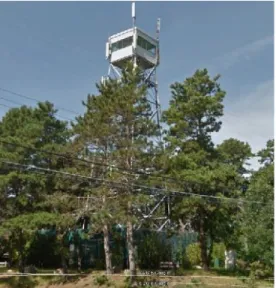
Figure 5A and B - Faux Towers: Fire Lookout, Hollis, NH; Water, Branford, CT
In Branford, Connecticut, in a semi-rural area near the working railroad of a gravel company, a faux water tower was installed. It contains full antenna arrays of several wireless carriers and stands about 110 feet tall.
For comparison, the Wellfleet fire tower is 68 feet tall (without antennas) and very close to Route 6. (below)
Caron Associates Design can provide photosimulations of the concealed antenna monopole, faux fire tower, water tower or other design, if the Applicant is asked and is willing to obtain them.
It is important to note, as we said as far back as the Truro landfill tower application in 2002, carriers have more flexibility to efficiently utilize the open frame antenna array configurations such as are proposed in this matter than when restricted to certain concealment and design specifications. We advise that only when there is a material improvement in visual impact is the benefit of requiring a camouflaged design likely to be worthy of consideration. The extremely limited visibility of the Truro landfill tower enabled it to be approved with open-frame antenna arrays. At other locations on the Cape, more significant visual impact mitigation has been required.
C. The applicant shall submit documentation of the legal right to install and use the proposed facility mount at the time of application for a Development of Regional Impact approval.
We leave this to in-house counsel to verify. Documents have been filed by the applicant. V. Dimensional Requirements
Personal wireless service facilities should comply with the following requirements: A. Height, General. Personal wireless service facilities should be no higher than ten feet above the average height of buildings within 300 feet of the proposed facility. However, the height of a personal wireless service facility should not exceed the height limits of the zoning district in which the facility is proposed to be located, unless the facility is completely camouflaged such as within a flagpole, steeple, chimney, or similar structure.
It appears the height limits in Wellfleet are 28 feet in all districts (§5.4.4 of Wellfleet Zoning Bylaws). While we found no 300 foot radius on the site plans provided with the application, it appears only the two buildings on the parcel are within this radius. Moreover, the district height limit seems to be the controlling height, assuming average height of these buildings is at least 18 feet.
B. Height, Ground-Mounted Facilities. Ground-mounted personal wireless
service facilities (i.e. wireless communication towers) should not project higher than ten feet above the average building height or, if there are no buildings within 300 feet, these facilities should not project higher than ten feet above the average tree canopy height, measured from ground level (AGL). If there are no buildings within 300 feet of the proposed site of the facility, all ground-mounted personal wireless service facilities should be surrounded by dense tree growth to screen views of the facility in all directions. These trees may be existing on the subject property or proposed to be planted as part of the application.
It appears the only buildings within 300 feet are the two on the subject parcel. If this is a material question, the applicant could be instructed to document the answer. If an allowance is made to apply the tree canopy height limit in this subsection, the applicant indicates a 30-40 foot tree canopy height. This is simply stated on the drawing with no supporting documentation. Assuming a 35 foot average canopy height, the height of the tower would be limited to 45 feet above ground. In the context of the proposed facility, these heights are impracticable.
C. Height, Wireless Facility Overlay Districts. If a town has established a
wireless facility overlay district (as designated on the town zoning map) where taller facilities are permitted, personal wireless service facilities of up to 150 feet in height may be allowed. Monopoles are the preferred type of mount for such taller
structures.
We found no such overlay district in the Zoning Bylaws or on the Zoning Map of Wellfleet. D. Setbacks. All personal wireless service facilities and their equipment shelters
should comply with the building setback provisions of the zoning district in which the facility is located. In addition, the following setbacks should be observed: 1. In order to ensure public safety, the minimum distance from the base of any ground-mounted personal wireless service facility to any property line, road, habitable dwelling, business or institutional use, or public recreational area should be the height of the facility/mount, including any antennas or other appurtenances. This setback is considered a "fall zone." The applicant shall provide proof of a legal interest in the fall zone, including but not limited to proof of fee ownership, an easement, or a leasehold sufficient to meet the requirements of this section.
It is becoming more commonplace to exclude consideration of the subject parcel in such matters, as the landowner and the wireless facility owner have entered into a mutually beneficial agreement, and all building, fire and electrical codes remain applicable for safety. With respect to adjacent parcels, the applicant shows a height-plus-ten-feet setback to the property lines, in conformance with the limitation in the Zoning Bylaw §6.18.2.2.
2. In reviewing an application for a personal wireless service facility, the Commission may reduce the required fall zone by as much as 50% of the recommended distance, if it finds that a substantially better design will result from such reduction. In making such a finding, the Commission should consider both the visual and safety impacts of the proposed facility.
Unless the Commission choses to apply the fall zone to the subject property, it appears this section would be not applicable.
VI. Special Regulations. Personal wireless service facilities should comply with the Performance Standards set forth in this section.
A. Design Standards
1. Camouflage. Personal wireless service facilities should be camouflaged or hidden from public view wherever possible by incorporating them into an existing or proposed structure, by using fiberglass to replace building elements, and/or through careful selection of construction materials and/or color. See discussion of camouflage above.
2. Buffers. If personal wireless service facilities are not camouflaged from public viewing areas by existing buildings or structures, they should be surrounded by buffers of dense tree growth and understory vegetation in all directions to create an effective year-round visual buffer. Ground-mounted personal wireless service facilities should provide a vegetated buffer of sufficient height and depth to effectively screen the facility. Trees and vegetation may be existing on the subject property or installed as part of the proposed facility or a combination of both. The Commission will work with the applicant to determine the types and sizes of trees and plant materials and depth of the needed buffer based on site conditions.
3. Color. To the extent that any personal wireless service facility extends above the height of the vegetation immediately surrounding it, it should be painted in a light grey or light blue hue which blends with sky and clouds.
Coordinate with the camouflage discussion above.
4. Equipment Shelters. Equipment shelters for personal wireless service facilities should be designed consistent with one of the following design standards:
a. Equipment shelters should be located in underground vaults; or
b. Equipment shelters should be designed consistent with traditional Cape Cod architectural styles and materials, with a roof pitch of at least 10/12 and wood clapboard or shingle siding; or
c. All ground-mounted personal wireless service facilities should be
surrounded by a security barrier. Equipment shelters should be camouflaged behind an effective year-round landscape buffer, equal to the height of the proposed building, and/or wooden fence. The Commission, in consultation with local officials will determine the style of fencing and/or landscape buffer that is compatible with the neighborhood.
No peaked roof or shingling is proposed for the precast shelter, which will be 10 feet tall behind an opaque fence 8 feet tall. (This may not be critical, but the fence is marked on the plans as “stockade fence” but seems to be shown as another style of privacy fence).
5. Lighting and Signage
a. Personal wireless service facility mounts should be lighted only if required by the Federal Aviation Administration (FAA). Lighting of equipment shelters and any other facilities on the ground should be designed in accordance with Technical Bulletin #95-001, Development of Regional Impact Guidelines for Exterior Lighting.
We comment only on the FAA aspect, and leave the Exterior Lighting review to Commission staff. The Applicant provided an exhibit consisting of an FAA Determination of No Hazard. The coordinates are approximately 95 feet out of place. The ground elevation is approximately 10 feet low. However, the height requested for the Determination is 160 feet above ground. This height is so far above the proposed height that the minor deviations in position and elevation
between the FAA Determination and the proposed site are immaterial. The Determination of No Hazard confirms that no navigation lighting will be required.
b. All signs should comply with the FCC and applicable requirements of the town's sign regulations.
6. Historic Districts Personal wireless service facilities should not be located within an historic district unless they are completely camouflaged.
7. Scenic Landscapes and Vistas
a. Personal wireless service facilities should not be located within open areas that are visible from public roads, recreational areas or residential
development. All ground-mounted personal wireless service facilities which are not camouflaged by existing buildings or structures should be surrounded by a buffer of dense tree growth.
b. Any personal wireless service facility that is located within the viewshed of a scenic vista, scenic landscape or scenic road as designated by a town should not exceed the height of vegetation at the proposed location.
We leave the foregoing sections to others to evaluate. B. Noise Standards
Ground-mounted personal wireless service facilities should not generate noise from equipment and/or wind in excess of 50 db at the property line.
The applicant provided an exhibit containing a professional noise assessment (Exhibit 17 – Environmental Sound Assessment). The assessment relied on field measurements and calculations, performed in the customary manner. The assessment concludes that all noise criteria (Commission, Commonwealth and Town) are satisfied by the project design. The project design includes special muffler, ventilation noise reduction, and noise blocking material on the compound fence.
C. Radiofrequency Radiation (RFR) Standards
All equipment proposed for a personal wireless service facility should be authorized per the FCC Guidelines for Evaluating the Environmental Effects of Radiofrequency Radiation (FCC Guidelines).
The application includes a radio frequency energy exposure analysis (Exhibit 18 – SAI Maximum Permissible Exposure Study). The analysis assumes four wireless carriers are occupying the proposed tower at heights from 147 to 127 feet above ground level. This analysis was apparently performed before the proposed height of the tower was established at 90 feet. The analysis therefore assumes the antennas are farther away from humans than they are now proposed.
There would be an increase in on-ground radio frequency energy exposure potential if the antenna heights were corrected. However, when accounting for the reduced antenna heights, the change in results of the study would not change the conclusion. At the incorrect height, the maximum predicted exposure potential was in fractions of a percent of the applicable limit. For the sake of estimating, if we assume the antenna heights will be half of that which was originally calculated, which they are not, at the most we would expect a quadrupling of the potential exposure levels on the ground. Multiplying the maximum potential exposure by four, we find that this safe-side estimation of exposure increase would still result in a total potential exposure on the ground of less than 1% of the applicable limit.
Based on the radio frequency energy study’s use of conventional prediction methods, as outlined in FCC Office of Engineering and Technology Bulletin 65, and other best practices, and based on the result which is orders of magnitude below the applicable limit, we propose that the error in predicted antenna height is not material. The proposed facility with the 90 foot tower will be fully compliant with the applicable federal and state safety limits by a large margin. (Note that this recommendation is based on approving the present co-applicant, Verizon; In response to the possibility that advance approval could be granted to additional wireless carriers not presently in the application, we discuss further documentation recommendations in Section VII.D. below.)
D. Hazardous Materials Standards
Under the Regional Policy Plan, a wireless facility in a Wellhead Protection District is limited to household quantities of hazardous materials/waste. The Commission may require provisions for full containment of any hazardous materials used on-site, including an enclosed containment area with a sealed floor, designed to contain 110% of the total volume of all hazardous materials used, handled or stored on the site and a prohibition on floor drains. No hazardous waste should be discharged on the site of any personal wireless service facility.
We defer to others on this subject. In general, wireless facilities do not handle large quantities of hazardous materials. Backup batteries used by the industry typically employ gel electrolytes, eliminating concerns of liquid runoff of leaks. Since there is no disposal of materials on site,
batteries are removed from site when they are replaced. The generator is proposed to run off propane instead of diesel fuel. Typically, no other undesirable materials are employed at cell sites. (If fluorescent light use is of concern from a disposal perspective, there are certainly LED substitutions available for any conventional lighting needs.)
VII. Co-location
A. Licensed carriers should share personal wireless service facilities and sites where feasible and appropriate, thereby reducing the number of personal wireless service facilities that are stand-alone facilities. All applicants for a personal wireless service facility should demonstrate a good faith effort to co-locate with other carriers. Such good faith effort includes:
1. A survey of all existing structures that may be feasible sites for co-locating personal wireless service facilities;
2. Contact with all the other licensed carriers for commercial mobile radio services operating in the County; and
3. Sharing information necessary to determine if co-location is feasible under the design configuration most accommodating to co-location.
To the best of our knowledge, existing cell sites are lacking in the subject area. The applicant has identified the closest cell sites and co-applicant Verizon is on them.
B. In the event that co-location is found to be not feasible, a written statement of the reasons for the infeasibility should be submitted to the Commission…
C. If the applicant does intend to co-locate or to permit co-location, the Commission may request drawings and studies which show the ultimate appearance and
operation of the personal wireless service facility at full build-out.
Applicant intends to permit co-location. In addition to the proposed structural capacity of the tower for multiple tenants’ antenna arrays, the applicant also shows hypothetical lease areas within the proposed compound for several additional wireless carriers.
D. If the Commission approves co-location for a personal wireless service facility site, the permit should indicate how many facilities of what type shall be permitted on that site, including the type, size and location of storage cabinets or buildings.
require no further Commission review. Estimates of RFR emissions will be required for all facilities, including proposed and future facilities.
If the current radio frequency exposure assessment is required to prospectively enable future carriers without further review, it might be helpful if the applicant were to provide more detail for the record: have the applicant modify their report to include at least two additional things: 1) Correct antenna heights for the hypothetical carrier positions, and 2) Include detail tables showing the assumptions used for each carrier’s antenna arrays including frequency bands, power levels and antenna models employed to perform the calculations.
<<End of Technical Bulletin excerpts>>
In addition to the foregoing analysis, we provide general comment for the purposes of administrative notice to the Commission regarding federal requirements.
In addition to the Telecommunications Act of 1996 (§704), there are other rules that affect wireless facility siting. In 2009, the FCC adopted a “shot clock” granting a rebuttable time frame of 150 days for an authority to review and act on application for a new cell tower. Section 6409 of the Middle Class Tax Relief and Jobs Creation Act of 2012 addresses facility modifications, which may color the manner in which the proposed facility might be expanded in the future, if approved. The FCC clarified interpretations of the 2012 Act in WIRELESS TELECOMMUNICATIONS BUREAU OFFERS GUIDANCE ON INTERPRETATION OF SECTION 6409(a) OF THE MIDDLE CLASS TAX RELIEF AND JOB CREATION ACT OF 2012 – DA 12-2047 [https://www.fcc.gov/document/local-review-collocation-applications-interpretive-guidance] Modification applications under Section 6409 have a 60 day window and are deemed granted if not acted upon (with some exceptions). The FCC Report and Order further covering Section 6409, NEPA/NHPA review of small wireless facilities, temporary tower registration, and the 2009 shot clock ruling was adopted October 21, 2014:
https://apps.fcc.gov/edocs_public/attachmatch/FCC-14-153A1.pdf.
Isotrope modeled signal coverage from the existing sites and from the proposed site. Our coverage analysis confirms the applicant’s analysis. The coverage maps are attached as Appendix A.