Tyco Electronics Corporation Harrisburg, PA tycoelectronics.com 1307191–3M–LUG–FP–3-07
RF Coax Products
RF C
oax Pr
oducts Catalog
Catalog 130
7
191
R
e
vised 3-0
7
2
The Tyco Electronics
RF Coaxial catalog
combines the best products
from industry leading brand
names like M/A-COM and
AMP. We have integrated
these into one cohesive set
of RF products focused
specifically on wireless,
wireline carrier, and
enter-prise networking sectors of
the world telecom
equip-ment market.
Tyco Electronic’s broadest
selection of RF connectors
and coaxial cable
assem-blies provides you with a
solution for every
intercon-nection requirement.
Type N and 7/16
connec-tors are used where high
power and rugged reliability
are required, typically as
antenna feeds, filter/
combiner I/O’s, and power
amplifier outputs. SMA,
SMB, and TNC connectors
are the primary cable
inter-face for inner cabinet
rout-ing and are available in
panel mount, board mount,
and cable terminations.
Subminiature connectors
such as MCX, SMP, DIN,
and BlindMate provide
panel to board and
back-plane connections. Finally,
our micro miniature SSMT,
and MMCX series provide
excellent board to board
and card edge to board
solutions.
All of these interfaces are
supported with cable
termi-nating tools and between
series adapters to meet all
your requirements for
trou-ble free terminations at the
lowest applied cost. The
appendices hold a wealth
of information including a
Theory and Application
tutorial, RG/U cable
specifi-cation tables, Applispecifi-cation
notes on White Bronze
plat-ing and intermodulation
distortion.
Whether you need rugged
external RF power cables,
panel mount, board to
board, blindmate, or DIN,
Tyco Electronics has the
connection.
How to Use This Catalog
Based on the
communica-tions gear that you are
designing:
■
Wireless Basestations
■
Carrier Rack Equipment
■
Chassis Set Top Box
■
NIC Card
Typical equipment drawings
on pages 306-309 guide
you to the interconnect
section(s) in this catalog.
Selection guides will direct
you to products based
on performance and
mechanical requirements
such as impedance, VSWR,
max. frequency, power
handling, etc.
There are other guides
to help you find the right
connection: A table of
contents listed by interface
type, a complete connector
type selector describes
each interface with typical
applications, and a
mini-selection guide shows
key parameters to quickly
pinpoint the right connector
type.
Product Facts
■
Listed under the Component
Program of Underwriters
Laboratories Inc.,
File No. E-81956
as indicated by Product
Family
■
Recognized under the
Component Program of
Underwriters
Laboratories Inc.,
File No. E-81956 as
indicated by Product Family
■Certified by Canadian
Standards
Association
File No. LR 7189 as
indicated by Product Family
■Produced under a Quality
Management System
certified to ISO 9001
A copy of the certificate is available upon requestISO
Certified9001
R R RNeed more information?
Call Technical Support at
the numbers listed below.
Technical Support is staffed
with specialists well versed
in all Tyco Electronics
products. They can provide
you with:
■Technical Support
■Catalogs
■Technical Documents
■Product Samples
■Tyco Electronics
Authorized Distributor
Locations
Restriction on the use of Hazardous Substances
(RoHS)
At Tyco Electronics, we’re ready to support your RoHS require-ments. We’ve assessed more than 1.5 million end items/com-ponents for RoHS compliance, and issued new part numbers where any change was required to eliminate the restricted materials. Part numbers in this catalog are identified as:
RoHS Compliant— Part numbers in this catalog are RoHS Compliant, unless marked otherwise. These products comply with European Union Directive 2002/95/EC as amended 1 January 2006 that restricts the use of lead, mercury, cadmium, hexavalent chromium, PBB, and PBDE in certain electrical and electronic products sold into the EU as of 1 July 2006. NOTE: For purposes of this Catalog, included within the defini-tion of RoHS Compliant are products that are clearly “Out of Scope” of the RoHS Directive such as hand tools and other non-electrical accessories.
Non-RoHS Compliant— These part numbers are identified with a “” symbol. These products do not comply with the material restrictions of the European Union Directive 2002/95/EC.
NOTE: Information regarding RoHS compliance is provided based on reasonable inquiry of our suppliers and represents our current actual knowledge based on the information provided by our suppliers. This information is subject to change. For lat-est compliance status, refer to our website referenced at right.
Getting the Information You Need
Our comprehensive on-line RoHS Customer Support Center provides a forum to answer your questions and support your RoHS needs. A RoHS FAQ (Frequently Asked Questions) is available with links to more detailed information. You can also submit RoHS questions and receive a response within 24 hours during a normal work week. The Support Center also provides:
■Cross-Reference from Non-compliant to Compliant Products
■Ability to browse RoHS Compliant Products in our on-line catalog
■Downloadable Technical Data Customer Information Presentation
■More detailed information regarding the definitions used above
■So whatever your questions when it comes to RoHS, we’ve got the answers at www.tycoelectronics.com/leadfree
RoHS
Customer
Support
Center
3
RF Catalog Table of Contents
Disclaimer
While Tyco Electronics Corporation and its affiliates referenced herein (“Tyco Electronics”) have made every reasonable effort to ensure the accuracy of the information in this catalog, Tyco Electronics does not guarantee that it is error-free, nor does Tyco Electronics make any other representation, warranty or guarantee that the information is accurate, correct, reliable or current. Tyco Electronics reserves the right to make any adjustments to the information contained herein at any time without notice. Tyco Electronics expressly dis-claims all implied warranties regarding the information contained herein, includ-ing, but not limited to, any implied war-ranties of merchantability or fitness for a particular purpose. Tyco Electronics’ only obligations are those in the Tyco Electronics Standard Terms and Conditions of Sale, and in no case will Tyco Electronics be responsible for any incidental, indirect, or consequential damages arising from the sale, resale, use, or misuse of its products. Users should independently evaluate the suit-ability of, and test each product for, their application.
The dimensions, specifications, designs, construction, materials and processes in this catalog are for reference purposes only and are subject to change without notice. Please consult Tyco Electronics for the most current product information. The export of certain Tyco Electronics products is restricted by the Arms Export Control Act (Title 22, U.S.C. Sec 2751, et seq.) or the Export Administration Act of 1979, as amended (Title 50, U.S.C., App. 2401 et seq.). Orders may be subject to export approval by the U.S. Government. Buyer must comply with all applicable export laws of all applicable jurisdictions. © Copyright 2007, 2000, 1998, 1994, 1992, 1990, and 1982 by Tyco Electronics Corporation. All International Rights Reserved. ACTION PIN, AMP, AMP-HDI, AMPLIMITE, AMP-O-LECTRIC, CERTI-CRIMP, COAXICON, M/A-COM, OSP, OSSP, PIDG, PRO-CRIMPER, RAYCHEM, SIEMAX, SMT/QuickGrip, SOLISTRAND, STAX, TE LOGO, TYCO ELECTRONICS and Z-PACK are trademarks.
AT&T is a trademark of AT&T Corporation. BELDEN is a trademark of Belden Wire and Cable Company.
BERK-TEK is a trademark of Nexans, Inc. COMM/SCOPE is a trademark of Commscope, Inc.
DANIELS is a trademark of Daniels Manufacturing Corporation.
GPO is a trademark of Corning Gilbert, Inc. HIROSE is a trademark of Hirose Electric. MURATA is a trademark of Murata Electronics, Inc.
ROLM is a trademark of the Rolm Corp. TEFLON is a trademark of E.I. Dupont de Nemours and Company.
TPX is a trademark of Mitsui Chemicals America, Inc.
TROMPETER is a trademark of Trompeter Electronics, Inc.
VALOX is a trademark of General Electric Company.
Other products, logos, and company names mentioned herein may be trademarks of their respective owners.
See inside back cover for Global Contacts and phone numbers.
Miniature Connectors
7-16 Series Connectors ...7-11
Lightning Protection Connectors ...12-19
Surge Protectors ...12-15
/4 Wave Stub Tuners ...16-19
N Series Connectors...20-25
Quick Lock N (QLN) Series Connectors ...26-28
TNC Connectors ...29-43
BNC Connectors...44-77
Mini BNC Connectors ...78-81
Decoupled Connectors...82-87
Self-Terminating PC Board Connectors ...88
Twin BNC Connectors...89-92
F Series and G Series Connectors ...93-99
Subminiature Connectors
SMA Connectors...100-123
QMA Connectors ...124-128
DIN Connectors ...129-156
Series 1.0/2.3 ...129-137
Series 1.6/5.6 ...138-146
Measurement Accessories...147-150
Coaxial Cables ...151
SMP Connectors ...152-156
Blind Mate Connectors ...157-175
OSP Miniature Blind Mate Connectors ...157-168
OSSP Subminiature Blind Mate Connectors...169-175
SMB Connectors...176-192
SMC Connectors...193-195
MCX Connectors...196-203
Compression Coax Board-to-Board Connectors...204
STAX Coax Connectors ...205, 206
Micro Miniature RF Coax Connectors
SMT/QuickGrip Connectors...207-211
SSMT Connectors ...212-217
MMCX Connectors...218-221
UMCC Connectors...222-228
Switching Coax Connectors ...229-236
Quick Snap Stripline (QSL) Connectors ...237
Multi Position Connectors
DIN Inserts ...238-241
Size 8 Contacts...242, 243
COAXICON Contacts...244-248
SIEMAX Connectors ...249, 250
Between Series Adapters
...251-260
Coaxial Terminations
...261
Application Tooling
...262-268
Cable Assembly Capabilities
...269-271
Appendix
A - Theory and Application...272-277
B - White Bronze Application Note ...278-280
C - Intermodulation Application Note ...281-283
D - Typical Coaxial Cable Specifications ...284-298
E - Maximum Power Handling Capabilities for Cables ...299
F - Nominal Loss Characteristics for Cables ...300
G - Glossary of Terms...301-305
RF Coaxial Solutions for Communications Equipment Overview
...306-309
RoHS Compliant to Non-RoHS Compliant Part Number Cross Reference
...310-312
M/A-COM Part Number Cross Reference
...313, 314
Part Number Index
...315-318
4
Connector Types
7-16 Seriesconnectors are designed for medium to high power applications such as cellular base stations, control components, antenna and broadcast. The 7-16 Series minimizes intermodulation distortion by white bronze or silver plating the electrical path. Combined hex/knurl coupling nuts allow for manual or torque tightening, further reducing distortion by providing a strong butt joint. Lightning Protectiondevices have an integral surge arrestor capsule which is designed to protect equipment from high current pulses. It is effective against very fast rise times as induced by electromag-netic pulses from nuclear explosions (NEMP) and the slower pulses arising from lightning strikes (LEMP). N Seriesthreaded connectors have an air dielectric interface and are low cost. These connectors operate to 11 GHz and are commonly used in cable-based local-area networks (LAN’s) medium power transmitters, and base station antenna applications.
TNCconnectors have an interface similar to BNC except for a threaded coupling nut. The tighter fit provided by this screw-on connection improves interface control allowing connectors to operate up to 11 GHz. TNC connectors are excellent for mobile units where top-notch performance is required under vibration.
BNCconnectors offer easy engagement and disengagement using bayonet couplings and overlap-ping dielectrics. They are most useful for frequently coupled and uncoupled RF connections with fre-quencies below 4 GHz. BNC connectors find applications in flexible networks, instrumentation, and computer peripheral interconnections.
F & G Series connectors offer enhanced performance beyond 1 GHz. Designed to meet the rigor-ous requirements of Bellcore TA-NWT-001503 and SCTE specifications, the F & G series provides high current carrying capabilities in both sealed and un-sealed configurations. Plugs, jacks and adapters are available in threaded and push-on versions. These connectors meet the evolving needs of the communications industry for increased reliability and performance.
SMAthreaded connectors are widely used in microwave communications. Connectors operate to at least 12.4 GHz on flexible coax cables, and up to 26.5 GHz on semi-rigid coax cables. Crimp-on SMA connectors that operate to 26.5 GHz are available.
Blind Mateconnectors operate to 22 GHz for OSP connectors, 28 GHz for OSSP connectors, and 40 GHz for SMP style connectors. These connectors offer easy slide-on connection and require less alignment between the cable and the equipment than other connectors with comparable band width. Blind Mate connectors are widely used as coaxial interconnects between plug-in modules and moth-erboards when axial and radial misalignments are necessary.
SMBconnectors feature a snap coupling for fast connection. A self centering outer spring and over-lapping dielectric allows easy snap-on and excellent performance even in moderate vibration. The SMB is smaller in size than the SMA and excellent where engineers are concerned about circuit miniaturization. Typical application is inter- or intra-board connection of RF or digital signals. Commercial 50 ohm versions operate to 4 GHz, and 75 ohm versions reach 2 GHz.
MCXconnectors offer a high reliability, space saving sub-miniature coaxial cable to cable and cable to board interconnection system. The MCX connectors impedance types are applicable up to 6 GHz. Surface Mount (SMT)connectors. The RF solution to the communication and information age. Tyco Electronics’ SSMT and SMT Quick Grip connectors are designed to meet the growing demand for surface mount RF connector technology. These connectors operate up to 6 GHz utilizing cable assembly design to terminate to SMT connectors. Surface mount connectors contribute to high density packaging and high volume manufacturing requirements.
Multi Positionconnectors. These connector series, including the 1.0/2.3 (CECC 22230), 1.6/5.6 (CECC 22240), Subminiature D (DIN 41652 and CECC 75 301-082), and Tyco Electronics’ own SIEMAX multi coax connector series offer the customer a broad choice of options where density and performance are a major concern. The 1.0/2.3 series contacts are available in both 50 and 75 Ohm versions and are designed for use to 10 GHz. The different types of coupling mechanisms, such as screw on, slide-in and latching coupling provide for a variety of space-saving installations. The con-nector series 1.6/5.6 has been modified to incorporate improved technical advantages. A 75 Ohm design for use up to 8 GHz, it offers excellent screening effectiveness and is a most suitable compo-nent for those applications where the transmission of high bit rates is required. In Subminiature D type connectors these interfaces provide good electrical grounding and electromagnetic shielding in a small package size. These plug connectors address the increasing demands related to EMC (electromagnetic compatibility) and RFI (immunity to radiated noise), and are widely used as inter-face connectors in office and data systems, telecommunications equipment, and in measurement and control systems. Tyco Electronics’ SIEMAX connectors combine the benefits of surface mount technology and modular design. This 75 Ohm connector series operates up to 2 GHz and offers a compact grid pitch of 10mm. Its uses include multiplex and high-density systems, and Base Station applications.
Miscellaneousconnector types include multiple-circuit connectors that use coaxial contacts in a pin-and-socket configuration, crimp-on ferrules that offer fast, reliable connections for attaching one or more ground taps to shielded wire and braided shield terminations for connecting cable shields to pc boards. Also available are network/premises interconnect products for Ethernet/IEEE 802.3 systems and coaxial taps for simple, dependable connections from transceiver to LAN without cutting the cable.
5
Connector Selection Guide
Nominal Maximum Temperature Cable Retention Coupling Maximum Durability Connector Page
Product Impedance Frequency Rating Mechanism Peak Cycles Body No.
Ohms GHz C lb [N] Voltage Finish
7-16 Series 50 7 -55° to +155° RG8A/U — Threaded 4000 500 White Bronze 7
Lightning Protection 50 2.5 -45° to +85° Adapter — Threaded 650 500 White Bronze 12
N Series 50 11 -65° to +85° 90 400.3 Threaded 1000 500 Nickel 20
Commercial (RG-214/U)
TNC 50 7 -65° to +165° 60 266.9 Threaded 500 500 Silver 29
Single Crimp (RG-58C/U)
TNC 50 11 -65° to +165° 60 266.9 Threaded 500 500 Silver or Nickel 29
Dual Crimp (RG-58C/U)
TNC 50 7 -55° to +85° 60 266.9 Threaded 500 500 Nickel 29
Commercial (RG-58C/U)
TNC 75 2 -55° to +85° 60 266.9 Threaded 500 500 Nickel 29
75 Ohm (RG-59B/U)
BNC 50 2.5 -65° to +165° 60 266.9 Bayonet 500 500 Silver or Nickel 44
Single Crimp (RG-58C/U)
BNC 50 4 -65° to +165° 60 266.9 Bayonet 500 500 Silver or Nickel 44
Dual Crimp (RG-58C/U)
BNC 50 4 -55° to +85° 60 266.9 Bayonet 500 500 Nickel 44
Dual Crimp Commercial (RG-58C/U)
BNC 50 4 -55° to +85° 60 266.9 Bayonet 500 500 Nickel 44
Hex Crimp (RG-58C/U)
BNC 50 4 -65° to +165° 40 177.9 Bayonet 500 500 Nickel 44
Field Serviceable (RG-142B/U)
BNC 75 2 -65° to +85° 60 266.9 Bayonet 500 500 Nickel 44
75 Ohm (RG-59B/U)
Twin BNC Non- — -55° to +85° 25 111.2 Bayonet 500 200 Silver or Nickel 89
constant (RG-108/U)
40
F Series 75 — -55° to +85° (Series 59, 6, 7 — Threaded (F) 500 200 Nickel 93
Single Braid) 40
G Series 75 — -55° to +85° (Series 59, 6, 7 — Push-On (G) 500 200 Nickel 93
Single Braid)
SMA 50 26.5 -65° to +105° 60 266.9 Threaded 500 500 Gold or Passivated 100
Semi-Rigid (RG-402/U) Stainless Steel
SMA 50 12.4 -65° to +165° 40 177.9 Threaded 500 500 Gold or Passivated 100
Flexible (RG-58C/U) Stainless Steel
SMP 50 40 -65° to +165° 20 89 Snap-On 500 100 Gold 152
(RG-405/U)
OSP 50 22 -65° to +125° 60 267.02 Push-On 500 5000 Gold or Passivated 157
Semi-Rigid (RG-402/U) Stainless Steel
OSP 50 12.4 -65° to +125° 40 178 Push-On 335 5000 Gold or Passivated 157
Flexible (RG-58/U) Stainless Steel
OSSP 50 28 -65° to +125° 20 89 Push-On 335 5000 Gold or Passivated 169
Semi-Rigid (RG-405/U) Stainless Steel
OSSP 50 — -65° to +125° 20 89 Push-On 250 5000 Gold or Passivated 169
Flexible (RG-316/U) Stainless Steel
SMB 50 4 -65° to +85° 20 89 Snap-On 335 500 Nickel 176 (RG-316/U) SMC 50 10 -65° to +85° 20 89 Threaded 250 500 Gold 193 (RG-174/U) 50 6 -65° to +165° 20 32 Snap-On 500 500 Nickel 196 MCX (RG-316/U)
Connectors 75 6 -65° to +165° 20 32 Snap-On 500 500 Nickel 196
(RG-187/U)
SMT Quick Grip 50 3 -40° to +125° Omni-Flex — Snap-On 250 5 Gold 207
SSMT 50 6 -40° to +125° Omni-Flex — Snap-On 250 100 Gold 212
MMCX 50 6 -55° to +155° 10 44.5 Snap-On 500 500 Gold 218
(RG-178/U)
Mini BNC 75 2 -40° to +85° 20 — Bayonet 300 500 Nickel 78
(735A)
QMA 50 6 -40° to +125° 20 — Quick Lock 335 100 Nickel 124
(RG-316/U)
Comp. Coax 50 4 -40° to +125° N/A — N/A 125 25 Gold 204
50 10 -40° to +85° — — Thread/ 500 500 — 129
DIN 1.0/2.3 Snap/Slide
— — Thread/ 500 500 — 129
75 2 -40° to +85° Snap/Slide
6
Method of Termination
Tyco Electronics provides connectors that can be
termi-nated to coaxial cable, printed circuit boards or other
con-nector interfaces.
Selection of the proper connector to terminate to an RG
cable is simplified by using the format of this catalog.
Experience has proven that certain connector types lend
themselves to termination of particular coax cable sizes.
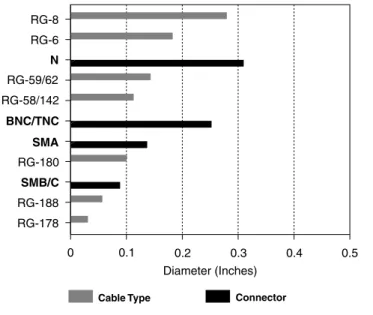
For example, miniature cables such as RG 188 are most
practically terminated to subminiature connectors such
as SMB and SMC styles. Figure 3 illustrates the interface
diameters of each connector type and the dielectric
out-side diameter (DOD) of popular RG cables. It is most
eco-nomical to select a connector that terminates to a cable
with a dielectric diameter close in size to the connector’s
interface diameter. The product information sections of this
catalog have been organized so that all connector
con-struction types are grouped together by cable size. This
allows easy selection of the connector construction best
suited for the application.
Tyco Electronics continually looks at new cable types
and will release new part numbers based upon general
market or specific customer needs. If you cannot find a
Tyco Electronics part number for a specific cable type,
please contact one of our sales locations or your local
distributor to make an inquiry.
Tyco Electronics offers a wide range of connector
configu-rations for terminating to printed circuit boards. Also
avail-able are connectors which allow the interconnection of one
interface type to another.
By reviewing this catalog, a connector can be found to
match most any application. Since the RF connector is a
part of a transmission line system, make sure when
select-ing a new connector design, that it is compatible with the
overall system’s performance.
Construction
The construction of a connector will greatly affect the
purchase price. The connector tables in this catalog
include construction details that allow you to select
con-nectors that meet your requirements at the lowest price.
Commercial designs use lower cost materials, such as zinc
diecast bodies, polypropylene insulators and silver-plated
contacts. Specific details of connector construction are
listed in each product section of this catalog.
The materials used affect both performance and cost.
Common base metals include brass, beryllium copper and
stainless steel. The most common plating used for the
cen-ter contact is gold because of its low contact resistance,
superior mating properties and corrosion resistance.
TEFLON, polypropylene and polymethylpentene (TPX) are
the most common connector dielectrics. TEFLON offers the
lowest loss, the most stable electrical properties and
high-est operating temperature. But since it cannot be injection
molded, manufacturing is more costly than other materials.
Be certain, when specifying connectors, that the
tempera-ture and voltage limitations are taken into consideration.
Assembly
There are several methods of assembly or termination, but
they can be categorized into two major areas: (1) Solder
center conductor and clamp braid (Category A) and (2)
Crimp center conductor and crimp braid. Other methods
are derived from combinations of the above, (e.g., solder
center conductor and crimp braid. Method (1) (Category
A) is generally used where no specialized tools are
avail-able, such as with field installations. With the development
of low cost assembly tools, method (2) is becoming more
popular for field installation.
Crimping
is preferred in most manufacturing environments
where assembly tooling is available because terminations
can be made in the least amount of time and with the
greatest reliability. The design of crimp tools assures that
every termination is made the same; this cannot be done
with a clamp design without further testing or inspection.
Figure 4 illustrates the difference between braid crimping
using AMP “O” crimp and the industry-standard hex crimp.
The AMP “O” crimp gives a more consistent pressure on
the outer collar. In addition, the crimp of the center
con-ductor provides superior VSWR as shown in Figure 5.
Benefits derived by using AMP “O” crimp:
■
No soldering of center contact is required. This
allevi-ates all prospective problems associated with the
sol-dering process such as excess solder, cold solder
joints and overheating the dielectric.
■
Fewer parts resulting in less assembly errors
■Braid crimping which eliminates the need for the
combing, screwing and torquing associated with the
braid clamp.
RG-8 RG-6 N RG-59/62 RG-58/142 BNC/TNC SMA RG-180 SMB/C RG-188 RG-178Cable Type Connector
0 0.1 0.2
Diameter (Inches)
0.3 0.4 0.5
Figure 3
TEFLON is a trademark of E.I. Dupont de Nemours and Company. TPX is a trademark of Mitsui Chemicals America, Inc.
7
7-16 Series Connectors
Product Facts
■
Designed for cellular
base-stations, control component,
antenna and broadcast
applications
■
Available in White Bronze
plating
■
Minimizes Intermodulation
Distortion by the use of
non-ferrous materials
■Hex knurl for wrench
tightening
■
Available for several
popular RG cable sizes in
solder-clamp and
crimp-crimp attachment styles
Tyco Electronics offers a
comprehensive range of
7-16 Connectors to suit
today’s challenging Wireless
Infrastructure Market. This
market demands reliable,
intermodulation sensitive
connectors that
accommo-date higher power.
Tyco Electronics 7-16
Coaxial Connector Series
provides reliable,
intermod-ulation- minimizing solutions
that also provide a logical
alternative to N Series
con-nectors in high power
appli-cations where a more
rugged interface design is
required. Typical examples
of this include transmitter to
antenna links and channel
switching networks.
The 7-16 Series conforms to
CECC 22190 and IEC 169-4
specification standards and
has a 2.7kV working voltage
at the connector interface
and maximum power
handling capability of 4kW.
The series has been
designed for these
demanding environments
and can withstand a
mini-mum of 500 mating cycles.
Popular RG cable sizes are
covered in both
solder/clamp and crimp
attachment styles. Two
piece combination
connec-tors adapt to straight or
right-angle configurations,
minimizing the number of
different part codes needed
by the customer. Series N to
7-16 between series
adapters facilitate the
transi-tion between system
inter-faces as well as providing a
test interface.
The increased customer
demand for greater channel
capacity combined with
increased sensitivity of
receivers has exposed the
IMD (Intermodulation
Distortion) phenomenon.
To address this problem
7-16 Connectors have been
designed to reduce
IMD through the use of
non-ferrous base materials and
by silver plating of the
elec-trical path. The proprietary
White Bronze plating
tech-nique is standard, providing
high corrosion resistance,
low porosity, scratch
resistance, low RF loss
and a non-magnetic finish.
Incorporation of hex-knurl
coupling nuts allow for
hand or wrench tightening
of connectors, depending
upon the application.
Tyco Electronics is a
global ISO 9001 certified
manufacturer and maintains
a complete in-house
Intermodulation Testing
facility. Connector part
numbers shown form just a
small part of the extensive
interconnect package that
Tyco Electronics offers for
the professional wireless
and telecom markets.
Related Product Data
N Connectors — Pages 20-25Application Notes — White Bronze — Appendix B Intermodulation — Appendix C
Between Series Adapters
For 7-16 Series Between Series Adapters, see pages 251-260.
8
Materials
Female Contacts (inner and outer) Beryllium Copper
Other Metal Parts Brass
Insulators Fluorocarbon Polymer
Gaskets Silicone Rubber
Finishes
Parts in the electrical path Silver over copper
Other Metal Parts White Bronze
Electrical
Frequency Range DC-7GHz
Impedance 50 Ohms
Insulation Resistance 10,000 Megohms Minimum 2.7kV (connector)
Maximum Working Voltage rms (sea level) 1.4kV (versions for RG 213, 214 and 393) Maximum Proof Voltage rms (sea level) 2.7kV (connector)
1.4kV (versions for RG 213, 214 and 393) Center Contact Resistance 0.8 milliohm (max.) after conditioning
Insertion Loss <1.5dB to 5 GHz
VSWR 1.02 + 0.03f up to 7 GHz
where f is measured in GHz
Intermodulation Better than –150dBc
Mechanical
Coupling Torque 18.5 – 22 ft.-lbs.
Proof Torque 25 ft.-lbs.
Mechanical Endurance 500 mating cycles
Environmental
Temperature Rating –55°C to +155°C
9
7-16 Series Connectors (Continued)
Straight Cable Plug
Solder/Solder
Ø 32.00 ± 0.20 [1.260 ± .008] 50.35 ± 0.50 [1.982 ± .020] 4.50 [.177]Typ. 23.50 [.925]Typ. Ø 16.50 ± 0.20 [.650 ± .008]Cable Type Body Plating Part No.
1/2" Corrugated White Bronze/Gold 1460159-1
43.5
[1.71]
32.0
[1.26]Dia.
Cable Type Body Plating Part No.
RG 8A/U, RG 213/U White Bronze 6331959-1
RG 9B/U, RG 214/U White Bronze 6362765-1
43.0 [1.69] 34.3 [1.35] 32.0 [1.26]Dia. 36.0 [1.42] Assembled
Cable Type Body Plating Part No.
RG 58C/U, RG 141A/U White Bronze 6408028-1
RG 213/U White Bronze 6408030-1
RG 214/U White Bronze 6312113-1
36.0 [1.42] 32.0 [1.26] 43.0 [1.69]
Right-Angle Cable Plug
Solder/Crimp
Straight Cable Plug
Crimp/Crimp
10
Cable Type Body Plating Part No.
RG 8A/U, RG 213/U White Bronze 6408032-1
RG 9B/U, RG 214/U White Bronze 6408033-1 44.0 [1.73] 46.5 [1.83] 24.8 [0.98] 17.2 [0.68] 5.00 [0.20] Assembled 24.8 [0.98] 29.5 [1.16]Dia. 3.70 [0.15] Dia 4 Holes. Mounting Detail
Straight Panel Mount
Cable Jacks
Crimp/Crimp
Panel Socket Launcher
Body Plating Part No.
White Bronze 6311225-1 White Bronze 1460052-2 21.6 [0.85] 5.00 [0.20] 24.8 [0.98] 24.8 [0.98] 29.5 [1.16]Dia. 3.70 [0.15] Dia 4 Holes. Mounting Detail
Right-Angle Cable Plug
Solder/Clamp
43.0 [1.69] 32.0 [1.26] 23.2 [0.91]Cable Type Body Plating Part No.
RG 55B/U, RG 58C/U,
RG 141A/U, RG 142B/U, White Bronze 6408026-1
RG 223/U, RG 400/U T-Flex 402 Silver 6328873-1 43.0 [1.69] 32.0 [1.26]Dia. 47.2 [1.86]
Cable Type Body Plating Part No.
RG 213/U, RG 214/U,
RG 393/U White Bronze 6408027-1
RG 8A/U, RG 9B/U,
RG 213/U, RG 214/U White Bronze 6408038-1
7-16 Series Connectors (Continued)
Right-Angle Panel Jack
Solder/Clamp
46.3 [1.82] 24.8 [0.98] 17.2 [0.68] 5.00 [0.20] 24.8 [0.98] 29.5 [1.16]Dia. 47.2 [1.86] 3.70 [0.15] Dia 4 Holes. Mounting DetailCable Type Body Plating Part No.
RG 213/U, RG 214/U,
RG 393 White Bronze 6408036-1
RG 58C/U, RG 142B/U,
RG 223/U, RG 400/U White Bronze 6363527-1
46.3 [1.82] 24.8 [0.98] 17.2 [0.68] 5.00 [0.20] 34.2 [1.35] 24.8 [0.98] 29.5 [1.16]Dia. 36.7 [1.44] Assembled 3.70 [0.15] Dia 4 Holes. Mounting Detail
Cable Type Body Plating Part No.
RG 55B/U, RG 142B/U,
RG 233/U, RG 400/U White Bronze 6363524-1 RG 8A/U, RG 213/U White Bronze 6363525-1
RG 9B/U, RG 214/U White Bronze 6363526-1
Combination Panel Jack
Solder/Crimp
11
49.0 [1.93] 33.0 [1.30] 14.0 [0.55] 45.0 [1.77] Max PanelBody Plating Part No.
White Bronze 6408037-1
Bulkhead Adapter
Jack/Jack
12
Product Facts
■
Cellular operator protection
against EMP
(electro-magnetic pulses) caused
by lightning strikes
■Two different categories:
Surge protectors and
Quarter wave stub tuners
■For use in cellular
infra-structure including GSM,
DCS 1800, and PCS 1900
systems
■
Incorporates Gas Discharge
Tube (GDT) technology
Tyco Electronics has
devel-oped a unique series of
Lightning and EMP
protec-tion devices for use in
cellu-lar infrastructure including
GSM, DCS 1800, and PCS
1900 systems. These
devices are designed to
offer the cellular operator
protection against EMP
(electro-magnetic pulses)
caused by lightning strikes.
Direct or even near strikes
produce fast rising electric
fields within micro-seconds.
These fields generate high
voltage pulses through
unprotected antennas and
transmission lines which
lead to the primary
commu-nication equipment. High
voltage pulses can cause
extensive damage leading
to costly repairs as well as
significant loss of service to
subscribers. These
protec-tive devices come in two
different categories: surge
protectors and quarter wave
stub tuners.
To ensure that proper, low
level contact resistance is
established between the LP
device and mounting wall, it
is recommended that a
min-imum torque of 50 in/lbs /
5.65 n/m be applied to
tighten the connector
mounting nut. A
recom-mended minimum torque of
35 in/lbs / 3.95 n/m should
also be applied for
installa-tion of replacement surge
protector capsules to
ensure proper protection
performance.
In order to ensure that
resultant currents from
light-ning or EMP strikes do not
interfere with parallel
transmission lines within
protected electronic
equip-ment, surge protector
devices must be installed
with proper orientation.
The surge protector side
of the device should be
mounted in the unprotected
side of the equipment while
the mounting nut is
posi-tioned internally in the
protected area.
It is important when
plan-ning lightplan-ning protection,
that the user can estimate
the potential number of
direct strikes. This
informa-tion may influence the type
of device selected or the
requirement for routine
maintenance checks.
Significant attention must be
paid to the height of
sup-porting structure as this,
when related to the typical
number of thunderstorms in
a particular region, allows
us to estimate the
probabil-ity of a direct strike taking
place. To assist our
cus-tomers in this, the following
table and chart has been
included in this note. This
should enable lightning
pro-tection planners to establish
the likelihood of direct
strikes across a network
anywhere in the world.
Detailed application notes
are available for proper
selection of lightning
tection devices (surge
pro-tectors & stub tuners) as
well as intermodulation and
White Bronze plating.
Number of Thunderstorm hmax/m hmax/m hmax/m
Days per year 10% 20% 50%
05 28 39 61 10 18 26 40 15 14 20 31 20 12 17 26 30 9.4 13 20 40 7.9 11 17 50 6.9 9.5 15 70 5.6 8.0 12 90 4.8 7.0 10.6 130 3.9 5.5 8.5 150 3.5 5.0 7.7 180 3.1 4.4 6.9
Table 1: Maximum height of supporting building for a given number of thunderstorm days (when hmax is exceeded,
probability of direct strike to supporting building within 15 years is greater than 10% for hmax values given in second column, 20% for hmax values given in third column and 50% for hmax values given in the fourth column).
Selecting your RF Coaxial
Lightning Protection Device
Between Series Adapters
For 7-16 Series and N Series Between Series Adapters, please see pages 251-260.
13
Surge Protectors
Advantages
■Broadband
■
Allows DC bias on the transmission line.
(critical for applications using mast top
electronics.)
■
No harmonic passband
■
Ease of retrofitting antenna sights
■
GDT easily accessible for replacement
Limitations
■
Routine maintenance recommended
■
3 GHZ maximum frequency
■
Initial pass-through voltage
Selection of a Lightning
Protection Device
At right are the basic
advantages and limitations
for both types of protection
to use in the proper
selec-tion for your applicaselec-tion.
These devices incorporate Gas Discharge
Tube (GDT) technology. A GDT is a
hermetically sealed tube containing an
inert gas. The tube is inserted in the side
of the device through an easily accessible
weather sealed port. During normal
operation the tube is inactive. When an
installation is struck by lightning, a high
voltage impulse will appear on the coaxial
line. As the impulse amplitude rises, a level
is reached where the impulse surpasses
the dynamic voltage threshold of the tube
and the electrodes arc over to discharge
the energy to ground. Prior to activation of
the tube, there will be a short period of time
where energy will be present on the line.
This
residual pulse
is equal to the dynamic
voltage threshold of the tube. The
maxi-mum impulse voltage a tube can handle
without discharging is referred to as the
impulse sparkover voltage
. This capacity
of the GDT is quoted as follows:
Characteristic Symbol Definition Impulse Typical Value
Impulse Dynamic
sparkover Uzdyn voltage 1kV/µS 650V voltage threshold
In the case of the referenced chart,
the voltage will rise at one kilovolt per
microsecond and the tube will fire after 650
nanoseconds. During activation a small
percentage of voltage (called arc voltage)
will still pass through. This will be
approxi-mately 30 volts. When the pulse subsides,
the tube again becomes inactive leaving a
small
residual voltage
on the line. A direct
lightning strike results in an impulse current
of high amplitude. The capability of a device
to protect a system is defined as the
impulse discharge current
rating. This is
defined as the peak current of an impulse
which the device can withstand ten times
(5 at each polarity at fixed intervals) without
affecting the device.
maximum impulse
discharge current
is the peak current of an
impulse the device can withstand once.
Surge protectors are often used in
applica-tions requiring a standing DC line voltage.
This is typical in applications with mast top
electronics. The maximum voltage capacity
of a surge protector prior to it surpassing
the static voltage threshold and
discharg-ing it to ground is defined as its D.C.
Product Facts
■
Excellent for Broadband
Frequency Applications
■Field Replaceable Gas
Discharge Tube
■Available Interfaces
Facilitate Retrofit
Capabilities
■
Low VSWR up to 2.5GHz
■Specialized White Bronze
14
sparkover voltage
. This capacity is quoted
as follows:
Characteristic Symbol Definition Impulse Typical Value
d.c. Static
sparkover Uzstat voltage n/a 230V voltage threshold
In these applications it is important to
select a device that will assure the tube
can return to its inactive state after the
passage of a surge. This feature of the
Surge protector is known as the
holdover
voltage
. If the device continues to conduct,
the protected line will be short circuited
and the tube will heat up (glow mode). If
left in this state, the tube can overheat and
destruct. GDT’s have a finite life span which
is inversely proportional to the energy
dissipated. At extremes it is possible to
reach a level where the tube is unable to
discharge all the energy and is destroyed.
It is therefore necessary to schedule
rou-tine maintenance checks and periodically
replace the tube within the surge protector.
Surge protectors offer excellent lightning
protection for broadband systems and are
usable up to 3 GHz. Standard interfaces
include 7-16, N, and SMA. Configurations
include straight and bulkhead mounted
adapters which allows for ease of
assimila-tion into existing systems.
Requirement Detail
Electrical
Frequency Range DC to 3GHz
Impedance 50Ω
VSWR Performance ≤1.33:1
Insertion Loss (Typical) 0.45dB
Impulse Discharge Current (8/20µs, multiple strike) 20kA Maximum Impulse Discharge Current (8/20µs, single strike) 50kA Dynamic Sparkover Voltage, NEMP (1kV/µs) 2,000V Dynamic Sparkover Voltage, LEMP (1kV/µs) 800V Dynamic Sparkover Voltage, Static (<100V/µs) 90V*
Materials
Body Parts Brass
Gaskets Silicone Rubber
Female Contacts Beryllium Copper
Male Contacts Brass
Insulators P.T.F.E.
Environmental
Operating Temperature Range -45° C to +85° C
Relative Humidity up to 100%
* Determined by gas tube used, can be higher than value shown.
Specifications
Frequency Range DC to 3GHz Contact Plating Gold Body Plating White Bronze Max Panel 10.00mm Compliant With CECC22210/
CEC22110 Coupling Torque 0.7-1.1Nm Proof Torque 1.7Nm both ends Endurance 500 Matings Recommended Mounting Hole 53.8 [2.12] 13.6 [0.54] Ref. 25.4 [1.00] Sq. 21.5 [0.85] Ref. 14.0 [0.55] 16.0 [0.63] Dia.
N Series Jack to SMA
Bulkhead Jack Adapter
Part Number 6312079-1
15
Surge Protectors (Continued)
Frequency Range DC to 3.0 GHz Contact Plating Gold Body Plating White Bronze Max Panel 10.00mm Compliant With CECC22210 Coupling Torque 0.7-1.1 Nm Proof Torque 1.7 Nm Endurance 500 Matings Recommended Mounting Hole 53.8 [2.12]Ref. 25.4 [1.00] Sq. 16.0 [.063] Dia. 13.6 [.054]
N Series Jack to N Series
Bulkhead Jack Adapter
Part Number 6312138-1
Frequency Range DC to 3.0 GHz Contact Plating Silver Body Plating White Bronze Compliant With CECC22190 Coupling Torque 25 - 30 Nm Proof Torque 35Nm Endurance 500 Matings 31.9 [1.25] 56.5 [2.23] Ref. 34.0 [1.34] Dia. Ref.
7-16 Plug to 7-16
Jack Adapter
Part Number 6312121-1 d.c. Sparkover Voltage: 230V ± 46V Impulse Sparkover Voltage: 700V typ. (1kV/mS) (900V max) Glow Discharge Voltage: 72V Arc Discharge Voltage: 10V a.c. Discharge Current: 20A (1 sec, 50Hz)Impulse Discharge Current: 20kA (50kA for (8/20mS waveform) one strike) Insulation Resistance (@100V): 10GW Capacitance: 2pF
Gas Discharge Tube
Replacement
Part Number 1402314-1
16
These devices are three port
coaxial connectors. The third
port extending from the main
through path is terminated in
a short circuit at a
pre-deter-mined distance calculated to
be exactly one quarter
wave-length at the desired center
frequency (see graph).
Unlike surge protectors, this
design eliminates concerns
about residual pulse,
sparkover voltage and
resid-ual voltage ensuring greater
protection for sensitive
electronic equipment. As
opposed to surge
protec-tors, stub tuners will absorb
lightning strikes without
need for replacing
compo-nents. These devices yield
very low VSWR and feature
high attenuation within a
rel-atively narrow pass-band
(+/- 70 MHz) but are
appli-cation specific. Stub tuners
also pass energy in bands
that are harmonically related
to the fundamental center
frequency. The graphs
below show a typical test
impulse and the response of
a stub tuner.
Stub tuners are classified
into two broad categories—
simple and broadband. The
simple stub tuner exhibits a
V-shaped response on the
VSWR vs. frequency plot.
The trough of the V is
designed to occur at the
required Fo and the
band-width is restricted to
approx-imately 8%. The broadband
tuner employs extra RF
tech-niques, similar to multiple
cavity filtering, which
increase the effective
band-width by approximately 20%.
Tyco Electronics offers a
wide variety of stub tuners
for the most popular
fre-quency bands to facilitate
purchase without need for
custom design and
manu-facturing. Designs exist for
GSM, PCS 1900, DCS 1800
frequencies with standard
industry interfaces
includ-ing SMA, 7-16, and Type N.
Configurations include
cable assemblies, cabled
connectors, and adapters
for ease of assimilation into
existing systems. Stub
tuners are maintenance free
since they incorporate no
active components though
it is recommended that a
check of the stub tuner
affixment be made following
heavy discharges at an
installation.
Product Facts
■
Ideal for use with GSM,
PCS and DCS
■
Maintenance Free Operation
■Low VSWR Within Specified
Bandwidth
■
Configurations include
direct attachments to Cable
variants
■
Optional White Bronze
Finish
li Vi Vr lr 0.3 1.0 1.9 0.5 0 V T1 = 1.67T T2 T 01 T1 t 326.400 110.308 V kA 244.800 94.5588 V kA 163.200 78.8088 V kA 81.6000 63.0588 V kA 0.0 47.3088 uV kA -81.600 31.5588 V kA -163.20 15.8088 V kA -244.80 58.80 V A -326.40 -15.691 V kA -640.0nS, 80.033280 V 10.98uS, 49.45920kA0.0nS 20.00uS 40.00uS 60.00uS 80.00uS 0.0nS 20.00uS 40.00uS 60.00uS 80.00uS
λ
/4 Shorting Stub Basics
Typical Test Impulse
Typical
λ
/4 Test Response
Advantages
■Low VSWR in
pass-band
■Minimal maintenance
■Pass-through voltage
eliminated
■No sparkover or
resid-ual voltage concerns
■
Ease of retro-fitting
antenna sights
Limitations
■
Frequency specific
■
Harmonic passband
■
Does not allow DC bias
on transmission line
λ
/4 Stub Tuners (Continued)
17
Requirement Detail (Type-N, 7-16)
Electrical
Impedance 50Ω
VSWR Performance in Band ≤1.2:1 Insertion Loss (Typical) 0.2dB DC Resistance (stub outer to inner) 1mΩ Dynamic Voltage @ 250A/ms ≤15V Residual Voltage @ 2500A, 8/20µs ≤15V Outer Conductor Contact Resistance 10mΩ DC Resistance (through-path center contact) 100mΩ
Materials
Body parts Brass
Gasket Silicone Rubber
Female contacts Beryllium Copper
Male Contacts Brass
Insulators P.T.F.E.
Environmental
Operating temperature range -45°C to +85°C Relative humidity (non-condensing) up to 100%
Bandwidth ± 70 MHz Center Frequency 1795 MHz Contact Plating Silver Body Plating Silver Max Panel 10.00mm Compliant With CECC22210 Coupling Torque 0.7-1.1Nm Proof Torque 1.7Nm Endurance 500 Matings Recommended Mounting Hole 62.9 [2.48] 25.4 [1.00] Sq. Ref. 16.0 [0.63]Dia. 23.5 [0.92] Ref. 54.7 [2.15] Ref. 13.6 [0.54] 42.0 [1.65] Ref.
DCS 1800
Type N Clamp
Bulkhead Jack
Cable Part No.
T-Flex402 6329818-1
Bandwidth ± 70 MHz Center Frequency 1795 MHz Contact Plating Silver Body Plating White Bronze Max Panel 8.00mm Compliant With CECC22190 Coupling Torque 25 - 30Nm Proof Torque 35Nm Endurance 500 Matings Recommended Mounting Hole 77.6 [3.06]Ref. 44.6 [1.76] Ref. 67.0 [2.64] Ref. 44.9 [1.77] 30.5 [1.20] 3.20 [0.13] 17.5 [0.69] Dia. Ref.
7-16 Jack to 7-16
Bulkhead Jack Adapter
Part Number 6361137-1
18
Bandwidth ± 70 MHz Center Frequency 1795 MHz Contact Plating Silver Body Plating Silver Max Panel 10.00mm Compliant With CECC22210 Coupling Torque 0.7-1.1Nm Proof Torque 1.7Nm Endurance 500 Matings Recommended Mounting Hole 62.9 [2.48] 23.5 [0.92] Ref. 25.4 [1.00] Sq. 42.0 [1.65] Ref. 54.7 [2.15] Ref. 16.0 [0.63] 13.6 [0.54] Ref. Dia.
DCS 1800
(Continued)Type N Crimp
Bulkhead Jack
Cable Part No.
RG58C/U 1329819-1
PCS 1900
Bandwidth ± 70 MHz Center Frequency 1920 MHz Contact Plating Silver Body Plating Silver Max Panel 10.00mm Compliant With CECC22210 Coupling Torque 0.7-1.1Nm Proof Torque 1.7Nm Endurance 500 Matings Recommended Mounting Hole 62.9 [2.48] [1.00]25.4 Sq. Ref. 16.0 [0.63]Dia. 23.5 [0.92] Ref. 52.9 [2.08] Ref. 13.6 [0.54] 40.2 [1.58] Ref.
Type N Clamp
Bulkhead Jack
Cable Part No.
T-Flex 402 1312137-1
Bandwidth ± 70 MHz Center Frequency 1795 MHz Contact Plating Silver Body Plating Silver Max Panel 10.00mm Compliant With CECC22210 Coupling Torque 0.7-1.1Nm Proof Torque 1.7Nm Endurance 500 Matings Recommended Mounting Hole 57.3 [2.26] 25.4 [1.00] Sq. Ref. 16.0 [0.63]Dia. 23.5 [0.93] Ref. 10.0 [0.39] 54.7 [2.15] Ref. 13.6 [0.54] 42.0 [1.65] Ref.
Type N Jack to Type N
Bulkhead Jack Adapter
Part Number 1361138-1
Bandwidth ± 70 MHz Center Frequency 925 MHz Contact Plating Silver Body Plating White Bronze Max Panel 8.00mm Compliant With CECC22190 Coupling Torque 25 - 30Nm Proof Torque 35Nm Endurance 500 Matings Recommended Mounting Hole 77.6 [3.06] 44.9 [1.77] Ref. 27.4 [10.8] Ref. 93.4 [3.68] Ref. 30.5 [1.20] 17.5 [0.69] 71.0 [2.79] Ref. Dia. Dia. Ref.
GSM
7-16 Bulkhead Jack to
7-16 Bulkhead Jack
Cable Part No.
T-Flex 402 Cable 6408399-1
λ
/4 Stub Tuners (Continued)
19
Bandwidth ± 70 MHz Center Frequency 1920 MHz Contact Plating Silver Body Plating Silver Max Panel 10.00mm Compliant With CECC22210 Coupling Torque 0.7-1.1Nm Proof Torque 1.7Nm Endurance 500 Matings Recommended Mounting Hole 62.9 [2.48] 25.4 [1.00] Sq. Ref. 16.0 [0.63]Dia. 23.5 [0.92] 52.9 [2.08] Ref. 13.6 [0.54] 40.2 [1.58] Ref.
PCS 1900
(Continued)Type N Crimp
Bulkhead Jack
Cable Part No.
RG58 C/U 6312139-1
Bandwidth 1920 MHz Center Frequency ± 70 MHz Contact Plating Silver Body Plating Silver Max Panel 8.00mm Compliant With CECC 22190 Coupling Torque 25-30 Nm Proof Torque 35 Nm Endurance 500 Matings Recommended Mounting Hole 38.0 [1.50] 72.7 [2.86] 24.6 [0.97] Ref. 4.00 [0.16] Dia. Ref. 27.4 [1.08] Ref. 29.5 [1.16]Dia. 27.5 [1.08] 40.2 [1.58]Ref. Ref. Ref.
7-16 Clamp Bulkhead Jack
Cable Part No.
T-Flex402 6312123-1
Bandwidth 1920 MHz Center Frequency ± 70 MHz Contact Plating Silver Body Plating White Bronze Max Panel 8.00mm Compliant With CECC 22190 Coupling Torque 25-30 Nm Proof Torque 35 Nm Endurance 500 Matings Recommended Mounting Hole 77.6 [3.06]Ref. 44.9 [1.77] 17.5 [0.69] 30.5 [1.20] 42.2 [1.66] Ref. 64.6 [2.54] Ref. Dia. Ref.
7-16 Bulkhead Jack to
7-16 Bulkhead Jack Adapter
Part Number 6312124-1
Bandwidth ± 70 MHz Center Frequency 1920 MHz Contact Plating Silver Body Plating Silver Max Panel 10.00mm Compliant With CECC22210 Coupling Torque 0.7-1.1Nm Proof Torque 1.7Nm Endurance 500 Matings Recommended Mounting Hole 57.3 [2.26] 13.6 [0.54] Ref. 25.4 [1.00] Sq. 40.0 [1.58] Ref. 52.7 [2.08] Ref. 16.0 [0.63] Dia.
Type N Bulkhead Jack to
Type N Bulkhead
Jack Adapter
Part Number 6361139-1
20
The Tyco Electronics
N Connector, featuring a
15.88 [5/8] - 24 threaded
coupling for optimum
stability, is highly suited for
critical applications and
environments. This medium
sized connector can
with-stand shock and vibration to
assure a low noise level and
has a constant impedance
of 50 ohms. It also features
a captive center contact
and provides excellent
per-formance at frequencies up
to 11 GHz, with voltages to
1000 volts rms.
This Tyco Electronics
con-nector offers the added
benefits of low overall
applied cost with a
labor-saving two-crimp assembly.
The contact is simply
crimped to the cable’s
center conductor, then both
braid and cable support are
simultaneously crimped to
complete the termination.
N Series Connectors are
available in standard plug,
jack, panel jack, bulkhead
jack and right-angle plug
configurations. Those
connectors with a military
designation (M39012) are
furnished in accordance with
all requirements of
specifica-tion MIL-C-39012, Class II,
Category B.
Materials
Brass— QQ-B-626 Beryllium Copper— QQ-C-530 Dielectric— TEFLON TEFLON— MIL-P-19468 Copper, Annealed— QQ-C-576 Phosphor Bronze— QQ-B-750 Silicone Rubber— ZZ-R-765Plating
Body— Silver per QQ-S-365 Nickel per QQ-N-290 Center Contact— Gold per MIL-B-45204Electrical Characteristics
Nominal Impedance— 50 ohmsWorking Voltage— 1000 volts, rms at sea level
Frequency Range— 0 to 11 GHz
Voltage Standing Wave Ratio (VSWR)—
Straight Plug or Jack — 1.3:1 max. Right-Angle Plug —
1.35 max. at 0 to 9.0 GHz 1.50 max. at 9.0 to 11.0 GHz
Contact Resistance— Outer Contact — 0.2 milliohms Center Contact — 1.0 milliohms Right-Angle — 2.5 milliohms
Insulation Resistance— 5000 megohms min.
Dielectric Withstanding Voltage— 2500 Volts, rms at sea level
RF Leakage— MIL Type, -90 dB min. at 2 to 3 GHz
RF Insertion Loss— MIL Type, 0.15 dB max. at 10 GHz
Right-Angle Plug, 0.3 dB max. at 10 GHz
Corona Level— MIL Type, 500 volts min. at 21 336 m [70,000 ft.]
Terminator—
Resistance — 50 ohms ±1% Power Rating — 1.0 watt max.
Product Facts
■
Designated connectors are
MIL-C-39012, Class II,
Category B qualified
■Captive center contacts
■Completely crimpable
application – one hand tool
crimps all cables with
single or double braided
shields of a given size
■Impedance matching crimps
■Broad band performance –
low VSWR
■
Superior cable retention
■TEFLON dielectric
■Silver or nickel finish
■Fully intermateable with
MIL-C-39012 connectors
■Listed under the Component
Program of Underwriters
Laboratories Inc.,
File No. E81956
■Recognized under the
Component Program of
Underwriters
Laboratories Inc.,
File No. E81956
■Certified by Canadian
Standards
Association
File No. LR 7189
R R RMechanical Characteristics
Mating/Unmating— Threaded cou-plingCable Attachment — Crimp type -center contact and braid
Coupling Nut Retention— 445 N [100 lbs.] min.
Cable Retention— 400 N [90 lbs.] min. RG 214/U Cable
Durability— 500 cycles per MIL-C-39012
Captive Contact— 27 N [6 lbs.] min. axial retention, either direction
Environmental Characteristics
Temperature Range—MIL Type, -65°C to +165°C Commercial, -55°C to +85°C
Vibration— MIL-STD-202, Method 204, Test Cond. B
Shock— MIL-STD-202, Method 213, Test Cond. I
Moisture Resistance— MIL-STD-202 Method 106
Salt Spray— MIL-STD-202, Method 101, Test Cond B
Temperature Cycling— MIL-STD-202, Method 107, Test Cond. B (except high temperature is +85°C)
Note: All data pertains to use with MIL-C-39012 specified cables only.
Between Series Adapters
For N Series Between Series Adapters, see pages 251-260.
TEFLON is a trademark of E.I. Dupont de Nemours and Company.
21
N Series Connectors, 50 Ohm (Continued)
Plugs
M39012/
RG/U Termination Body
Military No. and/ Dim. Integral Die Hex Across Flats Notes Part No.
Cable Type Plating or Comments L Hand Tool Center Braid
O Crimp Nickel Knurl Collar 42.85 220045-2 — — 1 1-5225661-2
58, 58A, 1.687
58B, 58C
O Crimp Silver Knurl Collar 42.851.687 220045-2 — — 1 5225361-1
O Crimp Nickel Knurl Collar 42.85 220045-2 — — 1 1-5225661-3
223, 1.687
55, 55A, 55B
O Crimp Silver Knurl Collar 42.851.687 220045-2 — — 1 5225361-2
Knurl Collar 42.85 220045-2 — — 1, 3 5225392-2
142, 142A O Crimp Silver 1.687
142B, 400 Knurl Collar 42.85
1.687 220045-2 — — 1 5225361-4
O Crimp Nickel Knurl Collar 41.35 220045-2 — — 3 5225699-1
142, 142A 1.628
142B
Knurl Collar 39.40 58436-1 1.73 5.41 2 5415232-4
Hex Crimp Nickel 1.550 .068 .213
115A,
BELDEN 89880, O Crimp Nickel Knurl Collar 42.85 220015-1 — — 3 5225092-8
9880 1.687
BELDEN 9880 Hex Crimp Nickel Knurl Collar 39.401.550 58485-1 2.54.100 10.90.429 2 1-415232-0
402 Semi Rigid Solder Nickel Knurl Collar 24.6 — — — — 6057088-1
(.141) .970
405 Semi Rigid Solder Nickel Knurl Collar 24.6 — — — — 6057094-1
(.085) .970
O Crimp Nickel Knurl Collar 42.851.687 220015-1 — — — 1-5227086-0
O Crimp Nickel Knurl Collar 42.85 220015-1 — — — 5225661-2
8, 8A, 213 1.687
O Crimp Silver Knurl Collar01B0007 42.851.687 220015-1 — — 3 51692-2
O Crimp Nickel Knurl Collar 47.221.859 220015-1 — — 3 5225662-2
11, 11A, 216 O Crimp Silver Knurl Collar01B0013 42.851.687 220015-1 — — 3 51692-4
BELDEN 9292 O Crimp Nickel — 47.221.859 220015-1 — — 3 1-5225662-8
393 Hex Crimp Nickel Hex Collar 39.401.550 58485-2 3.25.128 10.90.429 2 5414160-5
BELDEN 8214 O Crimp Nickel Knurl Collar 42.851.687 220015-1 — — — 1-5225661-6
O Crimp Nickel Knurl Collar 42.85 220015-1 — — — 5225661-1
9, 9A, 9B, 1.687
214
O Crimp Silver Knurl Collar01B0008 42.851.687 220015-1 — — 3 51692-1
9, 214 Hex Crimp Nickel Hex Collar 39.401.550 58485-1 2.54.100 10.90.429 2 5415232-7
LMR 240 Hex/Solder Silver Hex Collar 29.741.171 — — 6.81.268 — 6274532-1
Notes:1Hand Tool 69710-1, with Die Insert 220062-1, is available to terminate these connectors. The 626 Pneumatic tool system can also be used.
2Die Set Crimp Tool — PRO-CRIMPER II Hand Tool, P/N 354940-1 or 626 Series Pneumatic Tool with 679304-1. 3Weatherproof. L Max. 19.05 [.750] Dia. Max.
MIL Type
Dual Crimp
L Max. 21.01 [.827] Dia. Max.Semi-Rigid Cable
L Max. 21.01 [.827] Dia. Max.Hex
Dual Crimp
Note: Part Numbers are RoHS compliant except:Indicates non-RoHS compliant.
BELDEN is a trademark of Belden Wire and Cable Company.
22
21.01 [.827] Dia. Max. 35.86 [1.412]Max. L Max.Right-Angle Plugs,
Crimp
Jacks
L Max. 15.93 [.627] Dia. Max. M39012/RG/U Termination Body Military No. and/ Dim. Integral Die Hex Across Flats
Notes Part No.
Cable Type Plating
or Comments L Hand Tool Center Braid
58A, 58C Hex Crimp Nickel Hex Collar 57.792.275 58436-1 1.73.068 5.41.213 1 5415255-1
142, 142A, Hex Crimp Nickel Hex Collar 57.79 58436-1 1.73 5.41 1 5415255-2
142B 2.275 .068 .213
O Crimp Nickel Knurl Collar 57.79 220015-1 — — — 5225669-2
8, 8A, 213 2.275
O Crimp Silver Knurl Collar05B0002 57.792.275 220015-1 — — — 225014-2
8, 213 Hex Crimp Nickel Hex Collar 57.792.275 58485-1 2.54.100 10.90.429 1 5415255-3
393 O Crimp Silver Knurl Collar 62.312.453 220015-1 — — 1,3 225389-6
O Crimp Nickel Knurl Collar 57.79 220015-1 — — — 5225669-1
9, 9A, 9B 2.275
214
O Crimp Silver Knurl Collar05B0003 57.792.275 220015-1 — — — 225014-3
9, 214 Hex Crimp Nickel Hex Collar 57.792.275 58485-1 2.54.100 10.90.429 1 5415255-4
Notes:1Die Assembly compatible with Crimp Tool — PRO-CRIMPER III Hand Tool, P/N 354940-1, 626 Series Pneumatic Tool 1213855-1, SDE Battery Tool Kit
1725837-1, or SDE Electric Terminator 1490076-2. 3Weatherproof.
M39012/
RG/U Termination Body
Military No. and/ Dim. Integral Die Hex Across Flats Notes Part No.
Cable Type Plating or Comments L Hand Tool Center Braid
58A, 58C O Crimp Nickel — 44.831.765 220045-2 — — 2, 3 1-5225664-2
142, 142A, Hex Crimp Nickel — 41.28 58436-1 1.73 5.41 2 5415242-2
142B 1.625 .068 .213
8, 8A, O Crimp Silver 02B0008 49.20 220015-1 — — 3 225093-2
213 1.937 8, 213 O Crimp Nickel — 49.201.937 220015-1 — — 2, 3 5225664-2 9, 9A, 9B, O Crimp Silver 02B0009 49.20 220015-1 — — — 225093-1 214 1.937 9, 214 O Crimp Nickel — 49.201.937 220015-1 — — 2, 3 5225664-1
393 Hex Crimp Nickel — 41.281.625 58485-1 2.54.100 10.90.429 2 5415242-6
402 Semi Solder Nickel — 26.70 — — — — 6057116-1
Rigid (.141) 1.051
Notes:1Hand Tool 69710-1, with Die Insert 220062-1, is available to terminate these connectors. The 626 Pneumatic tool system can also be used.
2 Die Assembly compatible with Crimp Tool — PRO-CRIMPER III Hand Tool, P/N 354940-1, 626 Series Pneumatic Tool 1213855-1, SDE Battery Tool Kit 1725837-1, or SDE Electric Terminator 1490076-2.
3 Weatherproof.