N-1000-III/IV
Installation and
Programming
Manual
TD1064 rev0400 - NCI ADEMCO Part # K4788i i i i i N-1000-III/IV Notices
Fire Safety Notice: Never connect any card reader devices or locks to door, gates or barriers without first consulting the local fire codes. You must consult with and get approval of, local fire officials before installing locks or devices on any doors that may be fire exits. Use of egress push buttons may not be legal. Single action exit may be required. Always obtain proper permits and approvals in writing before installing equipment.
Notice: This equipment has been tested and found to comply with the limits for a Class A digital device, pursuant to part 15 of the FCC Rules. These limits are designed to provide reasonable protection against harmful interference when the equipment is operated in a commercial environ-ment. This equipment generates, uses, and can radiate radio frequency energy and, if not installed and used in accordance with the instruction manual, may cause harmful interference to radio communications. Operation of this equipment in a residential area is likely to cause harmful interference in which case the user will be required to correct the interference at his own expense.
Notice: The information in this document is subject to change without notice.
Notice: This document and the data herein shall not be duplicated, used or disclosed to others for procurement or manufacturing, except as authorized with the written permission of Northern Computers, Inc. The information contained within this document or within the product itself is considered the exclusive property and trade secrets of Northern Computers, Inc. All information in this document or within the software product itself is protected by the copyright laws of the United States.
Notice: Any use of this product is subject to the terms and acceptance of the Northern Computers, Inc. “Software Agreement.” Please request a copy from Northern Computers, Inc. and review this agreement carefully.
IBM is a trademark and/or a registered trademark of Internationl Business Machines Corporation. MS-DOS, Windows, Windows NT, Windows ’95, Windows ‘98 are trademarks and/or registered trademarks of Microsoft Corporation in the United States and/or other countries. The use of Cotag, Wiegand, IDI, Continental, NCS, Dorado, Indala, Motorola & Hayes may or may not be registered trademarks/
technologies of those respective companies.
i i i i i i i i
iii iii iii iii iii N-1000-III/IV
Contents
Contents
Contents
Contents
Contents
UL Note... vi
New and Improved Features of the N-1000-III/IV ... vii
Section 1: Introduction/Access Control ... 1-1
Section 2: System Overview ... 2-1
2-1: N-1000-III/IV ... 2-1
2-2: Programming Devices ... 2-2
2-3: C-100-A1 Converter ... 2-4
2-4: N-485-PCI-2 or HUB-2 ... 2-4
2-5: PROM Versions ... 2-4
Section 3: Hardware Specifications ... 3-1
Section 4: Installation/Panel Layout ... 4-1
4-1: Four Reader Board (N-1000-IV only) ... 4-2
4-2: Terminal Blocks 1, 2, 3, 4 ... 4-4
4-3: Terminal Block 5 ... 4-6
4-4: Terminal Block 6 ... 4-6
4-5: Terminal Block 7 ... 4-8
4-6: Terminal Block 8 ...4-10
4-7: Terminal Block 9 ...4-10
4-8: DIP Switch Settings ...4-12
4-9: Jumpers ...4-14
4-10: Connectors ...4-15
4-11: LEDs ...4-16
4-12: Restart Button ...4-18
4-13: RAM Chip ...4-18
4-14: PROM Chip ...4-18
4-15: Additional Installation Information ...4-18
Section 5: Operation ... 5-1
5-1: Card Reader/Keypad Operation ... 5-1
5-2: Alarm Input Points ... 5-4
5-3: Relay Output Points... 5-5
5-4: Default Input Point/Output Point Interaction ... 5-6
5-5: Auto-Relock Operation ...5-14
5-6: Time Zone-Controlled Doors ...5-14
Section 6: Wiring Requirements ... 6-1
6-1: Card Readers ... 6-1
6-2: Four Reader Board (N-1000-IV Only) ... 6-3
6-3: Eleven Conductor Keypads ... 6-5
6-4: Alarm Input Points ... 6-7
6-5: Relay Output Points... 6-7
i v i v i v i v i v N-1000-III/IV
6-6: Communications ... 6-7
6-6-1: PC to C-100-A1 ... 6-7
6-6-2: C-100-A1 to Panel(s) ... 6-7
6-6-3: AEP-3 to N-1000-III/IV ... 6-8
6-6-4: PC to N-485-PCI-2 ...6-12
6-6-5: N-485-PCI-2 to Panel ...6-12
6-6-6: N-485-HUB-2 to Panel ... 6-13
6-6-7: N-485-HUB-2 to Modem ... 6-13
6-6-8: Bias and EOL with 485 Communication ... 6-14
6-7: Cable Specifications ...6-18
6-8: NCI Cable Part Numbers ... 6-19
6-9: Configurations for RS-232 Serial Communication Ports ... 6-20
Section 7: Locks and Suppression ... 7-1
Section 8: Grounding ... 8-1
Section 9: Power ... 9-1
Appendix A: Programming Quick Reference Guide ... A-1
Commands ... A-5
A Command ... A-5
C Command ... A-6
D Command ... A-8
E Command ... A-9
F Command ...A-10
G Command ... A-12
H Command ... A-13
I Command ...A-13
L Command ...A-14
M Command ... A-15
N Command ... A-16
O Command ... A-17
P Command ... A-18
R Command ... A-18
T Command ...A-19
V Command ... A-19
W Command (Used with the N-1000-III/IV only) ... A-20
Z Command ...A-21
OR’ing of Inputs ...A-21
Output Groups by Readers ...A-22
Appendix B: N-1000-III/IV Compared to N-1000-II... B-1
Appendix C: Troubleshooting ... C-1
N1000-III/IV Self-Test Capability ... C-3
v v v v v N-1000-III/IV
Preface
The N-1000-III/IV Installation Manual provides all information necessary for installation of N-1000-III, N-1000-III-X, N-1000-IV, and N-1000-IV-X control panels. All of the N-1000-III/IV versions have both the 20 mA and 485 multi-drop commu-nications interfaces.
The N-1000-III/IV can be used in existing N-1000-II/N-800 systems provided the existing panels have version 8.0 or higher firmware.
Note: When the N-1000-II/N-800 is configured for 485 (N-485-API-x), the firmware version must match the 485 version in the N-1000-III/IV.
The following table identifies the different features of each version of the N-1000 panel:
Version* Card Readers Matrix Keypads Alarm Inputs** Relay Outputs Cards*** Buffers***
N-1000-III 2 2 16 4 5,000 10,200
N-1000-III-X 2 2 16 8 25,000 6,600
N-1000-IV 4 2 16 4 5,000 10,200
N-1000-IV-X 4 2 16 8 25,000 6,600
* A version with removable wiring terminal strips is available for each model and is designated by an R after the version number.
**Two system alarms are independent of the sixteen zone inputs. Matrix keypads do not use any of the 16 alarm inputs.
***These are default values. Capacity can be changed by use of the I command U option. Refer to Appendix A: Programming Quick Reference Guide for details.
v i v i v i v i v i N-1000-III/IV
UL Note
The N-1000-III/IV panel’s alarm point monitoring only monitors the door position (UL294). It is not intended as a proprietary burglar alarm (UL1094).
The control panel was UL294 tested as a stand alone unit only. The N-485-HUB-2 was not investigated by UL.
The N-1000-III/IV was UL294 tested using the following card readers: • Model 30387 (CR-1) Wiegand swipe reader.
• Model 5365BGP00 (PR-MINI-PROX) proximity reader. • Model 5355AGN00 (PR-P-PRO) proximity reader.
The N-1000-III/IV was UL294 tested using the Basler Electric transformer part number BE11625CAA-0042 (X-4).
vii vii vii vii vii N-1000-III/IV
New and Improved Features of the N-1000-III/IV
The N-1000-III/IV series panels have both a number of improvements and some unique features as compared to the N-1000-II control panels. Some of these features are highlighted below. For a more detailed description refer to Appendix B of this manual.• Four layer PWB and other improvements provide greater electrical noise immu-nity.
• High efficiency switching regulators result in reduced heat generation and extended backup battery operation.
• A Four Reader Board allows the N-1000-IV panel to support a total of four readers. (See Section 4-3 for details.) When this board is present all four readers attach to it via its removable terminal strips. A Reader Function Test is available on the Four Reader Board by shorting a pair of jumper prongs labeled TEST. This will cause the board to generate a simulated card read from each of the four readers.
• An improved canister has more knockouts, a larger battery bracket and im-proved wiring space, since the board is centered in the enclosure. (The old enclosure can be field retrofitted for the new board.)
• The processor speed is substantially faster than the standard N-1000-II, increas-ing the speed of internal processincreas-ing. At the same time, communications output is the same as the N-1000-II panels so they can be used in the same loop. • An additional Terminal Block (TB9) has been added in the upper left quadrant
of the board. This terminal block has an Earth Ground connection; a battery plus and minus (in addition to the soldered-in battery wires); AC connections 1 and 2 (there are no spade lugs for AC or battery); the Tamper and External Power Status inputs with common posts; and a place to tie the RS-485 shields. • The N-1000-III/IV firmware (version 08.01.29 or later) has a built-in test
capability that can be used to check the functioning of most of the circuit board’s hardware. This feature is detailed in Appendix C: Trouble Shooting. • There are both RS-485 and RS-232 communications ports in addition to the 20
milliamp port. The RS-485 port is selected by a change of Jumper 1 in lieu of the 20 milliamp. The RS-232 port can be used in addition to or instead of the other ports.
• A 16.5 volt AC power source is now required, allowing the charging of a 12 volt battery for back-up as well as the supply of 12 volt reader and PIR egress power from the N-1000-III/IV.
• A 12 volt, 500 mA output is available for powering 12 volt readers or PIR egress detectors. Connections for this are at TB9 terminals 7 (+) and 8 (Common).
viii viii viii viii
viii N-1000-III/IV
• Detection of a primary power failure by either the internal sensor or the input from the relay on the external supply will generate an Alarm 19 not Alarm 8. Alarm Point 8 is now available for use as a standard alarm point • Automatically resetting solid state fuses are used.
• The Green Low-V OK LED will go off to indicate low 12 Volt battery (indicator turns off at approximately 10.1 volts, the panel shuts down at approximately 9.9 volts) or disconnected RAM back-up (JP9 removed).
• A special set of connectors for the AEP-3 Relay Expansion board is provided. J1 is a connector for the present AEP-3 Board design. J2 is a double connector and will be used for a future development.
• There are screw terminals for the reader cable shield connections. These are nearer to where the wires come in, eliminating the need to run the shield wire around the board.
• The terminals on Terminal Block 8 are used exclusively for 11 wire Keypads. This makes all regular inputs available even when a keypad is used. The K option is no longer needed. The P option must still be entered for use with PINs. Screw Terminal 4 is used for the Black (Ground) wire of the Keypad. • There is a separate Tamper Input located on TB9. This makes Input 12
(termi-nal now located on TB6) available as a regular alarm input.
• Each input can be individually programmed for both Normally Open or Normally
Closed and Supervised or Non-Supervised operation.
• There are several changes to the System inputs.
Alarm 17 Communications status alarm, but now it reports for either 20 mA or 485 failures.
Alarm 18 Reserved for future reporting of an Auxiliary Communications Status (the RS-232 port.)
Alarm 19 Primary Power Fail alarm.
Alarm 20 Tamper alarm (with special terminal connections on Terminal Block 9).
Alarm 21 Input Ground Fault alarm. If the input is shorted to Earth Ground this alarm will be generated. (Some fault conditions may generate an ALARM rather than TROUBLE from the point, but no ground fault
will be interpreted as NORMAL.)
Alarm 22 Reserved for future use.
Alarm 23 Indicates an external 5 volt reader power short circuit.
Alarm 99 Generated at restart either due to the Push Button or the watch dog timer. (This alarm cannot be stored in the history buffer.) A 99 trouble is communicated on a cold boot-up reset when the RAM memory is being initialized.
• Relays are heavy duty inductive load rated. They have a maximum load rating of 30 VDC, 5 A Resistive, 2 A Inductive. They also have circuitry which is less susceptible to electrical switching noise.
Section 1: Access Control Section 1: Access Control Section 1: Access Control Section 1: Access Control
Section 1: Access Control N-1000-III/IV 1–1
INTRODUCTION
Section 1: Access Control
Access control is computerized control over entry to any area that can be secured with a lock and key. Entry is only allowed to authorized people at authorized times. Control of who is allowed to come and go is easily maintained.
The weakness of a lock and key security system is the common key. The key is a readily duplicated piece of metal that gives anyone who holds it access to an area. The risk of lost or stolen keys, with the expense of changing locks, is a costly problem. Access control is an effective and affordable solution to this problem. With access control, each person receives a card or keycode which restricts access to authorized areas at authorized times. A small, programmable control panel allows or denies access. If a card is lost or stolen, or if a keycode is no longer secure, the control panel can be reprogrammed quickly and easily.
An additional benefit of access control is report capability. The system provides reports of all card/keycode activity, including whether access was granted or denied, and why. A permanent record of all entries to an area can be maintained.
Section 2: System Overview Section 2: System Overview Section 2: System Overview Section 2: System Overview
Section 2: System Overview N-1000-III/IVN-1000-III/IVN-1000-III/IVN-1000-III/IVN-1000-III/IV 2–1 2–1 2–1 2–1 2–1
Section 2: System Overview
2-1: N-1000-III/IV
The N-1000-III/IV control panels are the decision-making units in the access control system. Each control panel contains a central processing unit (CPU) and memory for local control capability. Control panel database information is programmed from a central programming device (computer, printer/programmer or data terminal). The panels then operate independently from the
programming device. In this distributed database system, the programming device need not be on-line for system operation.
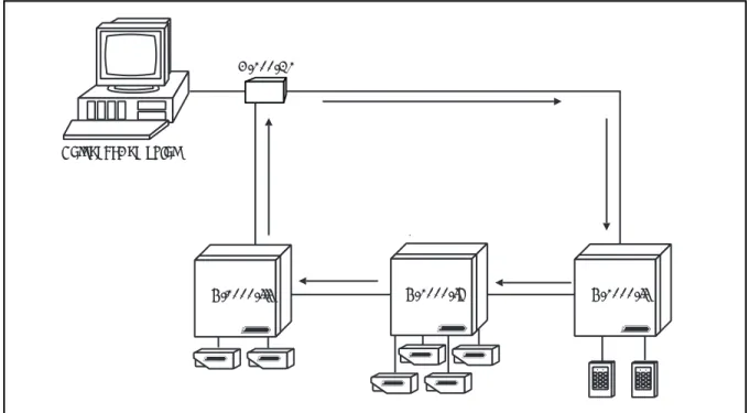
The control panels interface to the programming device via the C-100-A1 20 mA Current Loop Converter or via the 485 multi-drop interfaces
(N-485-PCI-2 or N-485-HUB-2). A single communications loop supports up to 63 uniquely addressed control panels if the 20 mA loop is utilized or 31 panels for 485 communications. A typical 20 mA communications loop configuration is shown in Figure 2-1, while Figure 2-2 illustrates a typical 485 multi-drop
configuration.
The N-1000-III control panel provides 16 points for alarm monitoring and four output control relays. The N-1000-III-X control panel includes four additional relays (providing a total of eight) and has expanded database/buffer memory capacity. The N-1000-IV version has four rather than two card readers and four output control relays. The N-1000-IV-X control panel includes four additional relays (providing a total of eight) with expanded database/buffer memory capacity. The
N-1000-IV N-1000-II
N-1000-III
Personal Computer
C-100-A1
-Figure 2-1. Typical 20 mA Communications Loop. The N-1000 control panels can be in any order in the loop or dropline as long as each has a unique address.
2–2 2–2 2–2 2–2
2–2 N-1000-III/IVN-1000-III/IVN-1000-III/IVN-1000-III/IVN-1000-III/IV Section 2: System OverviewSection 2: System OverviewSection 2: System OverviewSection 2: System OverviewSection 2: System Overview
N-1000-III-X is shown in Figure 2-3 with enclosure and battery. Figure 2-4 shows the N-1000-IV-X with Four Reader Board, battery and enclosure.
The minimum configuration for the N-1000-III/IV includes the control panel, power transformer, reader and communication converter.
Control panels can operate in a buffered mode in which system transactions are stored in transaction buffer memory at the panels rather than transmitted to the programming device. Every transaction (input point change of state, code use) uses one location in buffer memory. The buffered information can later be transmitted to the programming device.
The N-1000-III/IV firmware (version 08.01.29 or later) has a built-in test capability that can be used to check the functioning of most of the circuit board’s hardware. Refer to Appendix C: Troubling Shooting for details.
2-2: Programming Devices
N-1000-III/IV control panels in a communications loop are programmed with a personal computer, printer/programmer or data terminal.
When using a personal computer as the system programming device, the PC software serves as a database manager for the N-1000-III/IV control panels. Information is entered into the PC databases and then downloaded to the control panels. During the download procedure, the PC software converts the database information at the disk level to a series of command strings from the N-1000 instruction set. The commands are then sent to the appropriate control panels. The panels then operate independently from the computer. The advan-tages of using a computer as the system programming device include ease of programming and operation, permanent disk storage of all database
information and extensive report options.
Figure 2-2. Typical 485-Multidrop Configuration. The N-1000-III/IV can be used in
existing N-1000-II/N-800 systems provided the existing panels have version 8.0 or higher
firmware. When the N-1000-II/N-800 is configured for 485 (N-485-API-2) as in this example, the firmware version must match the 485 version in the N-1000-III/IV.
Personal Computer N485-PCI-2 N-1000-II N-1000-IV N-1000-III N-1000-II with N-485-API-2
Section 2: System Overview Section 2: System Overview Section 2: System Overview Section 2: System Overview
Section 2: System Overview N-1000-III/IVN-1000-III/IVN-1000-III/IVN-1000-III/IVN-1000-III/IV 2–3 2–3 2–3 2–3 2–3
Figure 2-3. N-1000-III-X Panel with Enclosure. The N-1000-III control panel provides 16 alarm points for alarm monitoring capability and four relays for output control capability. The N-1000-III-X includes four additional relays (providing a total of eight) and has expanded
database/buffer memory capacity.
Panel must be earth grounded.
S-4 SUPPRESSION REQUIRED ACROSS EVERY ACTIVE RELAY AND ELECTRICAL DEVICE (CONNECT WITHIN 18 INCHES). Lock Solenoid 1 345678910 2 1112
Figure 2-4. N-1000-IV-X Panel with Enclosure. The N-1000-IV supports four card readers and four relays for output control capability. The N-1000-IV-X includes four additional relays with expanded database/buffer memory capacity.
Panel must be earth grounded.
S-4 SUPPRESSION REQUIRED ACROSS EVERY ACTIVE RELAY AND ELECTRICAL DEVICE (CONNECT WITHIN 18 INCHES). Lock Solenoid 1 345678910 2 1112 Shield GND +5v DØ D1 LED Shield GND +5v DØ D1 LED
LED D1 DØ +5v GND Shield LED D1 DØ +5v GND Shield
StatusLED Northern Computers, Inc.
Reader 1 Reader 2 Reader 3 Reader 4 To N-1000
2–4 2–4 2–4 2–4
2–4 N-1000-III/IVN-1000-III/IVN-1000-III/IVN-1000-III/IVN-1000-III/IV Section 2: System OverviewSection 2: System OverviewSection 2: System OverviewSection 2: System OverviewSection 2: System Overview
When using a printer/programmer or data terminal as the system programming device, all command strings are sent manually to the control panels by the operator. Printer/programmer and data terminal programming provide no safeguard against lost database memory at the panel level.
2-3: C-100-A1 Converter
The C-100-A1 Converter serves as the interface between the programming device and the N-1000 control panels. The C-100-A1 allows the programming device, using RS-232 port, to communicate with the control panels in a 20 mA current loop. The C-100-A1 can be configured for use as a C-100-C, C-100-T or C-100-M, determined by the position of six DIP switches on the RS-232
connector. These configurations are used as follows:
• computer to local control panels C-100-C • printer/programmer to local control panels C-100-T • computer to remote control panels via modem C-100-M Refer to the C-100-A1 Manual for further details.
2-4: N-485-PCI-2 or HUB-2
The N-485-PCI-2 is used to interface between a PC’s RS-232 port and the 485 multi-drop communications bus. The N-485-HUB-2 is used to interface between a modem’s RS-232 port and the 485 multi-drop bus. Only the “-2” versions of these products will function with the N-1000-III/IV.
2-5: PROM Versions
The N-1000-III/IV PROM (Programmable Read Only Memory) chips provide permanent storage for the program and control logic information necessary to coordinate and drive the system hardware. The PROM chip is also referred to as the control panel’s FIRMWARE.
The PROM version in use determines the commands and programming features available for use with the control panel. Operations such as alarm point programming, site code checking, card/ keycode capacity, transaction buffer capacity, Visitor and Limited Use status cards and local anti-passback are all functions of the PROM version in use. Specific command string syntax and the availability of advanced programming commands are also dependent upon the PROM version. Refer to the command summary in Appendix A of this manual. Or contact NCI for additional information on PROM versions.
N-1000-III/IV N-1000-III/IVN-1000-III/IV N-1000-III/IV N-1000-III/IV Section 3: Hardware Specifications
Section 3: Hardware Specifications Section 3: Hardware Specifications Section 3: Hardware Specifications
Section 3: Hardware Specifications 3–1 3–1 3–1 3–1 3–1
Section 3: Hardware Specifications
Power Requirements:
The N-1000-III/IV requires a 16.5 VAC, 50 VA, 60 HZ or 12 VDC linear (2 amp continuous) power supply.
Output Power:
12 VDC (10 to 14 volts) 500 mA for readers requiring 12 VDC or motion detector devices (not for use with locking devices). A 5 volt 500 mA output is available for standard 5 VDC reader requirements.
Battery Backup:
The 12 VDC (4 amp/hr.) battery provides up to four hours of full operational backup (depending on the load and the age of the battery). To maintain the maxi-mum back-up time, replace the battery every four years or every two years if operating at higher temperatures.
Battery Current Draw:
Control panel 300 mA 300 mA
Alarm points 5 mA each (x 18) 90 mA
Relays activated 50 mA each (x 8) 400 mA 12 V & readers 500 mA maximum 500 mA 5 V card readers 500 mA maximum 500 mA
Total 1.8 amps maximum 1.79 amps
Memory Backup:
A large value capacitor retains panel memory upon loss of both primary and backup battery power for up to seven days (depending on ambient temperature and the number of RAM ICs).
Fuses:
3 amp solid-state, non-replaceable, automatic resetting. Depending on the overload, and the temperature, it may take up to several minutes for the fuses to reset.
Alarm Input Points:
Input points are provided which can be configured for either normally open or normally closed and either 3 state supervised or unsupervised. Separate non-supervised inputs are provided for an optional external primary power fail indication and the standard enclosure tamper switch.
Relay Output Points:
Four double pole, double throw (DPDT) relay contacts with both normally-open and normally-closed sides, rated for 30 VDC 2 amp inductive loads. The N-1000-III/IV-X controllers provide four additional relays (eight total). These relays can also be utilized in dry circuit applications (e.g. , mechanical shunts, data interruptions, etc.). NOTE: once the relay pole has been used on an inductive load (door strikes, magnetic locks, etc.) it cannot be used in low current dry circuit applications. Northern recommends using the “A” pole of the relays for inductive loads and the “B” pole for dry circuit (logic) loads.
N-1000-III/IV N-1000-III/IVN-1000-III/IV N-1000-III/IVN-1000-III/IV 3–2 3–23–2 3–2
3–2 Section 3: Hardware Specifications Section 3: Hardware Specifications Section 3: Hardware Specifications Section 3: Hardware Specifications Section 3: Hardware Specifications
Operating Temperature:
35º to 110º F ( 2º to 43º C)
Operating Relative Humidity:
Up to 85% non-condensing.
Enclosure:
14" H x 16" W x 4" D (35.6 cm x 40.6 cm x 10.2 cm) with knockouts, hinged cover with lock and key. Enclosure tamper switch provided. The N-1000-III/IV enclosure (with control panel) is illustrated in Figure 3-1.
Weight:
21 pounds (9.5 kg) with enclosure and backup battery.
Figure 3-1. Enclosure for the N-1000-III/IV. The N-1000 enclosure, shown here with the N-1000-IV panel, has a lock and key, knockouts and a tamper switch. A 12 VDC battery is mounted on the door.
Panel must be earth grounded.
S-4 SUPPRESSION REQUIRED ACROSS EVERY ACTIVE RELAY AND ELECTRICAL DEVICE (CONNECT WITHIN 18 INCHES). Lock Solenoid 1 345678910 2 1112 Shield GND +5v DØ D1 LED Shield GND +5v DØ D1 LED
LED D1 DØ +5v GND Shield LED D1 DØ +5v GND Shield
Status LED Northern Computers, Inc.
Reader 1 Reader 2 Reader 3 Reader 4 To N-1000
N-1000-III/IV N-1000-III/IV N-1000-III/IV N-1000-III/IV N-1000-III/IV Section 4: P Section 4: P Section 4: P Section 4: P
Section 4: Panel Lanel Lanel Lanel Layoutanel Layoutayoutayoutayout 4–14–14–14–14–1
INSTALLATION
Section 4: Panel Layout
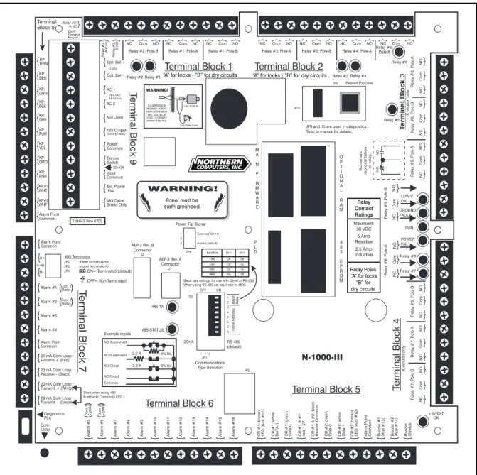
The N-1000-III-X has nine screw-down terminal blocks. Each terminal block, in turn, has 12 individual terminal positions, described in the following sections. Figure 4-1 shows the panel with its printed template. The N-1000-IV-X has an additional board in place of TB5 (see Figure 4-2) with four removable wiring terminal blocks for connection to four readers. Complete terminal block details follow.
Figure 4-1. N-1000-III Panel. The panel is shown with its printed template. N-1000-IV F
N-1000-IV FN-1000-IV F
N-1000-IV F
N-1000-IV Fourourourourour
R
RR
R
N-1000-III/IV N-1000-III/IVN-1000-III/IV N-1000-III/IV N-1000-III/IV 4–2 4–2 4–2 4–2
4–2 Section 4: PSection 4: PSection 4: Panel LSection 4: PSection 4: Panel Lanel Lanel Lanel Layoutayoutayoutayoutayout
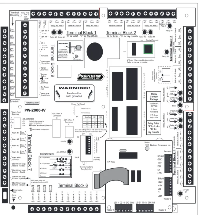
4-1: Four Reader Board (N-1000-IV only)
The N-1000-IV supports up to four card readers. All four readers attach to the panel via a special Four Reader Board mounted in the lower right quadrant of the N-1000-IV panel (see Figure 4-2). The wiring terminals are removable and
interchangeable. The regular reader terminals on the main board are not used. This board is connected to the main panel by connector P3, located directly above the bottom center of the N-1000 panel.
Typical wire color terminations are illustrated in Figure 4-3. Refer to the reader installation technical bulletin (included with the reader) for the most recent color terminations.
Figure 4-2. N-1000-IV Panel. The panel is shown with its printed template and the Four Reader Board..
N-1000-III/IV N-1000-III/IV N-1000-III/IV N-1000-III/IV N-1000-III/IV Section 4: P Section 4: P Section 4: P Section 4: P
Section 4: Panel Lanel Lanel Lanel Layoutanel Layoutayoutayoutayout 4–34–34–34–34–3
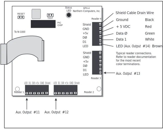
A special, programmable chip, called a PIC chip, controls the Four Reader Board. The PIC chip is labeled with a version number similar to the label on the main panel's PROM chips.
The Four Reader Board has its own Status LED that flashes when it is powered and running. When a card is read the Status LED gives a long flash. When the LED stays on for an extended period of time it indicates that the board has reset due to an error or power supply problem.
A pair of jumper prongs located on the Four Reader Board allows a reader function test. Shorting these prongs (labeled TEST) will cause the board to generate a simulated card read (with the PIC firmware version ) from each of the four readers.
Figure 4-3. Four Reader Board. On the N-1000-IV the Four Reader Board replaces
Terminal Block 5 and provides connections for up to four readers.
LED(Aux. Output #14) Brown Data 1 White Data Ø Green + 5 VDC Red Ground Black Shield Cable Drain Wire
Typical reader connections. Refer to reader documentation for the most recent
color terminations. Shield GND +5v DØ D1 LED Shield GND +5v DØ D1 LED
LED D1 DØ +5v GND Shield LED D1 DØ +5v GND Shield
Status
LED Northern Computers, Inc.
Reader 1 Reader 2 Reader 3 Reader 4 To N-1000 Aux. Output #13 Aux. Output #12 Aux. Output #11
N-1000-III/IV N-1000-III/IVN-1000-III/IV N-1000-III/IV N-1000-III/IV 4–4 4–4 4–4 4–4
4–4 Section 4: PSection 4: PSection 4: Panel LSection 4: PSection 4: Panel Lanel Lanel Lanel Layoutayoutayoutayoutayout
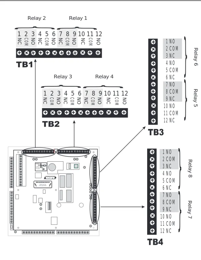
4-2: Terminal Blocks 1, 2, 3, 4
(Terminal Blocks 3 and 4 are available on the N-1000-III/IV-X only) Each DPDT relay provides control for up to two external devices. Both poles of a given relay have a closed terminal, a common terminal and a normally-open terminal. (See Figure 4-4.) Northern recommends using the A pole of the relays for locks (inductive loads) and the B pole for dry circuit (logic) applica-tion.
Terminal Block 1 provides relay contacts for relays 1 and 2. Terminal Block 2 provides relay contacts for relays 3 and 4. Terminal Block 3 provides relay contacts for relays 5 and 6. Terminal Block 4 provides relay contacts for relays 7 and 8. Terminal block 1, 2, 3, 4 terminations are as follow:
Pos. TB1 TB2 TB3 TB4 Function
1 Relay 2: A Relay 3: A Relay 6: A Relay 8: A Normally-Closed 2 Relay 2: A Relay 3: A Relay 6: A Relay 8: A Common
3 Relay 2: A Relay 3: A Relay 6: A Relay 8: A Normally-Open 4 Relay 2: B Relay 3: B Relay 6: B Relay 8: B Normally-Closed 5 Relay 2: B Relay 3: B Relay 6: B Relay 8: B Common
6 Relay 2: B Relay 3: B Relay 6: B Relay 8: B Normally-Open 7 Relay 1: A Relay 4: A Relay 5: A Relay 7: A Normally-Closed 8 Relay 1: A Relay 4: A Relay 5: A Relay 7: A Common
9 Relay 1: A Relay 4: A Relay 5: A Relay 7: A Normally-Open 10 Relay 1: B Relay 4: B Relay 5: B Relay 7: B Normally-Closed 11 Relay 1: B Relay 4: B Relay 5: B Relay 7: B Common
N-1000-III/IV N-1000-III/IV N-1000-III/IV N-1000-III/IV N-1000-III/IV Section 4: P Section 4: P Section 4: P Section 4: P
Section 4: Panel Lanel Lanel Lanel Layoutanel Layoutayoutayoutayout 4–54–54–54–54–5
Figure 4-4. Terminal Blocks 1, 2, 3, 4. Terminal blocks 3 and 4 are available on the X versions of the N-1000-III/IV.
Panel must be earth grounded.
S-4 SUPPRESSION REQUIRED ACROSS EVERY ACTIVE RELAY AND ELECTRICAL DEVICE (CONNECT WITHIN 18 INCHES). Lock Solenoid 1 3 4567 8910 2 1112
}
1 2 3 4 5 6 7 8 9 10 11 12
NC COM NO NC COM NO NC COM NO NC COM NONC
1 2 3 4 5 6 7 8 9 10 11 12
COM NO NC COM NO NC COM NO NC COM NO} }
Relay 2 Relay 1}
Relay 3 Relay 41 NO
2 COM
3 NC
4 NO
5 COM
6 NC
7 NO
8 COM
9 NC
10 NO
11 COM
12 NC
}
Relay 6 Relay 5}
1 NO
2 COM
3 NC
4 NO
5 COM
6 NC
7 NO
8 COM
9 NC
10 NO
11 COM
12 NC
}
Relay 8 Relay 7}
N-1000-III/IV N-1000-III/IVN-1000-III/IV N-1000-III/IV N-1000-III/IV 4–6 4–6 4–6 4–6
4–6 Section 4: PSection 4: PSection 4: Panel LSection 4: PSection 4: Panel Lanel Lanel Lanel Layoutayoutayoutayoutayout
4-3: Terminal Block 5
Terminal Block 5 (N-1000-III only) supports the interface to two Wiegand output card readers and provides an alarm point common. Each card reader port includes terminals for LED control, Data 1 signal, Data Ø signal, +5 VDC output and Ground. Figure 4-5 illustrates typical wire color terminations. Refer to Reader Installation Tech Bulletin (included with the reader) for most recent color terminations. Refer to Section 6 for specific card reader wiring/installation
details.
Terminal Function Reader Wire Color
1 Card Reader 1: LED (Aux. Output 11) Brown
2 Card Reader 1: Data 1 White
3 Card Reader 1: Data Ø Green
4 Card Readers 1 & 2: +5 VDC Red
5 Card Readers 1 & 2: Ground Black
6 Card Reader 2: Data Ø Green
7 Card Reader 2: Data 1 White
8 Card Reader 2: LED (Aux. Output 12) Brown 9 Alarm Point Common*
10 LED/Buzzer 3 (Aux. Output 13) 11 LED/Buzzer 4 (Aux. Output 14)
12 Earth Ground for Cable Shields Shield
*All N-1000 alarm point commons are electrically the same and can be used with any panel alarm point.
4-4: Terminal Block 6
Terminal Block 6 contains alarm input points 5-16 terminals. Any N-1000 alarm common can be used with the alarm inputs. (See Figure 4-5.)
TB6 Terminal Function
1 Alarm Input 5 (Door 1 Egress) 2 Alarm Input 6 (Door 2 Egress)
3 Alarm Input 7 (Door 3 Egress N-1000-IV) 4 Alarm Input 8 (Door 4 Egress N-1000-IV)
5 Alarm Input 9 6 Alarm Input 10 7 Alarm Input 11 8 Alarm Input 12 9 Alarm Input 13 10 Alarm Input 14 11 Alarm Input 15 12 Alarm Input 16
N-1000-III/IV N-1000-III/IV N-1000-III/IV N-1000-III/IV N-1000-III/IV Section 4: P Section 4: P Section 4: P Section 4: P
Section 4: Panel Lanel Lanel Lanel Layoutanel Layoutayoutayoutayout 4–74–74–74–74–7
Figure 4-5. Terminal Block 5 and Terminal Block 6. Terminal Block 5 is only available on the N-1000-III. It supports the interface to two Wiegand output card readers and provides an alarm point common. Terminal Block 6 contains alarm input points 5-16 terminals. Any N-1000 alarm common can be used with the alarm inputs.
Panel must be earth grounded.
S-4 SUPPRESSION REQUIRED ACROSS EVERY ACTIVE RELAY AND ELECTRICAL DEVICE (CONNECT WITHIN 18 INCHES). Lock Solenoid 1 34567 8910 2 1112 12 Alar m Input 16 11 Alar m Input 15 10 Alar m Input 14 9 Alar m Input 13 8 Alar m Input 12 7 Alar m Input 11 6 Alar m Input 10 5 Alar m Input 9 4 Alar
m Input 8 (Door 4 Egress N-1000-IV)
3 Alar
m Input 7 (Door 3 Egress N-1000-IV)
2 Alar
m Input 6 (Door 2 Egress)
1 Alar
m Input 5 (Door 1 Egress)
12 Ear
th Ground for Cable Shields
Shield
11 LED/Buzzer 4 (Aux. Output 14)
10 LED/Buzzer 3 (Aux. Output 13)
9 Alar
m P
oint Common
8 Card R
eader 2: LED (Aux. Output 12)
Brown 7 Card R eader 2: Data 1 White 6 Card R eader 2: Data Ø Green 5 Card R
eaders 1 & 2: Ground
Black 4 Card R eaders 1 & 2: +5 VDC Re d 3 Card R eader 1: Data Ø Green 2 Card R eader 1: Data 1 White 1 Card R
eader 1: LED (Aux. Output 11)
Brown
}
Card Reader 1
}
N-1000-III/IV N-1000-III/IVN-1000-III/IV N-1000-III/IV N-1000-III/IV 4–8 4–8 4–8 4–8
4–8 Section 4: PSection 4: PSection 4: Panel LSection 4: PSection 4: Panel Lanel Lanel Lanel Layoutayoutayoutayoutayout
4-5: Terminal Block 7
Terminal Block 7 contains the 485 multi-drop communication connection, terminals for alarm input points 1 through 4, an alarm point common and the 20 mA com-munication loop (receive and transmit) terminals as illustrated in Figure 4-6. NOTE: The yellow communications LED (CR16) can be enabled when using RS-485 interface by shorting TB7-11 and TB7-12 together.
Jumper settings on the panel are used to select either the 485 multi-drop or the 20 mA communications mode. The last panel on the 485 multi-drop cable must be properly configured. Refer to Section 4-9, Jumpers, for further information. The 20 mA communication protocol specifications are as follow:
ASCII text characters 8 data bits
1 stop bit No parity
(Refer to Section 4-8 for baud rate settings.)
Terminal Function Wire Color(s)
1 Alarm Point Common*
2 485 multi-drop (A+) Red
3 485 multi-drop (B+) Black
4 Alarm Input 1 (Door 1 status) 5 Alarm Input 2 (Door 2 status)
6 Alarm Input 3 (Door 3 status N-1000-IV) 7 Alarm Input 4 (Door 4 status N-1000-IV) 8 Alarm Point Common*
9 20 mA Communication Loop: Receive+ Red
10 20 mA Communication Loop: Receive– Black 11 20 mA Communication Loop: Transmit+ White 12 20 mA Communication Loop: Transmit– Green
*All N-1000 alarm point commons are electrically the same and can be used with any panel alarm points.
N-1000-III/IV N-1000-III/IV N-1000-III/IV N-1000-III/IV N-1000-III/IV Section 4: P Section 4: P Section 4: P Section 4: P
Section 4: Panel Lanel Lanel Lanel Layoutanel Layoutayoutayoutayout 4–94–94–94–94–9
Figure 4-6. Terminal Block 7. Terminal Block 7 contains the 485 multi-drop communication connection terminals for alarm input points 1 through 4, an alarm point common and the 20 mA communication loop (receive and transmit) terminals.
N-1000-III/IV N-1000-III/IVN-1000-III/IV N-1000-III/IV N-1000-III/IV 4–10 4–10 4–10 4–10
4–10 Section 4: PSection 4: PSection 4: Panel LSection 4: PSection 4: Panel Lanel Lanel Lanel Layoutayoutayoutayoutayout
4-6: Terminal Block 8
Terminal Block 8 is used for 11-conductor matrix keypad connections and also provides an alarm point common. (See Figure 4-7.)
Refer to 11-Conductor Keypad instructions (Section 6) for 2 of 7 matrix (row/ column) information. Keypad Use: TB8 Terminal Color/Function 1 Brown (Column 1) 2 Blue (Column 2) 3 Green (Column 3) 4 Black (Common) 5 Gray (Row 1) 6 Purple (Row 2) 7 Yellow (Row 3) 8 Orange (Row 4) 9 Peach/Pink (+5v)
10 Keypad 1: White (Select 1) 11 Keypad 2: White (Select 2) 12 Alarm Point Common*
4-7: Terminal Block 9
Terminal Block 9 is located just to the right of terminal Block 8. It has the power supply and auxiliary connections. See Figure 4-7. The 12 volt back-up battery wires are soldered to the circuit board. When connecting an external DC supply the N-1000-III/IV 12 VDC battery can remain connected and provides additional battery backup.
TB9 Terminal Function
1 Transformer Earth Ground (DO NOT USE if panel is already connected to earth ground. Refer to Section 8-1.)
2 External DC Supply + (12 V battery +) 3 External DC Supply – (12 V battery –) 4 AC Transformer Wire 1
5 AC Transformer Wire 2
6 Not Used
7 +12V DC Output (500 mA - not for Locking Device)
8 DC Common*
9 Tamper Switch Input
10 Input Common*
11 External Power Fail Input 12 485 Shield (if used)
*All N-1000 alarm point commons are electrically the same and can be used with any panel alarm points.
N-1000-III/IV N-1000-III/IV N-1000-III/IV N-1000-III/IV N-1000-III/IV Section 4: P Section 4: P Section 4: P Section 4: P
Section 4: Panel Lanel Lanel Lanel Layoutanel Layoutayoutayoutayout 4–114–114–114–114–11
Figure 4-7. Terminal Blocks 8 & 9. Terminal Block 8 is used for 11-conductor matrix keypad connections and also provides an alarm point common. Terminal Block 9 is located just to the right of Terminal Block 8. It has the power supply and auxiliary connections.
N-1000-III/IV N-1000-III/IVN-1000-III/IV N-1000-III/IV N-1000-III/IV 4–12 4–12 4–12 4–12
4–12 Section 4: PSection 4: PSection 4: Panel LSection 4: PSection 4: Panel Lanel Lanel Lanel Layoutayoutayoutayoutayout
4-8: DIP Switch Settings
N-1000-III/IV DIP switch positions 1 and 2 control the panel baud rate for the 20 mA Loop. Set the panel baud rate to match that of the system programming device. 1200 baud is recommended for computer and data terminal systems. For 485 communications use the 4800 baud setting.
N-1000-III/IV DIP switch positions 3 through 8 determine a control panel’s address. (See Figure 4-8.) Each control panel in the communication loop must have a unique address to allow unique referencing during system programming. When running the panel’s self-test, set all DIP switches to the On position before restarting the panel. (For details of the self-test, refer to Appendix C: Trouble Shooting.)
Baud rate and panel address DIP switch settings are as follow:
Baud Rate 1 2 Panel No. 3 4 5 6 7 8
1200 Off Off 1 On On On On On Off
2400 Off On 2 On On On On Off On
4800 On On 3 On On On On Off Off
9600 On Off 4 On On On Off On On
5 On On On Off On Off
6 On On On Off Off On
7 On On On Off Off Off
8 On On Off On On On
9 On On Off On On Off
10 On On Off On Off On
11 On On Off On Off Off
12 On On Off Off On On
13 On On Off Off On Off
14 On On Off Off Off On
15 On On Off Off Off Off
16 On Off On On On On
17 On Off On On On Off
18 On Off On On Off On
Figure 4-8. DIP Switches.Switch positions 1 and 2 control the panel baud rate for the 20 mA loop; switch positions 3 through 8 determine the control panel’s address. The positions above are set for panel 1 and a baud rate of 2400.
Panel must be earth grounded.
S-4 SUPPRESSION REQUIRED ACROSS EVERY ACTIVE RELAYAND ELECTRICAL DEVICE (CONNECT WITHIN 18 INCHES). Lock Solenoid 1 34 5678910 2 1112 1 2 3 4 5 6 7 8 1 2 3 4 5 6 7 8 ON
}
Baud Rate}
Panel AddressN-1000-III/IV N-1000-III/IV N-1000-III/IV N-1000-III/IV N-1000-III/IV Section 4: P Section 4: P Section 4: P Section 4: P
Section 4: Panel Lanel Lanel Lanel Layoutanel Layoutayoutayoutayout 4–134–134–134–134–13
Panel 3 4 5 6 7 8
19 On Off On On Off Off
20 On Off On Off On On
21 On Off On Off On Off
22 On Off On Off Off On
23 On Off On Off Off Off
24 On Off Off On On On
25 On Off Off On On Off
26 On Off Off On Off On
27 On Off Off On Off Off
28 On Off Off Off On On
29 On Off Off Off On Off
30 On Off Off Off Off On
31 On Off Off Off Off Off
32 Off On On On On On
33 Off On On On On Off
34 Off On On On Off On
35 Off On On On Off Off
36 Off On On Off On On
37 Off On On Off On Off
38 Off On On Off Off On
39 Off On On Off Off Off
40 Off On Off On On On
41 Off On Off On On Off
42 Off On Off On Off On
43 Off On Off On Off Off
44 Off On Off Off On On
45 Off On Off Off On Off
46 Off On Off Off Off On
47 Off On Off Off Off Off
48 Off Off On On On On
49 Off Off On On On Off
50 Off Off On On Off On
51 Off Off On On Off Off
52 Off Off On Off On On
53 Off Off On Off On Off
54 Off Off On Off Off On
55 Off Off On Off Off Off
56 Off Off Off On On On
57 Off Off Off On On Off
58 Off Off Off On Off On
59 Off Off Off On Off Off
60 Off Off Off Off On On
61 Off Off Off Off On Off
62 Off Off Off Off Off On
63 Off Off Off Off Off Off
NOTE: For DIP switches with OPEN/CLOSED notation:
OPEN=Off CLOSED=On
NOTE: The restart button MUST be pressed to activate a change made to any DIP switch setting (for baud rate and/or panel address). Pressing the restart button DOES NOT alter N-1000-III/IV database memory.
NOTE: Addresses 32 and above cannot be used with the 485 multi-drop.
N-1000-III/IV N-1000-III/IVN-1000-III/IV N-1000-III/IV N-1000-III/IV 4–14 4–14 4–14 4–14
4–14 Section 4: PSection 4: PSection 4: Panel LSection 4: PSection 4: Panel Lanel Lanel Lanel Layoutayoutayoutayoutayout
4-9: Jumpers
There are several jumpers on the circuit board (Figure 4-9) which configure the panel for various modes of operation as indicated below:
Number Position Function
JP1 Jump Pins 1 & 2 Select 20 mA communications loop.
Jump Pins 2 & 3 Select 485 multi-drop communications (default).
JP2 Open Provide end of line (EOL) termination for JP3 Open 485 drop line. Refer to Section 6-6-8 for details.
JP4 Jump Pins 1 & 2 Jumper is on for the panel at the end of the 485 multi-drop cable (default).
Remove Remove the jumper if the panel is not at the end of the cable or JP2 and JP3 are used. Refer to
Section 6-6-8 for details.
JP5 (Not Used)
JP6 Jump pins 2 & 3 Select onboard power status detection (default). Jump Pins 1 & 2 Select external power status detection.
JP7 (Not Used)
JP8 (Not Used)
JP9 Jump Pins 1 & 2 Disable clearing of RAM by JP10 (default). Remove Enable clearing the RAM by JP10.
JP10 Jump Pins 1 & 2 Clears RAM when power is off for at least 60 seconds and JP9 is removed.
Remove Will not clear RAM, allows supercap to backup memory (default).
N-1000-III/IV N-1000-III/IV N-1000-III/IV N-1000-III/IV N-1000-III/IV Section 4: P Section 4: P Section 4: P Section 4: P
Section 4: Panel Lanel Lanel Lanel Layoutanel Layoutayoutayoutayout 4–154–154–154–154–15
Figure 4-9. Configuration Jumpers and Connectors. The N-1000-III/IV panels provide for either 485 multi-drop communication or 20 mA communication loops. These modes are selected by changing jumper settings.
4-10: Connectors
Connector Function
Battery Wires Red and Black wires soldered to the circuit board with fast-on connectors for the 12 volt backup battery
J1 Four pin connector for the AEP-3 (Revision A) Relay Expansion Board(s)
J2 Eight pin connector for the AEP-3 (Revision B) Relay Expansion Board(s)
Panel must be earth grounded.
S-4 SUPPRESSION REQUIRED ACROSS EVERY ACTIVE RELAY AND ELECTRICAL DEVICE (CONNECT WITHIN 18 INCHES). Lock Solenoid 1 3 4 5 67 89 10 2 11 12 Jumpers 2, 3 & 4 Jumper 1 Jumper 10 Jumper 9 Jumper 6 Jumpers 5, 7, 8, and 11 are not used. Battery Wires with
fast-on connectors J2 AEP-3 Rev. B Connector J1 AEP-3 Rev. A Connector
N-1000-III/IV
N-1000-III/IV N-1000-III/IVN-1000-III/IV N-1000-III/IV N-1000-III/IV 4–16 4–16 4–16 4–16
4–16 Section 4: PSection 4: PSection 4: Panel LSection 4: PSection 4: Panel Lanel Lanel Lanel Layoutayoutayoutayoutayout
4-11: LEDs
The functions of the N-1000-III/IV LEDs are listed below and also illustrated in Figure 4-10. When an LED is lit it indicates that its relay is energized, that is the normally open relay contacts become closed and the normally closed relay contacts become open. Not lit indicates relay is de-energized, that is normally open and normally closed contacts are in normal state.
Function LED Color Lit Indicates
Output Relay 1 Indicator: 1 Red Energized Output Relay 2 Indicator: 2 Red Energized Output Relay 3 Indicator: 3 Red Energized Output Relay 4 Indicator: 4 Red Energized Output Relay 5 Indicator: 5 Red Energized Output Relay 6 Indicator: 6 Red Energized Output Relay 7 Indicator: 7 Red Energized Output Relay 8 Indicator: 8 Red Energized
485 Status: 9 Green Slow flashing indicates proper 485 communications
+12 VDC Indicator: 10 Green 12 V DC external power is available +5 VDC Indicator: 11 Green Panel is supplying +5 VDC output for
reader/keypad power
Low-Voltage OK: 12 Green Battery voltage acceptable and RAM back-up available
Input Ground: 13 Red Ground fault detected
Run: 14 Green Pulsing indicates N-1000 microprocessor operating properly (not lit or not pulsing indicates malfunction) Power Status: 15 Red Loss of primary power with panel
powered by 12 VDC battery (fast flashing indicates battery charge is too low to operate panel even with
primary power available)
Com Loop Indicator: 16 Yellow Loop current is present (flashing off indicates data flow)
485-TX: 17 Red Periodic quick flashing indicates 485 communications link functioning properly
Four Reader Board Status Green Quick flash indicates processor running, long flash indicates card read, very long flash indicates reset due to error or power problem
N-1000-III/IV N-1000-III/IV N-1000-III/IV N-1000-III/IV N-1000-III/IV Section 4: P Section 4: P Section 4: P Section 4: P
Section 4: Panel Lanel Lanel Lanel Layoutanel Layoutayoutayoutayout 4–174–174–174–174–17
Figure 4-10. LED Functions.When an LED is lit it indicates that its relay is energized, that is, the normally open relay contacts become closed and the normally closed relay contacts become open. Not lit indicates relay is de-energized, that is normally open and normally closed contacts are in normal state.
N-1000-III/IV N-1000-III/IVN-1000-III/IV N-1000-III/IV N-1000-III/IV 4–18 4–18 4–18 4–18
4–18 Section 4: PSection 4: PSection 4: Panel LSection 4: PSection 4: Panel Lanel Lanel Lanel Layoutayoutayoutayoutayout
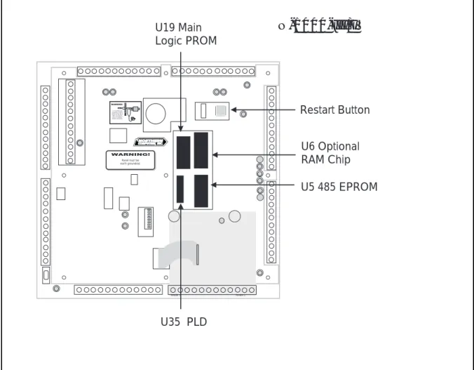
4-12: Restart Button
The restart button is used to restart the N-1000-III/IV microprocessor. (See Figure 4-11.) Press the restart button to restart a “locked-up” control panel and to activate a change made to any DIP switch setting (for baud rate and/or panel address). The panel’s self-test feature can be activated by setting all of the DIP switches to the On position and then depressing the Restart button. For details of the self-test, refer to Appendix C: Troubling Shooting.
Pressing the Restart button DOES NOT alter N-1000-III/IV database memory. The data base can be completely cleared by the following method: Disconnect the AC power and battery back-up. Move jumper JP9 to position JP10 for one minute then return it to JP9. Restore the power connections.
4-13: RAM Chip
Control panel RAM chips store all database and transaction buffer memory. The N-1000-III/IV control panels use a single RAM chip with the option of an addi-tional chip in socket U6. The N-1000-III/IV-X control panels come equipped with an extra RAM chip. (See Figure 4-11.)
NOTE: Control panel card database and transaction buffer capacities are deter-mined by the number of RAM chips used and can be modified by use of the U command I option. Refer to Appendix A: Programming Quick Reference Guide for details.
4-14: PROM Chip
The control panel PROM chips store all N-1000-III/IV program and control logic memory and are located in sockets U5 & U19. (See Figure 4-11.) On each PROM is a sticker which indicates the socket number and the firmware version of the chip. Refer to the main PROM number when referencing the N-1000-III/IV Programming Manual for specific programming/operation functions.
4-15: Additional Installation Information
Northern Computers recommends the following installation techniques for the N-1000 panels:
DO
• Do run all wiring for door locks/strikes and panel primary power in a
sepa-rate conduit or allow at least 12 inches of space between the power cables and the data/reader cables.
• Do use shielded cables or metal conduit when necessary to reduce interfering radio frequency emissions.
N-1000-III/IV N-1000-III/IV N-1000-III/IV N-1000-III/IV N-1000-III/IV Section 4: P Section 4: P Section 4: P Section 4: P
Section 4: Panel Lanel Lanel Lanel Layoutanel Layoutayoutayoutayout 4–194–194–194–194–19
Figure 4-11. Additional Panel Features. The restart button is used to restart the
N-1000-III/IV microprocessor. It can be used to restart a “locked-up” control panel or to activate a change made to any DIP switch setting (for baud rate and/or panel address). The N-1000-III/ IV-X control panel comes equipped with an additional RAM chip, located in socket U6. The control panel PROM chips, located in sockets U5 & U19, store all N-1000-III/IV program and control logic memory.
Panel must be earth grounded.
S-4 SUPPRESSION REQUIRED ACROSS EVERY ACTIVE RELAY AND ELECTRICAL DEVICE (CONNECT WITHIN 18 INCHES). LLoocckk SSoolleennooiidd 11 3344 5566 7788 991010 22 11111212
N-1000-III/IV
Reader 1 Reader 2 Restart Button U6 Optional RAM Chip U19 Main Logic PROM U35 PLD U5 485 EPROM• Do not mount the power supplies, modem, or external relays inside the panel
enclosure. An empty enclosure (ENC-0 or ENC-2) is available for this purpose. It is the same size as the N-1000 enclosure, with the same locking mechanism.
• Do not “string” wire across the face of the panel.
• Do not use the same power supply for both locks and control panel or locks
and readers.
• Do not mount the control panel in or near an area that has electric noise
N-1000-III/IV N-1000-III/IVN-1000-III/IV N-1000-III/IV N-1000-III/IV 4–20 4–20 4–20 4–20
4–20 Section 4: PSection 4: PSection 4: Panel LSection 4: PSection 4: Panel Lanel Lanel Lanel Layoutayoutayoutayoutayout
Panel must be earth grounded.
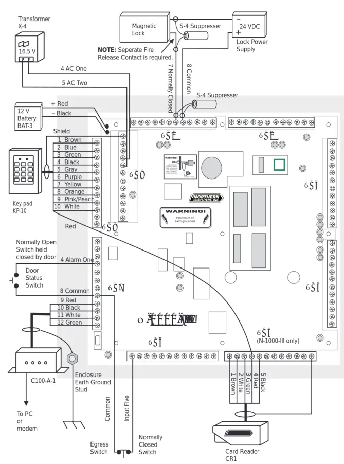
S-4 SUPPRESSION REQUIRED ACROSS EVERY ACTIVE RELAY AND ELECTRICAL DEVICE (CONNECT WITHIN 18 INCHES). 1 Brown 2 Blue 3 Green 4 Black 5 Gray 6 Purple 7 Yellow 8 Orange 9 Pink/Peach 10 White 9 Red 10 Black 11 White 12 Green 5 Bl ack 4 Red 3 G reen 2 W hit e 1 Br ow n TB1 TB7 TB8 TB9
N-1000-III
Magnetic Lock Key pad KP-10 12 V Battery BAT-3 C100-A-1 Transformer X-4 4 AC One 5 AC Two Normally Open Switch heldclosed by door 4 Alarm One
24 VDC Lock Power Supply – + 7 N orm al ly Cl osed 8 Co mmo n Enclosure Earth Ground Stud To PC or modem + Red – Black Shield TB6 TB2 TB3 TB4 TB5 (N-1000-III only) Red Door Status Switch Card Reader CR1 Egress Switch Normally Closed Switch S-4 Suppresser
NOTE: Seperate Fire
Release Contact is required. 16.5 V 8 Common In pu t F iv e Co mmo n S-4 Suppresser
Figure 4-12. Example Wiring Diagram.Card Readers connect to TB5 of the N-1000-III as shown here. On the N-1000-IV, the card readers connect to the Four Reader Board. Refer to
Section 5: Operation Section 5: Operation Section 5: Operation Section 5: Operation
Section 5: Operation N-1000-III/IV N-1000-III/IV N-1000-III/IV N-1000-III/IV N-1000-III/IV 5–15–15–15–15–1
Section 5: Operation
5-1: Card Reader/Keypad Operation
Some card readers require that a format (software) command be programmed into the host N-1000-III/IV controller before cards can be read. If the format command is not programmed into the control panel, these readers or keypads will not trans-mit card numbers to the terminal/printer. Refer to Appendix A: Programming Quick
Reference Guide for complete F Command format listings.
Verify card reader/keypad operation before programming. Codes need not be programmed into memory to verify reader/keypad operation. When a code is entered or a card presented, it should appear on the display/printer, followed by an NF or not found message.
The control panel continuously monitors the card reader and keypad ports for code use. Access is restricted by placing time zone limitations on the codes in use, NOT by time zone controlling (disabling) the reading devices.
Card reader or keypad activation of output points is determined by the presence or absence of the anti-passback option in panel memory. Refer to I Command, A Option in Appendix A for further information.
In anti-passback configurations with two card readers or two keypads, both devices activate Output Relay 1 (Door 1) upon valid code use (Figure 5-1). In anti-passback applications requiring a separate output relay for the reader (such as turnstile applications), refer to A Command in Appendix A.
In configurations WITHOUT anti-passback enabled, Card Reader or Keypad 1 activates Output Relay 1 (Door 1) and Card Reader or Keypad 2 activates Output Relay 2 (Door 2) (Figure 5-2).
Card readers and keypads can be reassigned to activate a specified input point, output point or group (multiple outputs) upon valid code use, via the
5–2 5–2 5–2 5–2
5–2 N-1000-III/IVN-1000-III/IVN-1000-III/IVN-1000-III/IVN-1000-III/IV Section 5: OperationSection 5: OperationSection 5: OperationSection 5: OperationSection 5: Operation
Figure 5-1. Anti-passback with Two and Four Card Readers. (Keypads may be substituted for card readers on TB8). In anti-passback configurations with two card readers, both devices activate Output Relay 1 (Door 1) upon valid code use. With four card readers, readers 1 and 2 activate Output Relay 1 (Door 1); reader 3 and 4 activate Output Relay 3 (Door 2). In anti-passback applications requiring a separate output relay for each reader (such as turnstile applications) refer to Appendix A, A Command.
WARNING! K3 K4 K 1K 1 K5 K10 K6 K7 K8 K2
N-1000-III
Card Reader 2 – Out
Common
Card Reader 1 – In
Input 1
Door Status Switch
K3K3 K4 K1K1 K5 K10 K6 K2K2 Reader 1 Reader 1 To N-1000 To N-1000 K3 K1 Reader 1 In Reader 3 In
N-1000-IV
Input 1 Input 3 Door 2 Door 1 Reader 2 Out Reader 4 Out Door Status Switch Door Status Switch Door 1Section 5: Operation Section 5: Operation Section 5: Operation Section 5: Operation
Section 5: Operation N-1000-III/IV N-1000-III/IV N-1000-III/IV N-1000-III/IV N-1000-III/IV 5–35–35–35–35–3
Figure 5-2. Two and Four Card Readers without Anti-passback. In configurations WITHOUT anti-passback enabled, card reader 1 activates Output Relay 1 (Door 1) and card reader or keypad 2 activates Output Relay 2 (Door 2). With four readers, card readers 1, 2, 3, and 4 activate output relays 1, 2, 3, and 4 activating doors 1, 2, 3, and 4 respectively.
Lock Solenoid 3 4567 910 2 12 K 1K 1
N-1000-III
K 2K 2 Door 2 Card Reader 2 Door 1 Card Reader 1 Input 1 Point Common Input P oint 2 Panel must be earth grounded. Panel must be earth grounded. S-4 SUPPRESSION REQUIRED ACROSS EVERY ACTIVE RELAY AND ELECTRICAL DEVICE (CONNECT WITHIN 18 INCHES). S-4 SUPPRESSION REQUIRED ACROSS EVERY ACTIVE RELAY AND ELECTRICAL DEVICE (CONNECT WITHIN 18 INCHES). Lock Solenoid 1 345678910 2 1112 Shield GND +5v DØ D1 LED Shield GND +5v DØ D1 LED Shield GND +5v DØ D1 LED Shield GND +5v DØ D1 LED LED D1 DØ +5v GND Shield LED D1 DØ +5v GND Shield LED D1 DØ +5v GND ShieldLED D1 DØ +5v GND ShieldStatus LED Status LED Northern Computers, Inc.Northern Computers, Inc.
Reader 1 Reader 1 Reader 2Reader 2
Reader 3 Reader 3 Reader 4 Reader 4 To N-1000 To N-1000
N-1000-IV
Door 2K3
K1
Door 1 Reader 1 Reader 2 Reader 3 Reader 4 K1 K2K2
K3 K4K4
Door 4 Door 3 Door Status Switch Door Status SwitchDoor Status Switch
Door Status Switch Door Status Switch
5–4 5–4 5–4 5–4
5–4 N-1000-III/IVN-1000-III/IVN-1000-III/IVN-1000-III/IVN-1000-III/IV Section 5: OperationSection 5: OperationSection 5: OperationSection 5: OperationSection 5: Operation
5-2: Alarm Input Points
All N-1000 alarm input points default to normally-closed, non-supervised circuits used to monitor changes of state. N-1000-III/IV inputs can also be configured for normally-open circuits and 3-state supervised circuits. Input points have both a physical state and a software state, as described below:
Physical State
Input points have physical states of OPEN and CLOSED. An open input is considered to be in ALARM condition. A closed input is considered to be in NORMAL
condition.
Software State
Input points have software states of UNSHUNTED (active) and SHUNTED (not active). When an input is unshunted, all physical changes of state (openings and closures) are recognized. When an input is shunted, physical changes of state are
Figure 5-3. Input Point configuration.
N-1000-III/IV Input Configurations
Input Condition Input Status
1. Non-Supervised Normally Closed Circuit (default)
Shorted Normal
Open Alarm
Resistance* Trouble
2. Non-Supervised Normally Open Circuit
Shorted Alarm
Open Normal
Resistance* Trouble
3. 3-State Supervised Normally Closed Circuit
Shorted Trouble
Open Alarm
Resistance Normal
4. 3-State Supervised Normally Open Circuit
Shorted Alarm
Open Trouble
Resistance Normal Normally open circuit
Normally closed circuit Normally open circuit input common input common input common
Normally closed circuit input
common
2.2 K ohm 5% 2.2 K ohm 5%
Section 5: Operation Section 5: Operation Section 5: Operation Section 5: Operation
Section 5: Operation N-1000-III/IV N-1000-III/IV N-1000-III/IV N-1000-III/IV N-1000-III/IV 5–55–55–55–55–5
not recognized. Input shunting is software controlled and does not involve a physical change of state of the input.
The default software state of all input points is unshunted. No programming is necessary to keep inputs in the default state. Programming is only necessary to shunt input points.
Input Points are assigned both shunt time and time zone parameters, as described below:
Shunt Time
The shunt time parameter defines the amount of time the input point is shunted (deactivated) when triggered, such as upon valid code use.
Time Zone
The time zone parameter defines the time the input point is automatically shunted (deactivated).
5-3: Relay Output Points
All N-1000-III/IV relay output points have both open and normally-closed contacts, used to switch (activate/deactivate) electrical devices. Output points have only a physical state, as described below:
Physical State
Output points have physical states of DE-ENERGIZED and ENERGIZED. When an output is de-energized, normally-open and normally-closed contacts are in normal state. When an output is energized, normally-open contacts become closed and normally-closed contacts become open.
The default state of all output points is de-energized. No programming is necessary to keep outputs in the default state. Programming is only necessary to energize output points.
Door locks MUST be wired such that the following conditions are met: 1. DE-ENERGIZED relay outputs (default state ) result in LOCKED doors. 2. ENERGIZED relay outputs result in UNLOCKED doors.
NOTE: The appropriate side of the relay contact (open or
normally-closed) MUST be used to satisfy the conditions stated.
Output points are assigned both pulse time and time zone parameters, as described below:
Pulse Time
The pulse time parameter defines the amount of time the output point is energized when triggered, such as upon valid code use.
5–6 5–6 5–6 5–6
5–6 N-1000-III/IVN-1000-III/IVN-1000-III/IVN-1000-III/IVN-1000-III/IV Section 5: OperationSection 5: OperationSection 5: OperationSection 5: OperationSection 5: Operation
Time Zone
The time zone parameter defines the time the output is automatically energized. Outputs 11 & 12 control Card Reader 1 and Card Reader 2 LEDs, respectively. On the N-1000-IV panel, outputs 13 & 14 control Card Reader 3 and Card Reader 4 LEDs, respectively. Card reader LEDs change state upon valid code use for the duration of the programmed pulse time. Default pulse time for LED outputs is two seconds. Refer to Appendix A, I Command, M Option and V Command for further card reader LED information.
5-4: Default Input Point/Output Point Interaction
The actions of all input points and output points are independent of one another, unless otherwise programmed. Selected inputs and outputs can be programmed to interact with one another through an interlocking option (refer to Appendix A, P Command as well as I Command, E Option). Interlocking allows an input point or output point to take a specified action, based upon another input point or output point change of state.
The reserved input and output points, default interlocks, default pulse times and default shunt times for various system configurations (without anti-passback, with anti-passback and with free egress) are shown below:
Configurations WITHOUT Anti-Passback
Input Point Reserved for: Default shunt time
Input 1 Door position switch for Door 1 15 seconds Input 2 Door position switch for Door 2 15 seconds Input 3* Door position switch for door 3 15 seconds Input 4* Door position switch for door 4 15 seconds
Output Point Reserved for: Default pulse time
Output 1 Door lock for Door 1 10 seconds Output 2 Door lock for Door 2 10 seconds Output 3* Door lock for door 3 10 seconds Output 4* Door lock for door 4 10 seconds
Output 11 Reader 1 LED 2 seconds
Output 12 Reader 2 LED 2 seconds
Output 13* Reader 3 LED 2 seconds
Output 14* Reader 4 LED 2 seconds
*N-1000-IV only
Output 1 is interlocked to Input 1. An activation of Output 1 (such as upon valid code use at card reader/keypad 1) causes Input 1 to be shunted for the duration of its shunt time.
Similarly, outputs 2, 3 and 4 are interlocked to inputs 2, 3 and 4 respectively. Activation of an interlocked output causes the respective interlocked input to be shunted for the duration of its shunt time. (See Figure 5-4.)
Section 5: Operation Section 5: Operation Section 5: Operation Section 5: Operation
Section 5: Operation N-1000-III/IV N-1000-III/IV N-1000-III/IV N-1000-III/IV N-1000-III/IV 5–75–75–75–75–7
Figures 5-4. Interlocked Input/Output on Doors Without Anti-passback.
Example: Valid code use at card reader (or keypad) 1 triggers the pulse time of Output Relay 1,
unlocking Door 1 for 10 seconds and pulsing the reader LED for 2 seconds.
The activation of Output 1 triggers the shunt time of Input 1 (via interlock) shunting Door 1 status switch for 15 seconds.
Lock Solenoid 3456 7 910 2 12 K 1K 1
N-1000-III
K 2K 2 Door 2 Card Reader 2 Door 1 Card Reader 1 Input P oint 1 Common Input P oint 2 Lock Solenoid 1 345678910 2 1112 Shield GND +5v DØ D1 LED Shield GND +5v DØ D1 LED Shield GND +5v DØ D1 LED Shield GND +5v DØ D1 LED LED D1 DØ +5v GND Shield LED D1 DØ +5v GND Shield LED D1 DØ +5v GND ShieldLED D1 DØ +5v GND ShieldStatus LED Status LED Northern Computers, Inc.Northern Computers, Inc.
Reader 1 Reader 1 Reader 2Reader 2
Reader 3 Reader 3 Reader 4 Reader 4 To N-1000 To N-1000
N-1000-IV
Door 2K3
K1
K1
Door 1 Reader 1 Reader 2 Reader 3 Reader 4 K1 K2K2
K3K4
K4 Door 4 Door 3 Output Point (Relay) 1 Pulse Time = 10 seconds Output Point (Relay) 2 Pulse Time = 10 secondsOutput (LED) Pulse
Time = 2 seconds Output (LED) PulseTime = 2 seconds Shunt Time = 15 sec. Shunt Time = 15 sec. Door Status Switch Door Status Switch Output (LED) Pulse Time = 2 sec. Output (LED) Pulse Time = 2 sec.
5–8 5–8 5–8 5–8
5–8 N-1000-III/IVN-1000-III/IVN-1000-III/IVN-1000-III/IVN-1000-III/IV Section 5: OperationSection 5: OperationSection 5: OperationSection 5: OperationSection 5: Operation
Configurations WITH Anti-Passback:
Input Point Reserved for: Shunt Time
Input 1 Door position switch for Door 1 15 seconds Input 3* Door position switch for Door 2 15 seconds
Output Point Reserved for: Pulse Time
Output 1 Door lock for Door 1 10 seconds
Output 3* Door lock for Door 2 10 seconds
Output 1 is interlocked to Input 1. Activation of Output 1 causes Input 1 to be shunted for the duration of its shunt time.
Similarly, on the N-1000-IV only, Output 3 is interlocked to Input 3. Activation of Output 3 causes Input 3 to be shunted for the duration of its shunt time. (See Figure 5-5.)
Configurations With Free Egress:
Input Point Reserved for: Default shunt time
Input 1 Door position switch for Door 1 15 seconds Input 2 Door position switch for Door 2 15 seconds Input 3* Door position switch for Door 3 15 seconds Input 4* Door position switch for Door 4 15 seconds Input 5 Egress device for Door 1 0 seconds (N/A) Input 6 Egress device for Door 2 0 seconds (N/A) Input 7* Egress device for Door 3 0 seconds (N/A) Input 8* Egress device for Door 4 0 seconds (N/A)
Output Point Reserved for: Default pulse time
Output 1 Door lock for Door 1 10 seconds Output 2 Door lock for Door 2 10 seconds Output 3* Door lock for Door 3 10 seconds Output 4* Door lock for Door 4 10 seconds
Input 5 is interlocked to Output 1. An activation of Input 5 (via egress attempt) causes Output 1 to energize for the duration of its pulse time.
Input 6 is interlocked to Output 2. An activation of Input 6 (via egress attempt) causes Output 2 to energize for the duration of its pulse time.
Output 1 is interlocked to Input 1. An activation of Output 1 (such as upon valid code use at card reader/keypad 1 or egress attempt) causes Input 1 to be
shunted for the duration of its shunt time.
Output 2 is interlocked to Input 2. An activation of Output 2 (such as upon valid code use at Card Reader/Keypad 2 or egress attempt) causes Input 2 to be shunted for the duration of its shunt time. (See Figure 5-6.)