Real-time Mesh Extraction of Dynamic Volume Data Using
GPU
Szymon Engel AGH, Krakow, Poland [email protected]
Witold Alda AGH, Krakow, Poland
Krzysztof Boryczko AGH, Krakow, Poland [email protected]
ABSTRACT
In the paper an algorithm of triangle mesh generation for a full three-dimensional volumetric data is presented. Calculations are performed in real time using graphics processors. The method is very well suited for the visu-alization of dynamic data, as the calculations use only the current frame data (not including data from previous frames). Due to high performance of the algorithm, it can be practically applied in programs for digital sculpting, simulators and games which require editable geometries.
Keywords
mesh generation, iso-surface, volume data, real-time, GPU computation
1
INTRODUCTION
Nowadays, visualization of volumetric data is very of-ten applied in practice. Both in medicine, e.g. for the MRI, PET, or CT data presentation in medical imag-ing, nondestructive inspection of materials (industrial CT), digital sculpting software, as well as in computer games. Often the visualization itself is not sufficient and a three-dimensional mesh is required for a physi-cal physi-calculations, such as collision detection, physi-calculation of material properties or stress. Moreover, the advan-tage of representing models with triangle meshes is that modern GPUs are optimized for efficient rendering of triangles.
Another issue is that volumetric data can change dy-namically. When modeling is performed in a program for sculpting a virtual material, a three-dimensional mesh generated in real time is needed in order to dis-play the results. In video games or simulators of earth-moving machineries, we have to deal with the terrain, which cannot be fully represented by height maps. We may require a visualization of structures such as tun-nels, caves, overhangs of the land as well as other mod-ifications caused as a result of a player actions, such as explosions, vehicle interactions with the terrain or other gameplay activities.
Currently available methods often do not allow to gen-erate a mesh for a large amount of data in real time.
Permission to make digital or hard copies of all or part of this work for personal or classroom use is granted without fee provided that copies are not made or distributed for profit or commercial advantage and that copies bear this notice and the full citation on the first page. To copy otherwise, or re-publish, to post on servers or to redistribute to lists, requires prior specific permission and/or a fee.
Sometimes the resulting effect is described as "interac-tive" which usually means ability to carry out calcu-lations giving a few frames per second. This speed, however, is not sufficient for the smooth operation of applications such as computer games.
In response to these problems, a mesh generation al-gorithm for a fully three-dimensional volumetric data has been developed. All calculations are performed on GPU in real time by which we understand the actual mean speed of computations above 30 frames per sec-ond. Another advantage of the presented algorithm is its independence of the volumetric data representation; therefore, scalar fields, implicit functions, or metaball objects can be used.
The rest of this article is organized as follows. The next section presents previous work on mesh generation methods of volumetric data. The third part briefly de-scribes the possible methods of data representation. It then shows the subsequent steps of the algorithm while in the following passage detailed information on how to implement the algorithm using graphics processors is included. The last section presents a description and summary of results.
2
RELATED WORK
The subject of this paper is to visualize an iso-surface generated for the volumetric data using triangle mesh. Mesh-based methods allow their easy integration with other algorithms or modules, e.g. physics engines, that require mesh as an input. Thanks to this approach our algorithm can be used in real-time applications. Therefore, discussion of previous works does not include ray-tracing and view-dependent visualization; however, information on the methods of these types can be found e.g. in [OBA05, LK10, GDL+02].
GPU-based methods which allows to interactive or real-time calculations were presented e.g. in [KOKK06, CNLE09, KOR08, TSD07].
One of the basic methods of generating a mesh on the basis of volumetric data is the Marching Cubes algo-rithm [LC87] developed in the 1980s. It consists in di-viding the visualized space into equal cubes and gen-erating a polygon within each cube, which is then sub-jected to triangulation. The position and shape of the polygon are dependent on the values of an implicit function in eight vertices of each cube. A common issue with this method is that it requires generating a mesh in the entire space of visualized data. In response to this, several hierarchical and adaptive versions of the Marching Cubes algorithm have been developed [OR97, Blo88, WKE99, KKDH07] using octal trees to reduce the area for which calculations were carried out and which reduce the number of triangles by generating them in different densities depending on the distance of the camera. Implementations of of the Marching Cubes algorithm using GPUs are presented in [JC06, Gei07]. Another, possibly less popular, method is the Sur-faceNets method [Gib98] which originally was used to visualize binary medical data. This method is dual to the marching cubes algorithm and, as in the latter one, visualized space is divided into cubes of the same dimensions. In its base version, the method consisted of selecting the nodes belonging to the surface in a way that a certain node has been selected, if among the eight vertices of the cube were those that had a different sign. These nodes were linked with adjacent ones thus creating a net, which was then smoothed by moving the nodes so as to minimize the energy between them while maintaining the restriction that a node could not leave the cube, to which it originally belonged. The final step was a triangulation of the network, which gave the resulting mesh of triangles. The next method which belongs to the group of "dual algorithms" is the one by [Nie04], which generates a mesh very similar to SurfaceNets, but its implementation is more like the Marching Cubes algorithm. One of the important differences between this method and the SurfaceNets is that the mesh generated by the former is a proper two-dimensional manifold.
In addition to the methods outlined above, there are also: the marching tetrahedra method [TPG99], whose operating principle is based on the marching cubes al-gorithm, the marching triangles method based on the Delaunay triangulation [HSIW96] which generates an irregular mesh, or the method based on marching cubes which allows one to obtain sharp edges, described in the work [JLSW02].
We follow the existing approach of dual marching cubes, however, our algorithm is implemented exclu-sively on GPU and it efficiently exploits geometry
shaders. Thanks to the use of dual methods, the result-ing mesh contains fewer triangles and is regular due to the number of generated triangles within each of the cubes. The latter allows the method to be implemented in a very efficient way using graphics processors. Former GPU-accelerated mesh extraction algorithms (e.g. [KW05], [Goe05], [JC06]) are based on both CPU and GPU computations, using vertex or fragment shaders only. Although meshes generated using our method are not proper two-dimensional manifolds, our approach is extremely efficient and can be used for dynamic data which change on random every frame.
3
VOLUMETRIC DATA
The basic method of describing three-dimensional vol-umetric data is the implicit function. By setting the val-ues of the contour we obtain surface limiting the de-sired area. If the values of this function represent the Euclidean distances from a given contour and we save them as an array, then we get a three dimensional signed distance fieldD:R3→R, representing the iso-surface S, defined for pointp∈R3as:
D(p) =sgn(p)·min{|p−q|:q∈S}, (1) where
sgn(p) = {
−1 if p is inside
+1 if p is outside (2) This representation can be stored in graphics card mem-ory as a three-dimensional texture. Thanks to this rep-resentation, smoothing of the resulting mesh using nor-mals computed directly from distance fields and vertex distances from the surface, is very effective.
Also, most medical data is stored in the form of three-dimensional arrays. For such data combined with con-tour values we can generate a mesh. Another, less common way to represent the volumetric data, is using metaball objects which, with adequate representation, can be converted to distance fields.
4
ALGORITHM OVERVIEW
Due to the GPU architecture and the way they carry out calculations, the developed algorithm is based on dual methods. They allow to obtain a regular mesh consist-ing of squares, so one doesn’t need expensive triangula-tion of polygons generated inside a cube, as is the case of marching cubes method. The algorithm has been adapted to carry out calculations on GPUs, and highly parallelized, which allows it to achieve very high per-formance.
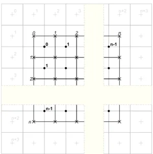
Input data block, of size n3, where nof a form 2k, is divided into equal cubes. This is shown in Figure 1.
0 1 2 n
1
2
n
0 1 n-1
1
n-1
0 1 2 3 n+2 n+3
1
2
3
n+2
n+3
Figure 1: Data organization (2D view) The image represents a two-dimensional version, but the three-dimensional one is similar.
Calculation points marked with "•" symbol are placed in the centers of cubes and their coordinates are used to calculate the distance from the contour, based on the volumetric data. Distance field values are stored in points marked "+", while points marked "×" represent vertices of quadrangles generated by the algorithm. The calculations of the algorithm are processed in two steps. At the beginning, for each calculation point p ∈R3, marked with the symbol "•", such that p∈ {[0,n−1]×[0,n−1]×[0,n−1]}, there are gener-ated three pointsq,r,s∈R3such that forp= (x,y,z):
q= (x−1,y,z), r= (x,y−1,z), s= (x,y,z−1). In
each of these points p,q,r,san implicit function value
dp=f(p)is calculated and three edges defined by pairs of calculation points pq, pr, psare created. Then, for each edge – if its endpoints have different signs (lie on different sides of the contour) – a quadrangle located on the border of the cubes is generated. Its orientation is determined by the direction of the edge, which is con-sistent with the direction of the normal to the surface of the quadrangle. A set of squares, generated in this way, approximates the iso-surface for input volumetric data, and is smoothed in the next stage. As a result of con-version of each square to a pair of triangles, a triangle mesh is obtained.
Due to the fact that during the calculation the sign changes, zero is treated differently depending on the direction of the edge, the condition 3, under which quadrilaterals are generated is presented as follows:
(f(q)≥0∧f(p)<0)∨(f(q)<0∧f(p)≥0) (3) The first step in the algorithm, described above, is ide-ally suited for parallelization, because the calculations
for computing the individual points can be carried out independently. Despite the fact that the distance fields are calculated for each point twice, it is possible to ob-tain a high-performance computing algorithm, because it is not a costly operation.
The second stage of the algorithm is a smoothing of generated mesh by moving its vertices in the direction of the surface represented by the distance fields values. For this purpose, at each vertex of the distance field, a normal vectornis calculated on the basis of the gradi-ent and the distanced to the surface. Then, the vertex is moved in the direction of the normal, by the value calculated according to formula 4.
p′=p+dn (4)
In the case that the resulting mesh is used only for dis-playing a surface, this step can be implemented directly during rendering. Otherwise, it is possible to smooth the mesh only and use it for subsequent calculations, such as collision detection.
The advantage of the developed algorithm over march-ing cubes method consists partly in that for creatmarch-ing a quad for the cube we generate exactly four indices and there is no need for triangulation of polygons gener-ated. This allows the calculations to be successfully performed on the GPU.
5
IMPLEMENTATION DETAILS
The algorithm was implemented using the OpenGL graphics library; however, DirectX library can be used as well.
Input volumetric data, for which a mesh is generated, is divided into equal blocks, for which fragments of the mesh are generated independently. This approach was chosen because of the GPU hardware limitations on the maximum size of supported textures, as well as for op-timization purposes. To be specific: not all parts of dy-namic data need to be modified at the same time, and hence there is no need for mesh regeneration in these blocks. Generated meshes merge together in continu-ous blocks along borders.
The algorithm is carried out equally for each data block. All calculations are done on the GPU, so the data are not transferred between main memory and graphics card memory. Calculations are carried out in two phases, the algorithm flowchart is shown in Figure 2.
In both passes of the rendering shaders refer to the vol-umetric data.
5.1
Volume Representation
Three-dimensional floating-point texture is used for distance field representation in each block of data.
SAMPLE VOLUME
GENERATE
TRIANGLES RENDER
ADJUST POSITIONS
GENERATE INDICES
TRANSFORM FEEDBACK
P
ASS2
P
ASS1
VERTEX SHADER GEOMETRY SHADER FRAGMENT SHADER
Figure 2: Algorithm flowchart
Texture size is (n+3)3, 2 bytes per texel. Although
4-byte floating point numbers can be applied for the precision improvement, no need for that has been found during testing. To avoid communication between neighboring blocks, block’s data size is enlarged and overlaps adjacent blocks; for each common quadrangle between two adjacent blocks of size(n+3)3each, 2n2
of voxels are duplicated. This allows parts of the mesh in each block to be generated independently of the others.
In the texture, we used a single GL_RED channel, where the data is stored in GL_FLOAT16 format. In order to allow reading distance field values, each point of the texture is sampled using linear filtering. This is done automatically, and the values are calculated on the basis of neighboring texels. Mipmaps for the textures are not generated.
5.2
Mesh Generation (Pass 1)
In the first pass calculations are performed using ver-tex shader and geometry shader. Then, using a trans-form feedback, generated indices are stored in the out-put buffer. Inout-put and outout-put data are presented in Table 1.
IN
Vertex buffer containing calculation points p ∈ {[0,n−1]×[0,n−1]}
type:GL_ARRAY_BUFFER size:(n−1)2
sharing:one per all blocks Texture with volumetric data type:GL_TEXTURE_3D size:(n+3)3
sharing:one per single block OUT
Buffer with indices of generated quads type:GL_ELEMENT_ARRAY_BUFFER sharing:one per single block
Table 1: Input and output data of the first pass The subsequent steps of the algorithm are as follows:
1. Data from the vertex buffer containing the calcula-tion points is renderedn−1 times, using the instance rendering.
2. For a calculation point pthree pointsq,r,sare cre-ated in the vertex shader.
3. For each of the pointsp,q,r,sa volumetric texture is
sampled in order to retrieve implicit function value. Texture coordinatestare calculated according to for-mula 5.
t= p+2
n+3 (5)
4. Subsequently three edgespq,pr,psare created and according to formula 3 it is checked whether the val-ues of implicit function at the endpoints have differ-ent signs.
5. For each edge, if the sign changes, there is a flag set, which specifies whether the quadrilateral is gener-ated or not, and what is its orientation (zero means that the quadrilateral is not generated). Generated flags along with the coordinates of the point pare forwarded to the geometry shader.
6. In the geometry shader, for each non-zero flag there a vertex containing four indices of generated quad-rangles is established. Indices are calculated on the basis of the flag f and coordinatesp. For example, quadrangle, which normal is consistent with the di-rection of the edge pq, is defined by(i1,i2,i4,i3),
where
i1=pxn2+pyn+pz+1
i2=pxn2+py+1n+pz+1
i3=pxn2+py+1n+pz i4=pxn2+pyn+pz
7. Using the feedback transformation these indices are stored directly in the index buffer, used in the next pass. Number of saved indices is queried using an OpenGL query mechanism.
5.3
Rendering (pass 2)
The second pass is responsible for smoothing of the generated mesh and its rendering. All programmable shader units, i.e. vertex, fragment and geometry shaders are used. The input data is presented in Table 2. Subsequent steps of the second pass of the algorithm are as follows:
1. The data from the vertex buffer is ren-dered using the indices as primitives of the GL_LINES_ADJACENCY type. This type was chosen because it is the only type that can render
IN
Vertex buffer which contains all potential vertices, such as:u∈ {[0,n]×[0,n]×[0,n]}.
type:GL_ARRAY_BUFFER size: n3
sharing:one per all blocks
Buffer with indices for generated quadrangles type:GL_ELEMENT_ARRAY_BUFFER sharing:one per single block
Texture with volumetric data type:GL_TEXTURE_3D size:(n+3)3
sharing:one per single block
Table 2: Input data for the second pass of the algorithm primitives indexed by four indices (in OpenGL version 3.0 or higher it is not possible to render quadrangles).
2. Then in the vertex shader for each vertexu, a nor-mal vectornis calculated, on the basis of the gradi-ent map. Normal value is obtained by sampling the volumetric data texture in the neighboring six texels inx,y,zdirections.
3. On the basis of the direction of the normal and the density function value, the pointu is moved in the direction of the contour, according to formula 4. Due to the fact that the value of the density func-tion is calculated as the average of neighboring tex-els at the pointu, for small values ofnit is required to perform a smoothing of the mesh in an iterative manner.
4. Vertices calculated in this way are sent to the geom-etry shader, in which there is a change of type done, from "lines adjacency" into "triangle strip".
5. The last step is to display a completed mesh, during which the associated shading calculations are per-formed in the fragment shader. In case when mesh rendering is not required, but the mesh is needed for further calculations, smoothed values of the vertices can be stored in the output buffer using a transform feedback.
6
RESULTS
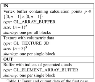
All calculations were performed on an AMD Phenom II X6 1090T 3.2GHz computer with an nVidia GeForce GTX 460 graphics card. Figure 3 presents datasets used in tests; Armadillo and Asian Dragon from The Stan-ford 3D Scanning Repository, Engine and Skull from http://www.volvis.org/. In addition, three-dimensional animated Perlin noise has been used as a dynamic, time-dependent data. All tests were run for differentnon one block of data.
(a) Armadillo (b) Asian Dragon
(c) Engine (d) Skull
Figure 3: Datasets used for tests
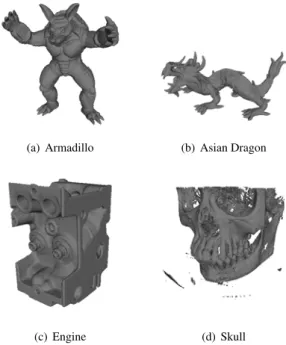
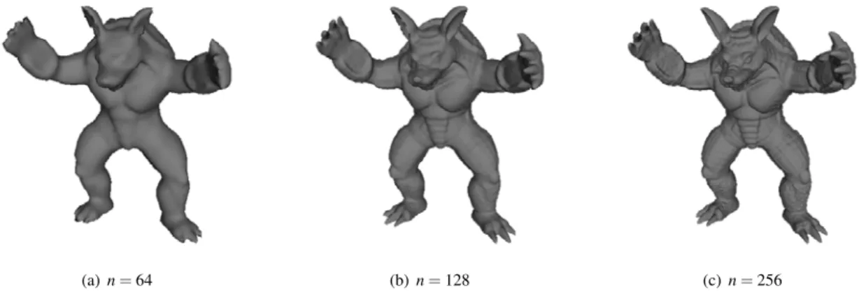
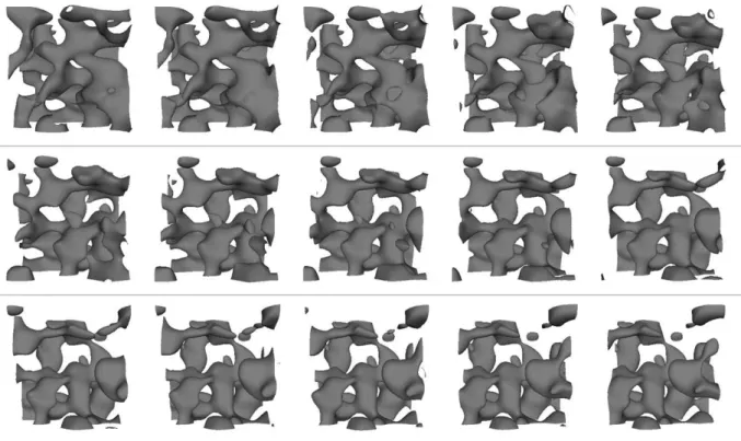
Table 3 lists times for mesh generation and rendering for different block sizes and different data sets. All meshes were regenerated from volumetric data each frame; moreover, calculations for time-dependent Per-lin noise data were also performed before mesh gener-ation every frame. Generated meshes for the Armadillo dataset for different block sizes are presented on figure 4, results for noise dataset are presented on figure 6.
dataset n triangle count fps
Armadillo 64 14180 1100
Armadillo 128 91958 208
Armadillo 256 494880 28
Asian Dragon 64 5864 1180
Asian Dragon 128 41578 234
Asian Dragon 256 229840 30
Engine 256 592884 29
Skull 256 1699526 23.6
Perlin Noise 128 180k-246k 60
Table 3: Results for different block sizes and data sets Table 4 presents results for our method compared to [Goe05, JC06]. The Engine and Skull datasets were used, no preprocessing were performed for these data. As it can be seen our algorithm performs much faster, however, if all methods would be run on the same hard-ware configuration, the difference could be less signifi-cant. Both methods of [Goe05] and [JC06] were tested on nVidia GeForce 6800GT graphics card.
The Marching Cubes algorithm described in [Gei07] seems to execute faster than [Goe05, JC06] methods but no measurable results were published. Authors of [Gei07] claims that their algorithm executes in
interac-(a)n=64 (b)n=128 (c)n=256
Figure 4: Generated mesh for the Armadillo dataset tive frames but mesh generation are not performed each
frame.
dataset size method fps
engine 256x256x110 [Goe05] 3.6
engine 256x256x128 [JC06] 2.8
engine 256x256x256 our method 29
skull 256x256x225 [Goe05] 2.4
skull 256x256x256 [JC06] 1.5
skull 256x256x256 our method 23.6 Table 4: Results compared to previous GPU-based methods
7
MESH IMPROVEMENTS
The presented method works well for smooth surfaces, such as the ones presented in figure 6. In case of sur-faces with sharp edges we see artifacts as it is shown in figure 5(a).
(a) Artifacts on sharp edges
(b) Smoothed mesh
Figure 5: Mesh improvements due to smoothing In order to improve visual quality of the generated sur-face, in the second pass of the algorithm a smoothing
process based on normals is performed about 10 times. Next, during transforming quadrangles into strips of tri-angles, the quadrangles are divided along the shorter diagonal. The last step of smoothing the mesh is com-putation of normals for every pixel in fragment shader, on the basis of volumetric data. Normals are calculated in the same way as for the mesh vertices. The smoothed mesh is presented in Figure 5(b).
8
CONCLUSION AND FUTURE
WORK
In this paper we present a real-time algorithm for gener-ating a three-dimensional mesh fully based on volumet-ric data. This method has been optimized for graphics processors and provides a significant advantage over the already existing solutions for conventional processors. The presented algorithm is also very well suited for the visualization of dynamic data, because the calculations carried out do not need to know the state of the algo-rithm from previous time steps.
With the resulting performance, practical application of the algorithm in digital sculpting software, earth-moving machineries simulators and computer games is fully possible. The tests show a significant advantage of GPUs. The volumetric data representation that has been used allows also for efficient data modification us-ing GPUs.
As part of further work on the algorithm it would be rea-sonable to add support for levels of detail (LOD), so as to enable the process to connect continuously adjacent blocks containing cubes of different sizes and densities. The second issue is to optimize the algorithm by an additional parallelization and simultaneous calculation carried out for 4 blocks. It would be possible in the case of using all four available texture channels. As a result, it would be possible to generate meshes for the four blocks at the same time.
9
ACKNOWLEDGEMENTS
The work described in this paper was partially sup-ported by The European Union by means of European
Social Fund, PO KL Priority IV: Higher Education and Research, Activity 4.1: Improvement and Development of Didactic Potential of the University and Increasing Number of Students of the Faculties Crucial for the National Economy Based on Knowledge, Subactivity 4.1.1: Improvement of the Didactic Potential of the AGH University of Science and Technology “Human Assets”, No. UDA-POKL.04.01.01-00-367/08-00. One of us (WA) kindly acknowledges partial support by Ministry of Science and Higher Education in Poland, project No. N N519 443039.
10
REFERENCES
[Blo88] J. Bloomenthal. Polygonization of im-plicit surfaces.Comput. Aided Geom. Des., 5(4):341–355, 1988.
[CNLE09] Cyril Crassin, Fabrice Neyret, Sylvain Lefebvre, and Elmar Eisemann. Gigavox-els: ray-guided streaming for efficient and detailed voxel rendering. InI3D ’09: Pro-ceedings of the 2009 symposium on In-teractive 3D graphics and games, pages 15–22, New York, NY, USA, 2009. ACM. [GDL+02] Benjamin Gregorski, Mark Duchaineau,
Peter Lindstrom, Valerio Pascucci, and Kenneth I. Joy. Interactive view-dependent rendering of large isosurfaces. InVIS ’02: Proceedings of the conference on Visual-ization ’02, pages 475–484, Washington, DC, USA, 2002. IEEE Computer Society. [Gei07] Ryan Geiss. Generating Complex Proce-dural Terrains using the GPU, chapter 1. GPU Gems. Addison Wesley, 2007. [Gib98] Sarah F. Frisken Gibson. Constrained
elastic surface nets: Generating smooth surfaces from binary segmented data. In MICCAI ’98: Proceedings of the First International Conference on Medical Im-age Computing and Computer-Assisted In-tervention, pages 888–898, London, UK, 1998. Springer-Verlag.
[Goe05] F. et al. Goetz. Real-time marching cubes on the vertex shader. InIn Proceedings of Eurographics 2005, Dublin, Ireland , pp. 5-8, 2005.
[HSIW96] A. Hilton, A. J. Stoddart, J. Illingworth, and T. Windeatt. Marching triangles: range image fusion for complex object modelling. InProc. Conf. Int Image Pro-cessing, volume 1, pages 381–384, 1996. [JC06] Gunnar Johansson and Hamish Carr.
Ac-celerating marching cubes with graphics hardware. InIn CASCON ’06: Proceed-ings of the 2006 conference of the Center
for Advanced Studies on Collaborative re-search, ACM, page 378. Press, 2006. [JLSW02] Tao Ju, Frank Losasso, Scott Schaefer, and
Joe Warren. Dual contouring of hermite data. InSIGGRAPH ’02: Proceedings of the 29th annual conference on Computer graphics and interactive techniques, pages 339–346, New York, NY, USA, 2002. ACM.
[KKDH07] Michael Kazhdan, Allison Klein, Ke-tan Dalal, and Hugues Hoppe. Uncon-strained isosurface extraction on arbitrary octrees. InSGP ’07: Proceedings of the fifth Eurographics symposium on Geom-etry processing, pages 125–133, Aire-la-Ville, Switzerland, Switzerland, 2007. Eu-rographics Association.
[KOKK06] Takashi Kanai, Yutaka Ohtake, Hiroaki Kawata, and Kiwamu Kase. Gpu-based rendering of sparse low-degree implicit surfaces. InProceedings of the 4th inter-national conference on Computer graph-ics and interactive techniques in Australa-sia and Southeast AAustrala-sia, GRAPHITE ’06, pages 165–171, New York, NY, USA, 2006. ACM.
[KOR08] John Kloetzli, Marc Olano, and Penny Rheingans. Interactive volume isosurface rendering using bt volumes. InI3D ’08: Proceedings of the 2008 symposium on In-teractive 3D graphics and games, pages 45–52, New York, NY, USA, 2008. ACM. [KW05] P. Kipfer and R. Westermann. Gpu
con-struction and transparent rendering of iso-surfaces. InVision, Modeling, and Visual-ization (VMV 2005), Erlangen, Germany, Nov. 16-18, 2005.
[LC87] William E. Lorensen and Harvey E. Cline. Marching cubes: A high resolution 3d sur-face construction algorithm. SIGGRAPH Comput. Graph., 21:163–169, August 1987.
[LK10] Samuli Laine and Tero Karras. Efficient sparse voxel octrees. In I3D ’10: Pro-ceedings of the 2010 ACM SIGGRAPH symposium on Interactive 3D Graphics and Games, pages 55–63, New York, NY, USA, 2010. ACM.
[Nie04] Gregory M. Nielson. Dual marching cubes. InProceedings of the conference on Visualization ’04, VIS ’04, pages 489– 496, Washington, DC, USA, 2004. IEEE Computer Society.
Figure 6: Generated meshes for Perlin noise dataset for 15 frames Marc Alexa. Sparse low-degree implicit
surfaces with applications to high quality rendering, feature extraction, and smooth-ing. In Proceedings of the third Euro-graphics symposium on Geometry process-ing, SGP ’05, Aire-la-Ville, Switzerland, Switzerland, 2005. Eurographics Associa-tion.
[OR97] M. Ohlberger and M. Rumpf. Hierarchical and adaptive visualization on nested grids. Computing, 59(4):365–385, 1997. [TPG99] G. M. Treece, R. W. Prager, and A. H.
Gee. Regularised marching tetrahedra: improved isosurface extraction. Comput-ers and Graphics, 23:583–598, 1999. [TSD07] Natalya Tatarchuk, Jeremy Shopf, and
Christopher DeCoro. Real-time isosurface extraction using the gpu programmable geometry pipeline. InACM SIGGRAPH 2007 courses, SIGGRAPH ’07, pages 122–137, New York, NY, USA, 2007. ACM.
[WKE99] R. Westermann, L. Kobbelt, and T. Ertl. Real-time exploration of regular volume data by adaptive reconstruction of iso-surfaces. The Visual Computer, 15:100– 111, 1999.