NC200
Cloud Camera, 300Mbps Wi-Fi
COPYRIGHT & TRADEMARKS
Specifications are subject to change without notice. is a registered trademark of TP-LINK TECHNOLOGIES CO., LTD. Other brands and product names are trademarks or registered trademarks of their respective holders.
No part of the specifications may be reproduced in any form or by any means or used to make any derivative such as translation, transformation, or adaptation without permission from TP-LINK TECHNOLOGIES CO., LTD. Copyright © 2014 TP-LINK TECHNOLOGIES CO., LTD. All rights reserved.
FCC STATEMENT
This equipment has been tested and found to comply with the limits for a Class B digital device, pursuant to part 15 of the FCC Rules. These limits are designed to pro-vide reasonable protection against harmful interference in a residential installation. This equipment generates, uses and can radiate radio frequency energy and, if not in-stalled and used in accordance with the instructions, may cause harmful interference to radio communications. However, there is no guarantee that interference will not occur in a particular installation. If this equipment does cause harmful interference to radio or television reception, which can be determined by turning the equipment off and on, the user is encouraged to try to correct the interference by one or more of the following measures:
• Reorient or relocate the receiving antenna.
• Increase the separation between the equipment and receiver.
• Connect the equipment into an outlet on a circuit different from that to which the receiver is connected.
• Consult the dealer or an experienced radio/ TV technician for help.
This device complies with part 15 of the FCC Rules. Operation is subject to the following two conditions:
1) This device may not cause harmful interference.
2) This device must accept any interference received, including interference that may cause undesired operation.
Any changes or modifications not expressly approved by the party responsible for compliance could void the user’s authority to operate the equipment.
Note: The manufacturer is not responsible for any radio or TV interference caused by unauthorized
modifications to this equipment. Such modifications could void the user’s authority to operate the equipment.
FCC RF Radiation Exposure Statement:
This equipment complies with FCC RF radiation exposure limits set forth for an uncontrolled environment. This device and its antenna must not be co-located or operating in conjunction with any other antenna or transmitter.
“To comply with FCC RF exposure compliance requirements, this grant is applicable to only Mobile Configurations. The antennas used for this transmitter must be installed to provide a separation distance of at least 20 cm from all persons and must not be co-located or operating in conjunction with any other antenna or transmitter.”
CE Mark Warning
This is a class B product. In a domestic environment, this product may cause radio interference, in which case the user may be required to take adequate measures.
Canadian Compliance Statement
This device complies with Industry Canada license-exempt RSS standard(s). Operation is subject to the following two conditions:
(1) This device may not cause interference, and
(2)This device must accept any interference, including interference that may cause undesired operation of the device.
Cet appareil est conforme aux norms CNR exemptes de licence d’Industrie Canada. Le fonctionnement est soumis aux deux conditions suivantes:
(1) cet appareil ne doit pas provoquer d’interférences et
(2) cet appareil doit accepter toute interférence, y compris celles susceptibles de provoquer un fonctionnement non souhaité de l’appareil.
This device has been designed to operate with the antennas listed below, and having a maximum gain of 3 dBi. Antennas not included in this list or having a gain greater than 3 dBi are strictly prohibited for use with this device. The required antenna impedance is 50 ohms.
To reduce potential radio interference to other users, the antenna type and its gain should be so chosen that the equivalent isotropically radiated power (e.i.r.p.) is not more than that permitted for successful communication.
Industry Canada Statement
Complies with the Canadian ICES-003 Class B specifications.
Cet appareil numérique de la classe B est conforme à la norme NMB-003 du Canada.
This device complies with RSS 210 of Industry Canada. This Class B device meets all the requirements of the Canadian interference-causing equipment regulations.
Cet appareil numérique de la Classe B respecte toutes les exigences du Règlement sur le matériel brouilleur du Canada.
Korea Warning Statements:
당해 무선설비는 운용중 전파혼신 가능성이 있음.
NCC Notice & BSMI Notice
注意!
依據 低功率電波輻射性電機管理辦法
第十二條 經型式認證合格之低功率射頻電機,非經許可,公司、商號或使用者均不得擅自變更頻率、
加大功率或變更原設計之特性或功能。
第十四條 低功率射頻電機之使用不得影響飛航安全及干擾合法通行;經發現有干擾現象時,應立即
停用,並改善至無干擾時方得繼續使用。前項合法通信,指依電信規定作業之無線電信。低功率射 頻電機需忍受合法通信或工業、科學以及醫療用電波輻射性電機設備之干擾。
減少電磁波影響,請妥適使用。 安全諮詢及注意事項
●清潔本產品之前請先拔掉電源線。請勿使用液體、噴霧清潔劑或濕布進行清潔。
●注意防潮,請勿將水或其他液體潑灑到本產品上。
●插槽與開口供通風使用,以確保本產品的操作可靠並防止過熱,請勿堵塞或覆蓋開口。
●請勿將本產品置放於靠近熱源的地方。除非有正常的通風,否則不可放在密閉位置中。
●請不要私自打開機殼,不要嘗試自行維修本產品,請由授權的專業人士進行此項工作。
Продукт сертифіковано згідно с правилами системи УкрСЕПРО на відповідність вимогам нормативних документів та вимогам, що передбачені чинними законодавчими актами України.
Safety Information
When product has power button, the power button is one of the way to shut off the product; when there is no power button, the only way to completely shut off power is to disconnect the product or the power adapter from the power source.
Don’t disassemble the product, or make repairs yourself. You run the risk of electric shock and voiding the limited warranty. If you need service, please contact us.
Avoid water and wet locations.
This product can be used in the following countries:
AT BG BY CA CZ DE DK EE
ES FI FR GB GR HU IE IT
LT LV MT NL NO PL PT RO
DECLARATION OF CONFORMITY
For the following equipment:
Product Description: Cloud Camera, 300Mbps Wi-Fi
Model No.: NC200 Trademark: TP-LINK
We declare under our own responsibility that the above products satisfy all the technical regulations applicable to the product within the scope of Council Directives:
Directives 1999/5/EC, Directives 2004/108/EC, Directives 2006/95/EC, Directives 1999/519/EC, Directives 2011/65/EU
The above product is in conformity with the following standards or other normative documents
EN 300 328 V1.8.1
EN 301 489-1 V1.9.2 & EN 301 489-17 V2.2.1 EN 55022: 2010 + AC: 2011
EN 55024: 2010
EN 61000-3-2: 2006 + A1: 2009 + A2: 2009 EN 61000-3-3: 2013
EN 60950-1: 2006 + A11: 2009 + A1: 2010 + A12: 2011 EN 62311: 2008
The product carries the CE Mark:
Person responsible for making this declaration:
Yang Hongliang
Product Manager of International Business
Date of issue: 2014
CONTENTS
Chapter 1
About this Guide ... 2
1.1 Conventions ... 2
1.2 Overview of This Guide ... 2
Chapter 2
Introduction ... 3
2.1 Overview ... 3
2.2 Main Features ... 3
2.3 Appearance Description ... 4
2.3.1 Front Panel ... 4
2.3.2 Rear Panel ... 5
2.4 Mount the Camera ... 6
2.4.1 The Screw Size ... 6
2.4.2 Mount the Camera... 6
Chapter 3
Managing the Camera... 8
3.1 Login ... 8
3.2 Live View ... 9
3.3 Basic ... 11
3.3.1 Basic → Status ... 11
3.3.2 Basic → Network ... 13
3.3.3 Basic → Wireless Connection ... 14
3.3.4 Basic → Cloud Settings ... 16
3.3.5 Basic → LED ... 17
3.4 Advanced ... 17
3.4.1 Advanced → Status ... 18
3.4.2 Advanced → Network ... 18
3.4.3 Advanced → Wireless Connection ... 22
3.4.4 Advanced → Wireless Extender ... 24
3.4.5 Advanced → Cloud Settings... 25
3.4.6 Advanced → DDNS ... 25
3.4.7 Advanced → Video ... 26
3.4.8 Advanced → Motion Detection ... 27
3.4.9 Advanced → Notification Sending ... 28
3.4.10 Advanced → LED ... 33
3.5 System ... 33
3.5.1 Account ... 33
3.5.2 Date/Time ... 36
3.5.3 Management ... 37
3.5.4 System Log ... 39
Appendix A: Specifications ... 41
Chapter 1 About this Guide
This User Guide contains information for setup and management of NC200 Cloud Camera, 300Mbps Wi-Fi. Please read this guide carefully before operation.
1.1 Conventions
In this Guide the following conventions are used:
The camera or NC200 mentioned in this Guide stands for NC200 Cloud Camera, 300Mbps
Wi-Fi without any explanation.
Bold font indicates a button, a toolbar icon, menu or menu item.
Symbol in this Guide:
Symbol Description
Note: Ignoring this type of note might result in a malfunction or damage to the device.1.2 Overview of This Guide
Chapter Introduction
Chapter 1 About This Guide Introduces the guide structure and conventions
Chapter 2 Introduction Introduces the features, application and appearance of NC200 Cloud Camera, 300Mbps Wi-Fi
Chapter 3 Managing the Camera
Introduces how to quickly set up the camera using the built-in web management page
Appendix A Specifications Introduces the specifications of NC200 Cloud Camera, 300Mbps Wi-Fi
Chapter 2 Introduction
Thanks for choosing the NC200 Cloud Camera, 300Mbps Wi-Fi!
2.1 Overview
NC200 is a versatile solution for home & office monitoring to keep an eye on your home, kids or workplace; whatever it is that you care for most.
NC200 has a complete system with a built-in CPU and web server that transmits high quality video images, which can fully meet the need of your small office or home’s security and surveillance. NC200 is an affordable and fully scalable surveillance camera. Because the camera can be added to your existing local area network (LAN) with a stable high speed Wi-Fi connection, you will potentially save a lot from unnecessary cabling. With wireless extender feature, it can also be used as a Wi-Fi range extender to easily expand your Wi-Fi network.
NC200 can be accessed remotely, and controlled from any computer over your local network or through the Internet via a web browser. NC200 is a complete and cost-effective home or office security solution for it comes with remote monitoring and motion detection feature.
NC200 is a cloud-based Wi-Fi video monitoring device with free live streaming and remote viewing, which makes it easy to stay connected with what you care most wherever you are. You can view and manage your camera from anywhere over the Internet through the TP-LINK Cloud website or through the tpCamera app for iOS and Android.
2.2 Main Features
• Monitor your home or office remotely with web-based management page
• iOS and Android app for remote viewing and management with TP-LINK Cloud
• TP-LINK Cloud (www.tplinkcloud.com) access for easy viewing and management
• Email or FTP notification triggered by motion detection
• Supports wireless 802.11b/g/n with speed up to 300Mbps
• Wireless connectivity compliant with WPS button
• Instantly eliminates the dead zones and expand your home’s wireless network
• Ethernet port for wired connectivity
• UPnP support for network setup & configuration
2.3 Appearance Description
2.3.1 Front Panel
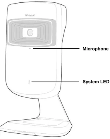
Figure 2-1 Front Panel
Microphone: The camera has a built-in internal microphone. This microphone is hidden in the pinhole located on the front panel.
System LED:
Status Indication
Flashing Red The camera starts booting up.
Solid Red The camera has boot up, but is not connected to any network.
Flashing Green The camera is in firmware upgrade procedure.
Solid Green The camera is connected to a network or is transferring data.
System LED Microphone
2.3.2 Rear Panel
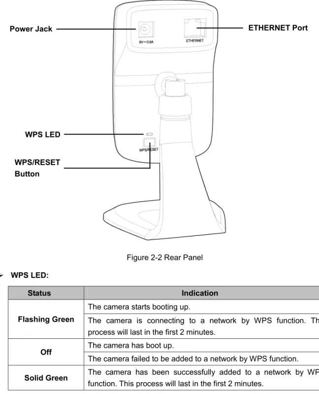
Figure 2-2 Rear Panel
WPS LED:
Status Indication
Flashing Green
The camera starts booting up.
The camera is connecting to a network by WPS function. This process will last in the first 2 minutes.
Off The camera has boot up.
The camera failed to be added to a network by WPS function.
Solid Green The camera has been successfully added to a network by WPS function. This process will last in the first 2 minutes. ETHERNET Port: The ETHERNET port is used to connect the camera to a network via RJ45
cable.
Power Jack: The power jack is where you connect the AC adapter to the camera.
WPS/RESET Button: This button is used for both WPS and RESET function. To use the WPS function, press it for 1 second; to use the RESET function, press and hold for more than 5 seconds.
ETHERNET Port
WPS/RESET Button
WPS LED Power Jack
Used as RESET button:
With the camera powered on, press and hold the WPS/RESET button (more than 5 seconds) until both the System LED and WPS LED turn off. Then release the button and wait the camera to reset to its factory default settings.
Used as WPS button:
If your router supports WPS, then you can press the WPS/RESET button for 1 second to quickly establish a connection between the camera and router.
2.4 Mount the Camera
2.4.1 The Screw Size
2.4.2 Mount the Camera
Note:If you use the camera wirelessly, mount the camera within the coverage of your wireless network.
3. Drill two mounting holes and fix the mounting base.
Chapter 3 Managing the Camera
The camera’s built-in web management page is designed to allow you to easily access and configure your camera.
Use the management IP address of the camera to log in to the camera. You can find the IP address in two ways:
Run the Setup Wizard. The IP address is displayed on the Select a camera screen.
Find the IP address on the DHCP setting page of the front device such as router.
3.1 Login
1. Open a Web browser and type in the IP address of the camera you want to monitor in the address field of the browser.
2. Enter the default username and password (admin/admin). Click Login to start the main menu.
Note:For the administrator, the default password is “admin”. We recommend you to change it in the Account menu. (Go to “System → Account”)
If you log in to the camera as an administrator, you can perform all the settings provided by the camera.
If you log in to the camera as a user, you can only view the Live View. After logging as administrator, you can add up to five user accounts in the Account menu. (Go to “System → Account”)
Note:If the installed plugin doesn't work, set your browser security settings to allow plugins. Here we take the settings for IE browser as an example. Go to "Tools→Internet Options→Security". Click "Internet→Custom Level", find the item "Download signed ActiveX controls" and check Prompt. Click "Local Intranet→Custom Level", find the item "Download signed ActiveX controls" and check Prompt.
4. After the plugin is successfully installed, refresh the webpage to display the monitor video.
3.2 Live View
The Live View screen shows you the live video feed from your camera. On this screen, you can capture a picture, record a video, change the resolution and so on.
Symbols Meaning Note
Click to capture a still image shot by the camera.
The image file will be saved in JPG or BMP format in your local computer. The file is named as image-yyyy-mm-dd-hh-mm-ss.jpg. You can select a save path and rename the image file.
Click to record the current video.
The video file will be saved in AVI format in your local computer. The file is named as rec-yyyy-mm-dd-hh-mm-ssi.avi. You can select a save path and rename the video file.
The icon will turn yellow once the save path is selected. If you want to stop recording, just click .
Click to vertically flip the current image.
If the camera is installed upside down, Flip Image and Mirror should both be checked.
Click to horizontally flip the current image.
Drag the slider to adjust the size of the current image.
The maximum zoom ratio is 4 times. Mute off. You can hear the
current sound by the camera.
Click and it will become .
Mute on. The current sound by the camera is turned off.
Click and it will become .
Drag the slider to adjust the sound volume.
You can adjust the sound volume only with mute off .
Click to enlarge the current image to full screen display.
Press “ESC” key to return to the original screen display.
Brightness: Drag the slider to adjust the brightness level of camera. Large value will brighten the current displayed screen.
Contrast: Drag the slider to adjust the contrast level of the camera. Large value will contrast the current displayed screen heavily.
Saturation: Drag the slider to adjust the saturation level of the camera. Large value will saturate the current displayed screen to be more colorful.
Resolution: Select the desired video resolution between two formats: 640*480 and 320*240. Higher setting offers better quality, but will require more bandwidth to stream.
Preset: Click the Preset button to restore to factory image settings.
3.3 Basic
Click the Basic menu to display the submenus including Status, Network, Wireless Connection,
Cloud Settings, and LED.
3.3.1 Basic → Status
3.3.2 Basic → Network
On this page, you can configure your camera’s IP address which is used to access and configure the camera.
Dynamic IP: Select this option when a DHCP server is installed on the network to issue IP address assignment. With this setting, the IP address of the camera is assigned automatically.
Static IP: Select this option when a static or fixed IP address is obtained for the camera. A static IP address will ease your access to the camera in the future. Add your camera’s static IP information to your router to avoid IP conflicts.
MAC Address: Displays the Ethernet MAC address of the camera. The MAC address is read-only.
IP Address: Enter a fixed IP address for the camera in dotted-decimal notation.
Subnet Mask: Enter the subnet mask in dotted-decimal notation. The default value is “255.255.255.0.”
Default Gateway: Enter the default gateway in dotted-decimal notation.
Primary DNS Server: Enter a DNS address in dotted-decimal notation.
Click Save to save and enable the settings.
3.3.3 Basic → Wireless Connection
The camera’s wireless function is enabled by default. This function helps to connect your camera to a wireless network wirelessly. If you don’t want to use this function, just select the Disable option.
Wireless Network Name: Displays the wireless network’s name. Make sure the camera and your PC connect to the same wireless network, or your PC can't access the camera.
Signal: Displays the strength of the wireless signal.
Security: Displays the wireless network’s security mode.
MAC Address: Displays the MAC address of the front device.
To connect your camera to a wireless network, follow the steps below:
1. Click Scan to scan the available wireless network and to refresh the Wireless Network List. 2. Select a wireless network from the wireless network list.
3. If the wireless network’s security mode is None, simply click Connect. If the security mode is one requiring for a password, enter the wireless network’s password and then click Connect.
You can select Show password to display what you’ve entered.
4. A pop-up screen will prompt you for the network modification. Click Change to continue.
6. To start using camera wirelessly, unplug its Ethernet cable.
3.3.4 Basic → Cloud Settings
NC200 is a Cloud Camera which can be viewed anytime and anywhere over the Internet with TP-LINK Cloud service. On this page, you can add your camera to an existing TP-LINK Cloud account or you can sign up for a TP-LINK Cloud account and then add your camera to it.
Note:To add a camera to TP-LINK Cloud account or to sign up for a TP-LINK Cloud account, make sure that the camera is connected to the Internet.
Add Your Camera to TP-LINK Cloud Account
If you already have a TP-LINK Cloud account, to add your camera to your account, just enter the TP-LINK Cloud account and password, and then click Register.
Account: Enter your TP-LINK Cloud account, either E-mail address or username is allowed.
Password: Enter your TP-LINK Cloud account’s password.
an easy-remember one. Camera name can contain up to 30 characters. It can only contain digits, letters, space and .-_@'.
After your camera is registered successfully, you can go to www.tplinkcloud.com to view it.
Sign Up for a TP-LINK Cloud Account
If you do not have a TP-LINK Cloud account, click Don’t have an account? to sign up.
E-mail: Enter a valid E-mail address as your TP-LINK Cloud account. If you forget your TP-LINK Cloud password, you can reset it via this E-mail address.
Username: Enter a username as your TP-LINK Cloud account. Username should contain 1-32 characters. It can only contain letters, digits and . - _.
Password: Enter a password for your TP-LINK Cloud account. Password should contain 6-20 characters. It can only contain letters, digits and .- _ ! @ # $,% ^& *.
Confirm Password: Enter the password again to confirm it.
Click Sign up to sign up for a TP-LINK Cloud account. After signing up successfully, you can add your camera to this account. Click Back if you don’t want to sign up.
3.3.5 Basic → LED
The camera’s LED is on by default. If you want to turn it off, just select Off.
3.4 Advanced
Connection, Wireless Extender, Cloud Setting, DDNS, Video, Motion Detection, Notification Sending, and LED.
3.4.1 Advanced → Status
Refer to 3.3.1 Basic → Status.
3.4.2 Advanced → Network
IP Address
On this page, you can configure your camera’s IP address which is used to access and configure the camera.
Dynamic IP: Select this option when a DHCP server is installed on the network to issue IP address assignment. With this setting, the IP address of the camera is assigned automatically.
Fallback IP: If the camera cannot get a Dynamic IP address from a DHCP server within limited tries, the camera will assign a default IP address, 192.168.0.10, by itself as the Fallback IP address.
Static IP: Select this option when a static or fixed IP address is obtained for the camera. A static IP address will ease your access to the camera in the future. Add your camera’s static IP information to your router to avoid IP conflicts.
MAC Address: Displays the Ethernet MAC address of the camera. The MAC address is read-only.
IP Address: Enter a fixed IP address for the camera in dotted-decimal notation.
Subnet Mask: Enter the subnet mask in dotted-decimal notation. The default value is “255.255.255.0.”
Default Gateway: Enter the default gateway in dotted-decimal notation.
Primary DNS Server: Enter a DNS address in dotted-decimal notation.
Secondary DNS Server: Enter a DNS address in dotted-decimal notation.
PPPoE (Point to Point Protocol over Ethernet)
This camera is a PPPoE enabled one. It can directly connect to the xDSL, however, it should be set up in a LAN environment to configure the PPPoE information first, and then connect to the xDSL modem. Power on again, and the camera will dial on to the ISP to get a dynamic IP address and connect to the WAN through the xDSL modem. In this case, you need to use a domain name to log in to the camera. For details, please refer to 3.4.6 Advanced → DDNS.
PPPoE: To enable or disable the PPPoE service here.
Status: Displays the PPPoE connection status.
Username: Enter the username for PPPoE service provided by your ISP.
Password: Enter the password for PPPoE service provided by your ISP.
HTTP (Hypertext Transfer Protocol)
This feature allows you to access and manage your camera from a remote location over the Internet. Web browser access normally uses the standard HTTP service port 80. This camera's default remote management web port number is 80. For greater security, you can change the port to a custom one.
When you have set the HTTP port number to a number other than 80, a corresponding port must be opened on the router.
Access the camera by typing the IP address of the camera on the Web browser as follows: for example, when HTTP port number is set to 2000 and the IP address of your camera is set to 192.168.1.100, you should type in http://192.168.1.100:2000 instead of http://192.168.1.100 to access the camera.
HTTP Port: The default value is 80. If you want to use a port number other than 80, enter a port number between 1 and 65535.
UPnP (Universal Plug and Play)
This camera is an UPnP enabled one. This means the camera can dynamically join a network, obtain an IP address. In turn, the camera can leave a network smoothly and automatically when it is no longer in use. UPnP is enabled by default; if you don’t want to use this function, just select the Disable option.
UPnP Port Forwarding: To enable or disable the UPnP Port Forwarding service here. If this function is enabled and your router supports UPnP, the cameras and router can communicate with each other so that the router knows which ports are used by which camera.
Bonjour
Bonjour, also known as zero-configuration networking, enables automatic discovery of computers, devices, and services on IP networks. Bonjour uses industry standard IP protocols to allow devices to automatically discover each other without the need to enter IP addresses or configure DNS servers.
Bonjour: To enable or disable the Bonjour service here.
Bonjour Name: Displays the Bonjour name. By default, it is a combination of model and the last six characters of the camera’s MAC address.
Click Save to save and enable the settings.
3.4.3 Advanced → Wireless Connection
The camera’s wireless function is enabled by default. With this function enabled, you can connect your camera to a wireless network wirelessly. If you don’t want to use this function, just select the Disable option.
On this page, you can either scan a wireless network to connect to or enter a wireless network’s parameters manually. To scan a wireless network, refer to 3.3.3 Basic → Wireless Connection. To enter the parameters manually, see the following.
1. Select Enable to enable your camera’s wireless function. 2. Click Manually, and you will see the following screen.
3. In the Wireless Network Name field, enter the name of the wireless network to which your camera is ready to connect.
Note:The name must be exactly the same as that used in the wireless access point, or the connection will not be established. Leaving this field blank means the camera will attempt to access the nearest open network. If your PC wants to access the camera, make sure your PC and the camera are connecting to the same wireless network.
4. Select the wireless security mode used by your wireless network from the drop-down list. The security mode and its corresponding settings must be exactly the same as that used in the
wireless network.
5. Click Connect and a screen will pop up. Click Change on the pop-up screen. 6. Click OK on the pop–up screen to finish wireless connection procedure. 7. To start using camera wirelessly, unplug its Ethernet cable.
3.4.4
Advanced → Wireless Extender
On this page, you can setup and configure the wireless network extending feature of your camera. Wireless extender function allows your camera to extend the range of your existing wireless network. The same network name and settings as the existing wireless network can be used, or you can create a new one.
The camera’s wireless extender function is disabled by default. If you want to use this function, just select the Enable option.
Host Wireless Network Name: Displays the name of the wireless network which your camera is connected to. It is read-only.
Extended Wireless Network Name: Name of the wireless network that your camera will extend.
Same as Host: The extended network will use the same name and settings as your Host network. Your devices can use the same wireless information to connect to both the host and extended networks.
Create a New One: Select this to manually set the name and security used for the extended network. You devices can use the wireless parameters you set to connect to the extended network.
Max Clients: Set the maximum number of clients that are allowed to connect to the extended network.
Click Save to save and enable the settings.
3.4.5 Advanced → Cloud Settings
Refer to 3.3.4 Basic → Cloud Settings.
3.4.6
Advanced → DDNS
If your camera is connected to xDSL modem or cable modem directly, you might need this feature on the camera to allow you and your friends have access to the camera using domain name, in no need of remembering the IP address. However, if your camera is behind a NAT router, you need to set DDNS on your router, in no need of setting this on the camera. As to xDSL environment, most users will use dynamic IP addresses. If users want to set up a web or a FTP server, then the DDNS (Dynamic Domain Name Server) is necessary.
(www.noip.com), DynDNS (www.dyn.com), and Comexe (www.comexe.cn).
Note:If you have not registered for any of the listed DDNS servers, please select one and click Go to register…and follow the instructions provided on the official website to register.
Username: Enter the username that is used to log into DDNS.
Password: Enter the password that is used to log into DDNS.
Domain Name: Enter the domain name that is applied to your camera and used to access your camera.
Connection Status: Displays the current status of DDNS connection.
Click Login. After logging in successfully, click Save to save and enable the settings.
3.4.7
Advanced → Video
On this page, you can configure the video settings for your camera.
Frame Rate: Select the frame rate to use for the video stream from the drop-down list. Higher settings offer better quality, but will require more bandwidth to stream.
Image Quality: Select one of the three levels of image quality from the drop-down list: High, Medium, and Low. Higher settings offer better quality, but will require more bandwidth to stream.
Backlight Compensation: If enabled, this feature will compensate for bright backgrounds so foreground objects aren't silhouetted. It is enabled by default.
Light Frequency: Select the frequency used by your lighting and power to help reduce image flicker. The default setting is auto, which is recommended.
Time Stamp: If enabled, the current time of your camera, which can be set on System →
Date/Time page, will be displayed on the top right corner of the live view screen. With this feature enabled, you can find out the exact time of the snapshot or record easily.
On-Screen Display (OSD): If enabled, you can set the OSD text and the OSD text you entered will be displayed on the top left corner of the live view screen. The OSD text is camera name by default.
If Backlight Compensation, Time Stamp, and OSD are all enabled, see the following two pictures to see the differences:
Click Save to save and enable the settings.
3.4.8 Advanced → Motion Detection
Motion detection allows you to specify areas of your camera’s video to monitor for motion, which can be used to trigger snapshots. Refer to 3.4.9 Advanced → Notification Sending for more details.
Motion Detection: To enable or disable the motion detection function here.
Sensitivity: Specify the level of difference between two sequential images that would indicate motion. Select one of the three levels of sensitivity from the drop-down list: High, Medium, and Low.
Use your mouse to click on the parts of screen where you would like to monitor for motion. Click
Save to save and enable the settings.
3.4.9
Advanced → Notification Sending
Notification Sending settings are available only after the Motion Detection function is enabled. Notification sending function is used to inform you immediately by sending the snapshots, which are triggered by the camera’s motion detection function, to the specified FTP server or E-mail address.
FTP
Select FTP, you can configure your camera to send snapshots to a specified FTP sever on the following screen:
FTP Server/ Port: Enter the IP or the domain (IP/domain without prefix ftp://) and the port of the FTP server that you will be connecting to. The port is 21 by default.
Note:The FTP server you set and the camera should be in the same LAN.
Username: Enter the username that is used to log in to your FTP server.
Password: Enter the password that is used to log in to your FTP server.
Path: Enter the path to the destination on the FTP server.
Passive Mode: Enabling passive mode may help you reach your FTP server if your camera is behind a router protected by a firewall.
1. Enter an IP address or domain of your FTP server, e.g. 192.168.1.168 2. Remain the FTP port number as the default value: 21.
3. Enter your username to log in to the FTP server, e.g. test. 4. Enter your password to log in to the FTP server.
5. Enter the path to the destination on the FTP server, e.g. /test 6. Enable Passive Mode.
7. Click Save to save and enable the settings.
Click Test, and a test JPEG snapshot will be sent to the specified FTP server to check whether your settings are correct.
If the settings are tested correct, you will see the following screen. Click OK.
If the settings are tested incorrect, you will see the following screen. Click OK. Please check your network and FTP settings and try again later.
Select E-mail, you can configure your camera to send snapshots to a specified E-mail address on the following screen.
Recipient E-mail Address: Enter the receiver’s E-mail address that the notification E-mail will be sent to. Click Add recipient to add receiver’s E-mail addresses. You can specify up to four recipient E-mail addresses.
SMTP Server/Port: Enter the domain name or IP address and the port of your external E-mail server. The port is 25 by default.
Sender E-mail Address: Enter the sender’s E-mal address that is used to send the notification E-mail.
Password: Enter your password if the SMTP server uses authentication.
SSL Encryption: Select TLS or STARTTLS as the SSL encryption; select Close to disable SSL encryption.
Note:If TLS is selected as the SSL Encryption, set the Sender E-mail Port as 465; if STARTTLS is selected, set the Port as 25 or 587.
Sending Interval: Set the limit for how frequently E-mail notifications will be sent. Select one interval from the drop-down list.
For example, if you want to use Gmail with TLS for E-mail notifications, follow the steps below:
1. Enter the receiver’s E-mail address in Recipient E-mail Address, e.g. [email protected]. 2. Enter smtp.gmail.com in SMTP server.
3. Enter your Gmail E-mail address in Sender E-mail Address, e.g. [email protected] 4. Enter the password required to access the SMTP server.
5. Select TLS as the SSL encryption and the SMPT server port number will be changed to 465
automatically.
6. Set the Sending Interval, e.g. 1m.
7. Click Save to save and enable the settings.
Click Test, and a test JPEG snapshot will be sent to the recipient E-mail address to check whether your settings are correct.
If the settings are tested incorrect, you will see the following screen. Click OK. Please check your network and E-mail settings and try again later.
3.4.10 Advanced → LED
Refer to 3.3.5 Basic → LED.
3.5 System
Click the System folder to display the sub folders including Account, Date/Time, Management, and System Log.
3.5.1 Account
are allowed to access to your camera.
Username: Displays the name of user account.
User Group: Displays the group the user account is in. Different user group has different limits of authority.
admin: Admin group has all authority of configuration. It can only have one account: admin.
user: User group can only view the Live View. It can have up to five accounts.
Add a New User Account
You can create new user account to provide viewing access for your camera’s video. User accounts will only be able to access the Live View section of the web configuration page, but cannot access any other parts or change any settings.
To add a new user account, follow the steps below:
1. Click Add, and you will see the following screen.
3. Enter a password for your new account. The password should contain 5~20 characters. 4. Enter the password again to confirm it.
5. Click Save to save and enable the settings.
Change Password
You can change the password of all the accounts here.
Note:The default account and password are both admin. Everyone who knows the camera’s IP address can access the device with all configuration authority. It is necessary to change the default password if the device is intended to be accessed only by administrator.
To change password, follow the steps below:
1. Select one user account in the list whose password you want to change 2. Click Change Password, and you will see the following screen.
3. Enter the current password in the Old Password textbox. 4. Enter a new password.
5. Enter the new password again to confirm it. 6. Click Save to save and enable the settings.
You can delete a user account except admin here. Select one in the list and click Delete.
3.5.2 Date/Time
On this page, you can configure the settings of the internal system clocks for your camera.
Current Time: Displays the current date and time of the camera.
Time Zone: Select the time zone for the region where the camera is installed from the drop-down list. Auto Time zone is recommended.
Enable Daylight Saving Time: Select this option to enable daylight saving time adjustment. If enabled, you will see the following screen:
Automatically: If selected, the internal system clocks of the camera will adjust the DST automatically.
Manually: If selected, you can adjust the DST by setting the Time Offset, Start Time, and End Time.
Synchronize With NTP Server: Select this option to specify the NTP server name to synchronize the date and time of the camera with those of the time server, known as the NTP (Network Time Protocol) server. If enabled, you will see the following screen:
NTP Server: You can either enter a domain name of the NTP server or select one which will be filled in automatically from the drop-down list.
Set NTP Server from Dynamic IP: You can use the NTP server applied in the DHCP server on the network.
Set Date and Time Manually: Select this option to set the date and time of the camera manually. If enabled, you will see the following screen:
Copy Your Computer’s Time Settings: Click this button to copy your computer’s current time settings.
Click Save to save and enable the settings.
3.5.3 Management
On this page, you can reboot the camera, backup and restore the camera’s current settings, reset factory settings, and update the camera’s software.
Reboot: Click Reboot and then click Reboot on the pop-up screen to confirm. Rebooting will not change the camera’s setting. After rebooting, you need to log in to this page again.
Backup: Click Backup and follow the instructions on the browser to save the setting data file to your specified location.
Restore: Click Browse to locate the saved backup file and then click Restore. The camera will start rebooting and then the settings will be restored to the previous configuration.
Reset: Click Reset and then click Reset on the pop-up screen to restore the camera to its factory defaults. Don't turn off the camera while resetting. After resetting, you need to find out the IP address of your camera (refer to 3.1 Login) and use the default username and password (admin/admin) to log in to this page.
Update:
The system will detect whether your camera’s current software is the latest one automatically. If the software is the latest one, you can see a note on the screen: Your software version is the latest one.
If not, a screen will pop up for you to download the latest software and you can follow the steps below to upgrade the software.
2. Click Browse to locate the latest downloaded software.
3. Click Upgrade to update the camera’s software to the latest version.
4. Wait for the uploading process to complete, and the camera will reboot automatically.
Note:1. We recommend you to use a wired connection for your camera and PC when upgrading firmware.
2. The firmware upgrade procedure must not be interrupted or the camera may be damaged. 3. The firmware upgrade procedure is always risky and do not try to upgrade new firmware if it’s
not necessary.
3.5.4 System Log
On this page, you can review any changes and events happened to your camera. The system starts logging automatically after startup.
Time: Displays the time when the log event occurs. The log can get the correct time after you configure on the Date/Time page. (go to Advanced → Date/Time)
Module: Displays the module to which the log information belongs. You can specify the module by selecting one from the Module drop-down list at the bottom.
Level: Displays the severity level of the log information. You can specify the level by selecting one from the Level drop-down list at the bottom.
Content: Displays the details of the log information.
Refresh: Click Refresh to refresh the log information.
Save Log: Click Save Log and follow the instructions on the browser to save the log as a text file named log.txt to your specified location.
Appendix A: Specifications
SYSTEMImage Sensor 1/4’’ Progressive scan CMOS sensor
Resolution 0.3 Megapixel (640*480)
Lens F: 2.8, f: 3.85mm
Viewing Angle FOV=64° Digital Zoom 4x Digital
Video/Image Video Compression MJPEG
Frame Rate & Resolutions Max: 20 fps at 640*480 (VGA)
Max: 30 fps at 320*240 (QVGA)
Video Streaming Controllable frame rate and bandwidth
Image
Rotation: Mirror, Flip, Mirror Flip
Configurable brightness, contrast, saturation Overlay capabilities: time, date, text
Audio Audio Communication 1-way
Audio Input Built-in microphone
Audio Compression PCM
Alarm and Event Management Input Trigger Motion detection
Notification Method E-mail, FTP
Network
Standards and Protocols Bonjour, TCP/IP, DHCP, PPPoE, ARP, ICMP, FTP, SMTP,
TCP, UDP
Security Multiple password-protected user levels
Wireless
Wireless Data Rate IEEE 802.11b/g/n, Up to 300Mbps
Frequency 2.4-2.4835GHz
Wireless Encryption WEP, WPA/WPA2, WPA-PSK/WPA2-PSK
Minimum System Requirements
Supported Browser
Microsoft Internet Explorer 7 or higher Firefox 4.0 or higher
Safari 4.0 or higher Chrome 5.0 or higher Opera 12.0 or higher
Supported OS Windows XP/Vista/7/8
Mac OS X 10.7 or higher
General Certification CE, FCC, RoHS
Environment
Operating Temperature: 0°C ~ 40°C (32℉ ~ 104℉)
Storage Temperature: -20°C ~ 60°C (-4℉ ~ 140℉)
Operating Humidity: 10%-90% non-condensing Storage Humidity: 5%-90% non-condensing
Appendix B: Troubleshooting
Question Answer or Resolution
Features
The maximum number of users accessing the camera simultaneously.
The maximum number of users is limited to 13. However, it also depends on the total bandwidth accessed to this camera from clients. The actual number of connected clients varies by streaming mode, settings of resolution, frame rate and bandwidth. Obviously, the performance of the each connected client will slow down when many users are logged on.
The camera can be used outdoors or not.
The camera is not weatherproof. It needs to be equipped with a weatherproof case for outdoors using. However, equipped with a weatherproof case might disable the audio function of the camera.
Install this camera
System LED does not light up.
Check and confirm that the DC power adaptor, included in
package, is used. Secure the power connector and re-power it on again.
If the problem is not solved, the camera might be faulty.
Contact your dealer for further help. The camera will be
installed and work if a firewall exists on the network.
If a firewall exists on the network, port 80 is open for ordinary data communication. The HTTP port needs to be opened on the firewall or NAT router.
The username and password for the first time or after factory default reset
Username is admin and password is admin. Note that it’s all case sensitive.
Forgot the username and password
Follow the steps below.
1. Restore the factory default setting by pressing and holding the WPS/RESET button (more than 5 seconds) on the camera.
2. Reconfigure the camera. Forgot the IP address of
the camera.
Run the Setup Wizard. The IP address is displayed on the
Select a camera screen.
Find the IP address on the DHCP setting page of the front
device such as router. Internet Explorer does not
seem to work well with the camera
Make sure that your Internet Explorer is version 7.0 or later. If you are experiencing problems, try upgrading to the latest version of Microsoft’s Internet Explorer from the Microsoft webpage.
UPnP NAT Traversal
router check user’s manual of router and turn on UPnP function.
Maybe UPnP function of NAT router is not compatible to the IP
camera. Please contact your dealer to get the approval routers list.
Some cameras are
working but others are failed
Maybe too many cameras have been installed on the LAN, and
then NAT router is out of resource to support more cameras.
You could turn off and on NAT router to clear out of date
information inside router.
Access this camera
Cannot access the web management page and other web pages of the camera from Internet Explorer
Maybe the IP Address of the camera is already being used by
another camera or computer. To confirm this possible problem, disconnect the camera from the network first, and then run the PING utility to check it out.
May be due to the network cable. Try correcting your network
cable and configuration. Test the network interface by connecting a local computer to the camera via a crossover cable.
Make sure the Internet connection and setting is ok.
Make sure the IP address typed in is correct. If the camera has
a dynamic address, it may have changed since you last checked it.
Network congestion may prevent the web page appearing
quickly. Wait for a while.
The IP address and Subnet Mask of the PC and camera must
be in the same class of the private IP address on the LAN.
Make sure the http port used by the camera, default=80, is
forward to the camera’s private IP address.
The port number assigned in your camera might not be
available via Internet. Check your ISP for available port.
The proxy server may prevent you from connecting directly to
the camera, set up not to use the proxy server.
Confirm that Default Gateway address is correct.
The router needs Port Forwarding feature. Refer to your
router's manual for details.
Packet Filtering of the router may prohibit access from an
external network. Refer to your router's manual for details.
Access the camera from the Internet with the global IP address
of the router and port number of camera.
Some routers reject the global IP address to access the
camera on the same LAN. Access with the private IP address and correct port number of camera.
When you use DDNS, you need to set Default Gateway and
DNS server address.
If it’s not working after above procedure, reset camera to
default setting and installed it again.
If the problem is not solved, the camera might be faulty.
Contact your dealer for further help. Image or video does not
appear in the main page.
Make sure the plugin is installed properly and your browser
security settings are set to allow plugins. Close and restart the browser. Try to browse and log in again.
account that is authorized to install applications.
Network congestion may prevent the Image screen from
appearing quickly. You may choose lower resolution to reduce the required bandwidth.
The camera work locally but not externally.
Might be caused from the firewall protection. Check the
Internet firewall with your system or network administrator. The firewall may need to have some settings changed in order for the camera to be accessible outside your LAN.
Make sure that the camera isn’t conflicting with any other web
server running on your LAN.
Check the configuration of the router settings allow the camera
to be accessed outside your local LAN.
Check the bandwidth of Internet connection. If the Internet
bandwidth is lower than target bit rate, the video streaming will not work correctly.
The unreadable characters are displayed.
Use the operating system of the selected language. Set the Encoding or the Character Set of the selected language on the Internet Explorer.
Frame rate is slower than the setting.
The traffic of the network and the object of the image affect the
frame rate. The network congestion causes frame rate slower than the setting.
Check the bandwidth of Internet connection. If the Internet
bandwidth is lower than target bit rate, the video streaming will not work correctly.
Ethernet switching hub can smooth the frame rate.
Image Transfer on e-mail or FTP does not work.
Default Gateway and DNS server address should be set up
correctly.
If FTP does not work properly, ask your ISP or network
administrator about the transferring mode of FTP server.
Video quality of the camera
The focus on the camera is bad.
The lens is dirty or dust is attached. Fingerprints, dust, stain,
etc. on the lens can degrade the image quality.
The color of the image is poor or strange.
To insure the images you are viewing are the best they can be,
set the Display property setting (color quality) to 16bit at least and 24 bit or higher if possible within your computer.
The configuration on the camera image display is incorrect.
You need to adjust the image related parameters such as brightness, contrast, and saturation properly.
Image flickers.
Wrong power line frequency makes images flicker. Make sure
the 50 or 60Hz format of your camera.
If the object is dark, the image will flicker. Make the condition
around the camera brighter.
Miscellaneous
Cannot play the recorded file
Have installed Microsoft®’s DirectX 9.0 or later and use the Windows Media Player 11.0 or later to play the AVI filed recorded by the camera.