Implementation Guide for
Microsoft Exchange 2007
Windows
7.0
The software described in this book is furnished under a license agreement and may be used only in accordance with the terms of the agreement.
Product version: 7.0 Document version: 7.0 Rev 0
Legal Notice
Copyright © 2015 Symantec Corporation. All rights reserved.
Symantec, the Symantec Logo, the Checkmark Logo, Veritas, the Veritas Logo,
CommandCentral, NetBackup, Enterprise Vault, and LiveUpdate are trademarks or registered trademarks of Symantec Corporation or its affiliates in the U.S. and other countries. Other names may be trademarks of their respective owners.
This Symantec product may contain third party software for which Symantec is required to provide attribution to the third party (“Third Party Programs”). Some of the Third Party Programs are available under open source or free software licenses. The License Agreement accompanying the Software does not alter any rights or obligations you may have under those open source or free software licenses. See the Third-party Legal Notices document for this product, which is available online or included in the base release media.
The product described in this document is distributed under licenses restricting its use, copying, distribution, and decompilation/reverse engineering. No part of this document may be reproduced in any form by any means without prior written authorization of Symantec Corporation and its licensors, if any.
THE DOCUMENTATION IS PROVIDED "AS IS" AND ALL EXPRESS OR IMPLIED CONDITIONS, REPRESENTATIONS AND WARRANTIES, INCLUDING ANY IMPLIED WARRANTY OF MERCHANTABILITY, FITNESS FOR A PARTICULAR PURPOSE OR NON-INFRINGEMENT, ARE DISCLAIMED, EXCEPT TO THE EXTENT THAT SUCH DISCLAIMERS ARE HELD TO BE LEGALLY INVALID. SYMANTEC CORPORATION SHALL NOT BE LIABLE FOR INCIDENTAL OR CONSEQUENTIAL DAMAGES IN CONNECTION WITH THE FURNISHING, PERFORMANCE, OR USE OF THIS DOCUMENTATION. THE INFORMATION CONTAINED IN THIS DOCUMENTATION IS SUBJECT TO CHANGE WITHOUT NOTICE.
The Licensed Software and Documentation are deemed to be commercial computer software as defined in FAR 12.212 and subject to restricted rights as defined in FAR Section 52.227-19 "Commercial Computer Software - Restricted Rights" and DFARS 227.7202, "Rights in Commercial Computer Software or Commercial Computer Software Documentation", as applicable, and any successor regulations. Any use, modification, reproduction release, performance, display or disclosure of the Licensed Software and Documentation by the U.S. Government shall be solely in accordance with the terms of this Agreement.
Symantec Technical Support maintains support centers globally. Technical Support’s primary role is to respond to specific queries about product features and functionality. The Technical Support group also creates content for our online Knowledge Base. The Technical Support group works collaboratively with the other functional areas within Symantec to answer your questions in a timely fashion. For example, the Technical Support group works with Product Engineering and Symantec Security Response to provide alerting services and virus definition updates.
Symantec’s support offerings include the following:
■ A range of support options that give you the flexibility to select the right amount of service for any size organization
■ Telephone and/or Web-based support that provides rapid response and up-to-the-minute information
■ Upgrade assurance that delivers software upgrades
■ Global support purchased on a regional business hours or 24 hours a day, 7 days a week basis
■ Premium service offerings that include Account Management Services
For information about Symantec’s support offerings, you can visit our website at the following URL:
www.symantec.com/business/support/index.jsp
All support services will be delivered in accordance with your support agreement and the then-current enterprise technical support policy.
Contacting Technical Support
Customers with a current support agreement may access Technical Support information at the following URL:
www.symantec.com/business/support/contact_techsupp_static.jsp
Before contacting Technical Support, make sure you have satisfied the system requirements that are listed in your product documentation. Also, you should be at the computer on which the problem occurred, in case it is necessary to replicate the problem.
When you contact Technical Support, please have the following information available:
■ Product release level
■ Version and patch level
■ Network topology
■ Router, gateway, and IP address information
■ Problem description:
■ Error messages and log files
■ Troubleshooting that was performed before contacting Symantec ■ Recent software configuration changes and network changes
Licensing and registration
If your Symantec product requires registration or a license key, access our technical support Web page at the following URL:
www.symantec.com/business/support/
Customer service
Customer service information is available at the following URL:
www.symantec.com/business/support/
Customer Service is available to assist with non-technical questions, such as the following types of issues:
■ Questions regarding product licensing or serialization
■ Product registration updates, such as address or name changes
■ General product information (features, language availability, local dealers)
■ Latest information about product updates and upgrades
■ Information about upgrade assurance and support contracts ■ Information about the Symantec Buying Programs
■ Advice about Symantec's technical support options
■ Nontechnical presales questions
contact the support agreement administration team for your region as follows:
Asia-Pacific and Japan
Europe, Middle-East, and Africa
North America and Latin America
About Symantec Connect
Symantec Connect is the peer-to-peer technical community site for Symantec’s enterprise customers. Participants can connect and share information with other product users, including creating forum posts, articles, videos, downloads, blogs and suggesting ideas, as well as interact with Symantec product teams and Technical Support. Content is rated by the community, and members receive reward points for their contributions.
http://www.symantec.com/connect/storage-management
Documentation
Your feedback on product documentation is important to us. Send suggestions for improvements and reports on errors or omissions. Include the title and document version (located on the second page), and chapter and section titles of the text on which you are reporting. Send feedback to:
For information regarding the latest HOWTO articles, documentation updates, or to ask a question regarding product documentation, visit the Storage and Clustering Documentation forum on Symantec Connect.
https://www-secure.symantec.com/connect/storage-management/ forums/storage-and-clustering-documentation
Technical Support
... 4Chapter 1
Introducing the VCS agents for Exchange and
NetApp
... 11About the VCS agents for Exchange and NetApp ... 11
About VCS support for Exchange Server 2007 ... 12
About the VCS application agent for Microsoft Exchange ... 13
About the Exchange Service agent ... 13
About the VCS hardware replication agent for NetApp ... 15
About the NetApp Filer agent ... 15
About the NetApp SnapDrive agent ... 16
About the NetApp SnapMirror agent ... 18
How the agents make Microsoft Exchange highly available ... 22
Local cluster configuration ... 22
Disaster recovery configuration ... 23
Typical Exchange configurations in a VCS cluster ... 23
Active-Passive failover configuration ... 23
Any-to-Any failover configuration ... 24
Disaster recovery configuration ... 25
Chapter 2
Installing the product and configuring a VCS
cluster
... 26About installing the VCS agents ... 26
Configuring the cluster using the Cluster Configuration Wizard ... 26
Configuring notification ... 35
Configuring Wide-Area Connector process for global clusters ... 38
Chapter 3
Installing Microsoft Exchange
... 41About installing Exchange 2007 in a VCS environment ... 41
Prerequisites for installing Exchange in a VCS environment ... 41
Privileges for installing Exchange ... 43
Verifying DNS settings for Exchange hosts ... 43
Managing storage using NetApp filer ... 44
Connecting virtual disks to the cluster node ... 46
Disconnecting virtual disks from the cluster nodes ... 46
Managing storage using Windows Logical Disk Manager ... 47
Reserving disks (if you use Windows LDM) ... 48
Creating volumes (if you use Windows LDM) ... 49
Mounting volumes (if you use Windows LDM) ... 49
Unassigning a drive letter ... 49
Releasing disks (if you use Windows LDM) ... 50
Installing Exchange 2007 on the first node ... 51
Performing Exchange pre-installation: first node ... 51
Performing Exchange Server installation: first node ... 53
Performing Exchange post-installation: first node ... 53
Moving Exchange databases to shared storage ... 55
Installing Exchange 2007 on additional nodes ... 59
Performing Exchange pre-installation: additional nodes ... 60
Performing Exchange Server installation: additional nodes ... 62
Performing Exchange post-installation: additional nodes ... 63
Chapter 4
Configuring the Exchange service group
... 65About configuring the Exchange service group ... 65
Prerequisites for configuring the Exchange service group ... 66
Configuring the Exchange service group using the wizard ... 67
Running SnapManager for Exchange ... 74
About the modifications required for tagged VLAN or teamed network ... 74
About verifying the service group configuration ... 75
Bringing the service group online ... 75
Taking the service group offline ... 76
Switching the service group ... 76
About modifying the Exchange service group configuration ... 77
Prerequisites for modifying an Exchange service group ... 77
Modifying the Exchange service group ... 77
Deleting the Exchange service group ... 78
Chapter 5
Making a standalone Exchange server highly
available
... 79About configuring a standalone Exchange Server in a VCS environment ... 79
Renaming the existing Exchange Server and assigning a name to the physical node ... 81
Chapter 6
Configuring any-to-any failover
... 84About any-to-any configuration ... 84
Specifying a common node for failover ... 86
Chapter 7
Deploying agents for disaster recovery
... 88About disaster recovery configuration ... 88
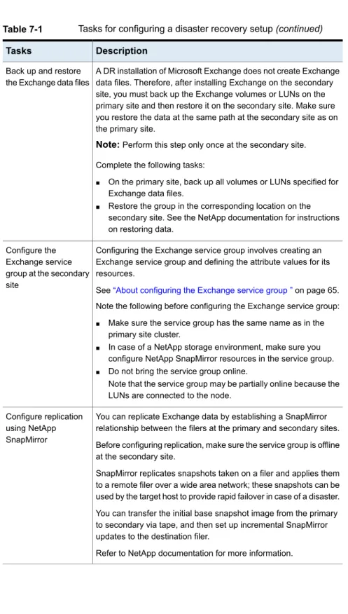
Setting up disaster recovery configuration ... 88
Configure replication using NetApp SnapMirror ... 91
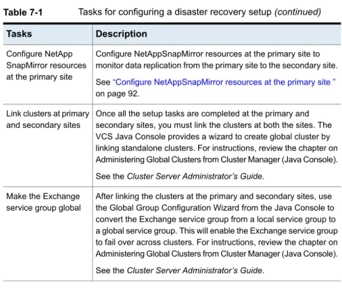
Configure NetAppSnapMirror resources at the primary site ... 92
About managing failover in a disaster recovery environment ... 93
Managing a successful remote failover ... 93
Managing failover in response to a network outage ... 93
About switching the service group back to the local cluster ... 94
Chapter 8
Removing the software
... 96About removing the software components ... 96
Remove Microsoft Exchange ... 97
Removing a node without removing Microsoft Exchange ... 97
Removing a node and removing Microsoft Exchange ... 98
Chapter 9
Troubleshooting the agents
... 100About troubleshooting VCS agents ... 100
VCS logging ... 100
VCS Cluster Configuration Wizard (VCW) logs ... 102
VCWsilent logs ... 102
NetApp agents error messages ... 103
Exchange Service agent error messages ... 104
Troubleshooting Microsoft Exchange uninstallation ... 106
About troubleshooting Exchange Setup Wizard issues ... 107
Exchange Setup Wizard may fail to rename the node ... 107
Exchange Setup Wizard may fail while moving the Exchange databases ... 108
Exchange database status appears as unknown ... 108
Appendix A
Resource type definitions
... 109About resource type definitions ... 109
Exchange Service agent ... 109
Exchange Service agent resource type definition ... 109
Dependency graph for an Exchange local cluster
configuration ... 111
Dependency graph for an Exchange disaster recovery configuration ... 112
Detail monitoring and agent behavior ... 113
Appendix B
Sample configuration
... 115About Exchange sample configurations ... 115
Sample configuration for an Exchange cluster (local cluster configuration) ... 115
Introducing the VCS
agents for Exchange and
NetApp
This chapter includes the following topics:
■ About the VCS agents for Exchange and NetApp ■ About VCS support for Exchange Server 2007
■ About the VCS application agent for Microsoft Exchange ■ About the VCS hardware replication agent for NetApp ■ How the agents make Microsoft Exchange highly available ■ Typical Exchange configurations in a VCS cluster
About the VCS agents for Exchange and NetApp
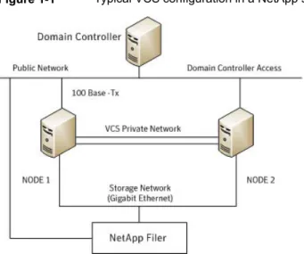
The Cluster Server (VCS) application agent for Exchange provides high availability to Microsoft Exchange Server. The VCS application agent for NetApp SnapMirror enables configuring NetApp filers over an iSCSI or Fibre Channel (FC) connection in a VCS cluster environment. Both agents work together to provide high availability and disaster recovery to Exchange Server in environments using NetApp filers for shared storage. The agents also support disaster recovery configurations set up using the VCS Global Cluster Option and NetApp SnapMirror for data replication. In a typical configuration, the agents are installed on each node in the cluster. The nodes are connected to the NetApp filers through a dedicated (private) storage
1
network. VCS nodes are physically attached to the NetApp filer via an ethernet cable supporting iSCSI or Fibre Channel (FC) as the transport protocol.
Figure 1-1illustrates a typical VCS cluster configuration in a NetApp storage environment.
Figure 1-1 Typical VCS configuration in a NetApp storage environment
For more information about the agents refer to their resource type definitions and attribute definitions.
See“About resource type definitions”on page 109.
About VCS support for Exchange Server 2007
VCS support for Exchange Server 2007 includes the following features:
■ High availability for Mailbox Server role only
High availability support for Exchange Server 2007 is available for the Mailbox Server role only. While installing Exchange, ensure that you do not install any other server role on the system on which you install the Mailbox Server role. If you have already installed the Mailbox Server role along with the other server roles on the same server, you will have to remove the other server roles before configuring Exchange in a VCS environment.
■ Exchange Management Shell in the virtual server context
The Exchange Management Shell provides a command-line interface that enables automation of administrative tasks for Exchange Server 2007. VCS provides a utility, the VCS Application Manager (VAM), that you can use to
launch the Exchange Management Shell under the context of the virtual server name.
On the SCC, under Tools, click VCS Application Manager to start VAM. Then double-click the Exchange resource to launch the Exchange Management Shell in the virtual server context.
You must run the Exchange Management Shell under the virtual server context if you wish to administer a clustered Exchange Server 2007 using cmdlets. Ensure that the Exchange service group is online before using the Exchange Management Shell in the virtual server context.
The Exchange Management Shell in the virtual server context is provided to run cmdlets for administering Exchange in a VCS cluster environment only. Do not run VCS executable files or commands in this shell.
Refer to the Exchange Server 2007 documentation for more information on server roles, the Exchange Management Shell and cmdlets.
About the VCS application agent for Microsoft
Exchange
The VCS application agent for Microsoft Exchange contains the Exchange Service agent that monitors Exchange services in a VCS cluster, brings them online, and takes them offline. The agent provides high availability for Exchange Server 2007 in a VCS cluster.
Note:High availability support for Microsoft Exchange Server 2007 is available for the Mailbox Server role only.
See“About the Exchange Service agent”on page 13.
About the Exchange Service agent
The Exchange Service agent brings the Exchange services online, monitors their status, and takes them offline.
Each Exchange Server service is configured as a VCS resource of type ExchService2007.
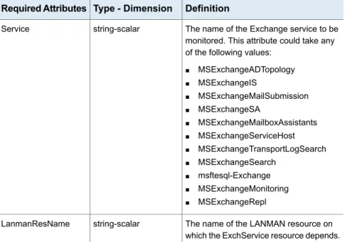
The Exchange services are as follows:
■ Microsoft Exchange AD Topology service (MSExchangeADTopology) This service provides Active Directory topology information to the Exchange services. If this service is stopped, most Exchange services are unable to start.
This service submits messages from the Mailbox Server to the Hub Transport Server.
■ Microsoft Exchange System Attendant (MSExchangeSA)
The Exchange component responsible for monitoring, maintenance and Active Directory lookup services, and ensuring that operations run smoothly.
In addition, you can also configure the agent to monitor the following optional services:
■ Microsoft Exchange Mailbox Assistants (MSExchangeMailboxAssistants) This service performs background processing of mailboxes in the Exchange store.
■ Microsoft Exchange Monitoring (MSExchangeMonitoring)
This service allows applications to call the Exchange diagnostic cmdlets (pronounced "command-lets").
■ Microsoft Exchange Replication Service (MSExchangeRepl)
This service provides replication functionality for Mailbox Server role databases and is used by Local Continuous Replication (LCR) and Cluster Continuous Replication (CCR).
■ Microsoft Exchange Search Indexer (MSExchangeSearch)
This service performs indexing of mailbox content, which improves the performance of content search.
■ Microsoft Exchange Service Host (MSExchangeServiceHost) This service provides a host for several Microsoft Exchange services.
■ Microsoft Exchange Transport Log Search (MSExchangeTransportLogSearch) This service provides remote search capability for Microsoft Exchange Transport log files.
■ Microsoft Search (msftesql-Exchange)
This service creates full-text indexes on content and properties of structured and semi-structured data to allow fast linguistic searches on the data.
Exchange Service agent functions
The Exchange Service agent functions are as follows:
Starts the configured Exchange service. Online
Stops the configured Exchange service. Offline
Determines the state of the configured Exchange service by querying the Service Control Manager (SCM).
The agent monitors and verifies the state of all the databases that are selected for detail monitoring. The agent behavior varies depending on how the attributes are configured.
See“Detail monitoring and agent behavior”on page 113.
Exchange Service agent state definitions
The Exchange Service agent state definitions are as follows:
Indicates that the configured Exchange service has started. Online
Indicates that the configured Exchange service has stopped. Offline
Indicates that the agent is unable to determine the state of the configured Exchange service.
Unknown
About the VCS hardware replication agent for
NetApp
The VCS hardware replication agent for NetApp provides failover support and recovery in environments employing NetApp filers for storage and NetApp SnapMirror for replication.
The agent monitors and manages the state of replicated filer devices and ensures that at a time only one system has safe and exclusive access to the configured devices.
The agent can be used in local clusters, single VCS replicated data clusters, and multi-cluster environments set up using the VCS Global Cluster Option (GCO). The VCS agents for NetApp are as follows:
■ NetAppFiler agent
■ NetAppSnapDrive agent
■ NetAppSnapMirror agent
About the NetApp Filer agent
The NetApp Filer agent monitors the state of the filer device. The agent is represented by the NetAppFiler resource type in VCS. NetAppFiler resources are persistent, meaning that they are not brought online or taken offline.
NetApp Filer agent function
The NetApp Filer agent function is as follows:
Performs the following tasks:
■ Verifies the state of the filer attached to the host by sending an ICMP ping command to the filer. If the filer does not respond, the agent reports the state of the filer as faulted.
■ Opens a filer connection and checks if ONTAPI version is supported by the filer. If the connection fails or the ONTAPI version is not supported, the agent reports the state as offline.
Monitor
The NetApp Filer agent resource type definition and attribute definitions are as follows. This information will assist you during the agent configuration.
NetAppFiler agent resource type definition
The NetApp Filer agent is configured as a resource of type NetAppFiler. type NetAppFiler (
static int MonitorInterval = 30
static i18nstr ArgList[] = { FilerName, StorageIP } static str Operations = None
str FilerName str StorageIP )
NetAppFiler agent attribute definitions
The following table describes the NetApp Filer agent attributes.
Description Attribute
DNS-resolvable name or IP address of the locally attached filer. Type and dimension: string-scalar
FilerName
The private storage IP address of the filer. Type and dimension: string-scalar StorageIP
About the NetApp SnapDrive agent
The NetApp SnapDrive agent monitors, connects, and disconnects filer volumes. You can configure the agent to use the iSCSI or the FC protocol.
NetApp SnapDrive agent functions
The NetApp SnapDrive agent functions are as follows:
Connects a virtual disk (LUN) using an iSCSI or an FC initiator. The agent presents the LUN as a locally-attached drive to the host. The agent also removes LUN-host mappings made before the online operation.
Online
Disconnects the virtual disk (LUN) from the host. Offline
Verifies that the specified virtual disk (LUN) is connected to the host. Monitor
Verifies that there is connectivitiy to the filer. It also checks that the VCS Helper service is running with the same privileges as the SnapDrive service.
Open
Attempts to forcibly disconnect a virtual disk (LUN). Clean
NetApp SnapDrive agent resource type definition and attribute definitions are as follows. This information will assist you during the agent configuration.
NetAppSnapDrive agent resource type definition
NetApp SnapDrive agent is configured as a resource of type NetAppSnapDrive. type NetAppSnapDrive (
static int MonitorInterval = 30 static int NumThreads = 1
static i18nstr ArgList[] = { FilerResName,
"FilerResName:FilerName", "FilerResName:StorageIP", VolumeName, ShareName, LUN, MountPath,
Initiator, InitiatorMonitorInterval } str FilerResName
str VolumeName str ShareName str LUN str MountPath str Initiator[]
int InitiatorMonitorInterval = 30 )
NetAppSnapDrive agent attribute definitions
Description Attribute
Name of the VCS NetAppFiler-type resource in the service group. Type and dimension: string-scalar
FilerResName
Name of the volume containing the virtual disk. Define the volume name in the same case as on the filer.
Type and dimension: string-scalar VolumeName
Name of the CIFS share containing the virtual disk. Type and dimension: string-scalar
ShareName
Name of the LUN (virtual disk) on the filer that is presented to the host for mounting. Define the LUN name in the same case as on the filer.
Type and dimension: string-scalar LUN
Drive letter to be assigned to the virtual disk. Type and dimension: string-scalar
MountPath
Name of iSCSI or FC initiator the host uses to connect virtual disks. You can retrieve this value from the Disk Management console. Type and dimension: string-vector
Initiator
About the NetApp SnapMirror agent
The NetApp SnapMirror agent monitors the replication state of filer devices. When a failover occurs, the agent reverses the direction of replication. The agent supports the replication modes supported by NetApp. The agent supports asynchronous, semi-synchronous, and synchronous modes of replication. You can set the mode of replication using the SyncMode agent attribute.
NetApp SnapMirror agent functions
If the state of the local filer device is SOURCE, the agent creates a lock file to indicate that the resource can come online. This effectively makes the devices writable for the application.
If the state of the local filer is SNAPMIRRORED, the agent attempts to reverse the direction of replication by changing the state of the local filer to SOURCE and that of the original source to SNAPMIRRORED. If the original source filer is down, the agent performs a mirror breakoff to enable local write access, if the filer is not already broken off. If the original source returns to life, you must resynchronize the data manually. The online function touches a lock file if read-write access is enabled successfully.
Online
Removes the lock file. The agent does not perform any filer operations because an offline entry point does not necessarily indicate an intention to give up the devices.
Offline
Verifies that the lock file exists. If the lock file exists, the monitor function reports the status of the resource as online. If the lock file does not exist, the monitor function reports the status of the resource as offline. Monitor
Removes the lock file thereby preventing potential concurrency violation if the group fails over to another node.
Note:The agent does not remove the lock file if the agent is started after anhastop -forcecommand.
Open
Removes the lock file. No filer operations are performed as taking the resource offline does not indicate a pending role swap.
Clean
Action function
Use the Action function to perform predefined actions on a resource. To perform an action on a resource, type the following command:
hares -action <SnapMirror_resname> <token> [-actionargs <arg1> ...] [-sys <system>] [-clus <cluster> ]
Table 1-1 Actions supported by NetAppSnapMirror agent
Description Token for Action
Resynchronises an original source volume with a broken-off volume. After synchronization, the original source volume becomes the target volume.
The broken-off volume was initially the target volume, but was broken off as a result of a take over.
fbsync
To synchronize volumes, type the following at the command prompt: hares -action SnapMirror_resname fbsync -sys node_name
Where,SnapMirror_resnamerepresents the name of the SnapMirror resource and
node_namerepresents the node on which the service group is online. Run the action for each SnapMirror resource.
You can also add custom actions for the agents. Refer to theCluster Server Agent Developer’s Guidefor more information.
NetApp SnapMirror agent resource type definition and attribute definitions are as follows. This information will assist you during the agent configuration.
NetAppSnapMirror agent resource type definition
NetApp SnapMirror agent is configured as a resource of type NetAppSnapMirror. type NetAppSnapMirror (
static keylist SupportedActions = { fbsync } static int MonitorInterval = 300
static int NumThreads = 1
static i18nstr ArgList[] = { FilerResName,
"FilerResName:FilerName", "FilerResName:StorageIP", VolumeName, SnapMirrorArguments, SnapMirrorSchedule, AppResName, VisibilityFrequency, SyncMode }
str FilerResName str VolumeName
str SnapMirrorArguments str SnapMirrorSchedule str AppResName
int VisibilityFrequency = 180 str SyncMode = async
NetAppSnapMirror agent attribute definitions
The following table describes the NetApp SnapMirror agent attributes.
Description Attribute
Name of the VCS NetAppFiler-type resource in the group. Type and dimension: string-scalar
FilerResName
Name of the filer volume containing the virtual disk. This is the volume that is to be mounted. Define the volume name in the same case as on the filer.
Type and dimension: string-scalar VolumeName
Specifies the SnapMirror arguments such as maximum transfer speed and restart mode.
The format for this attribute is: <RestartMode> MaxSpeed
MaxSpeed is an optional parameter. The RestartMode parameter can have the following values:
■ Always
■ Never
■ Default
Setting the RestartMode parameter value to default indicates schedule priority.
Default value of RestartMode parameter is ‘Default’ Example: Always MaxSpeed
Type and dimension: string-scalar SnapMirrorArguments
Specifies the schedule the destination uses for updating data. Do not assign a value for this attribute if you use SnapManager. The schedule is in the following format:
minute hour dayofmonth dayofweek Each field is separated by a space.
Refer to the NetApp documentation for more details on the rules for each of these schedule fields.
By default, this attribute does not have any value. Type and dimension: string-scalar
Description Attribute
Name of the resource configured to monitor the application being made highly available.
Type and dimension: string-scalar AppResName
Specifies the mode of replication for the mirror. This attribute can have the following values:
■ async: Indicates that the mirror should be configured in the asynchronous mode.
■ semi-sync: Indicates that the mirror should be configured in the semi-synchronous mode.
■ sync: Indicates that the mirror should be configured in the synchronous mode.
The default is async (asynchronous) mode. Type and dimension: string-scalar SyncMode
Specifies how often the source snapshot will be visible on the destination mirror. It controls the value of visibility_interval in the snapmirror.conf file.
The default value is 180 seconds.
This attribute is applicable only if the mirror is configured in synchronous or semi-synchronous mode.
Type and dimension: string-scalar VisibilityFrequency
How the agents make Microsoft Exchange highly
available
The VCS application agent for Microsoft Exchange detects an application failure if a configured Exchange service is not running or if a configured virtual server is not available. The NetApp agents ensure consistent data access to the node on which Exchange Server is running.
This section describes how the agents migrate Exchange Server to another node in local clusters and in global disaster recovery environments.
Local cluster configuration
When the Exchange agent detects an application or host failure, VCS attempts to fail over the Exchange service group to the next available system in the service group’s SystemList.
The NetApp agents connects the virtual disks (LUNs) containing Exchange data to the new node.
The configured Exchange services and virtual servers are started on the new node, thus ensuring continuous availability for Exchange data, including configured mailboxes.
Disaster recovery configuration
In a disaster recovery configuration, VCS first attempts to fail over the Exchange service group to a node in the local cluster. If all nodes in the local cluster are unavailable, or if a disaster strikes the site, VCS attempts to fail over the Exchange service group to the remote site.
This involves the following steps:
■ Connecting the virtual disks (LUNs) to the target hosts (using the NetAppSnapDrive agent)
■ Performing a mirror break, which enables write access to the target (using the NetAppSnapMirror agent)
■ Reversing the direction of replication by demoting the original source to a target, and begin replicating from the new source (using the NetAppSnapMirror agent)
■ Starting the Exchange services on the remote node (using the VCS agents for Exchange Server)
See“About managing failover in a disaster recovery environment ”on page 93.
Typical Exchange configurations in a VCS cluster
The VCS application agent for Microsoft Exchange supports the Active-Passive and the Any-to-Any configurations. It also supports the Disaster Recovery configuration.
Active-Passive failover configuration
An Active-Passive setup involves one to one failover capabilities. For example, if you have two nodes (SYSTEM1 and SYSTEM2), SYSTEM1 can fail over to SYSTEM2.
In an Active-Passive configuration, one or more Exchange virtual servers can exist in a cluster, but each server must be managed by a service group configured with a distinct set of nodes in the cluster.
In a typical two-node configuration, Microsoft Exchange and VCS application agent for Microsoft Exchange are installed on both nodes. The Exchange database is on
shared storage. The shared storage can be managed using Windows Logical Disk Management or the NetApp suite of products.
Figure 1-2illustrates an Active-Passive configuration.
Figure 1-2 Active-Passive fail over configuration
Any-to-Any failover configuration
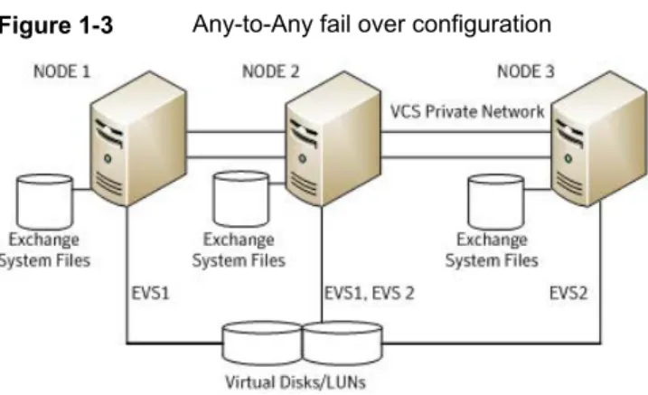
In an Any-to-Any configuration, each Exchange virtual server in the cluster can be configured in a separate service group. Each service group can fail over to any configured node in the cluster, provided that no other Exchange virtual server is online on that node. In other words, you must ensure that an Exchange service group does not fail over to a node on which another Exchange service group is online.
Figure 1-3illustrates and Any-to-Any configuration.
Figure 1-3 Any-to-Any fail over configuration
For example, consider a three-node cluster hosting two Exchange virtual servers, EVS1 and EVS2. The virtual servers are configured in VCS in two service groups such that nodes 1 and 2 host the EVS1 service group and nodes 2 and 3 host the
EVS2 service group. If node 1 (or node 3) fails, the service group containing the EVS resources is failed over to node 2.
Disaster recovery configuration
A Disaster Recovery (DR) configuration enables you to restore application data and services in the event of a catastrophic failure. A typical DR solution requires primary and secondary sites, and clusters within those sites. The cluster at the primary site provides data and services during normal operation, and the cluster at the secondary site provides data and services if the primary site fails.
Figure 1-4illustrates a Disaster Recovery configuation.
Figure 1-4 Disaster Recovery configuration
The illustration displays a disaster recovery configuration in a NetApp storage environment. In this case, the primary site is replicating its application data to the secondary site.
When a failure occurs, such as an earthquake that destroys the data center in which the primary site resides, the DR solution is activated. The data that was replicated to the secondary site is used to restore the application services to clients.
Installing the product and
configuring a VCS cluster
This chapter includes the following topics:
■ About installing the VCS agents
■ Configuring the cluster using the Cluster Configuration Wizard
About installing the VCS agents
Install Veritas InfoScale Availability on all the systems where you want to configure the application. During installation, the product installer installs the VCS agents required for making the applications highly available.
Refer to theVeritas InfoScale Installation and Upgrade Guidefor instructions. For the latest information about supported operating systems and software, see the Software Compatibility List at:
http://www.symantec.com/docs/TECH230643
Configuring the cluster using the Cluster
Configuration Wizard
After installing the software, set up the components required to run Cluster Server. The VCS Cluster Configuration Wizard (VCW) sets up the cluster infrastructure, including LLT and GAB, the user account for the VCS Helper service, and provides an option for configuring the VCS Authentication Service in the cluster. The wizard also configures the ClusterService group, which contains resources for notification and global clusters (GCO). You can also use VCW to modify or delete cluster configurations.
2
Note:After configuring the cluster you must not change the names of the nodes that are part of the cluster. If you wish to change a node name, run VCW to remove the node from the cluster, rename the system, and then run VCW again to add that system to the cluster.
Note the following prerequisites before you proceed:
■ The required network adapters, and SCSI controllers are installed and connected to each system.
To prevent lost heartbeats on the private networks, and to prevent VCS from mistakenly declaring a system down, Symantec recommends disabling the Ethernet auto-negotiation options on the private network adapters. Contact the NIC manufacturer for details on this process. Symantec recommends removing Internet Protocol TCP/IP from private NICs to lower system overhead.
■ Verify that the public network adapters on each node use static IP addresses (DHCP is not supported) and name resolution is configured for each node.
■ Symantec recommends that you use three network adapters (two NICs
exclusively for the VCS private network and one for the public network) per system. You can implement the second private link as a low-priority link over a public interface. Route each private NIC through a separate hub or switch to avoid single points of failure. Symantec recommends that you disable TCP/IP from private NICs to lower system overhead.
Note:If you wish to use Windows NIC teaming, you must select the Static Teaming mode. Only the Static Teaming mode is currently supported.
■ Use independent hubs or switches for each VCS communication network (GAB and LLT). You can use cross-over Ethernet cables for two-node clusters. GAB supports hub-based or switch network paths, or two-system clusters with direct network links.
■ Verify the DNS settings for all systems on which the application is installed and ensure that the public adapter is the first adapter in the Connections list. When enabling DNS name resolution, make sure that you use the public network adapters, and not those configured for the VCS private network.
■ The logged on user must have local Administrator privileges on the system where you run the wizard. The user account must be a domain user account.
■ The logged on user must have administrative access to all systems selected for cluster operations. Add the domain user account to the local Administrator group of each system.
■ If you plan to create a new user account for the VCS Helper service, the logged on user must have Domain Administrator privileges or must belong to the Domain Account Operators group.
■ When configuring a user account for the VCS Helper service, make sure that the user account is a domain user. The VCS High Availability Engine (HAD), which runs in the context of the local system built-in account, uses the VCS Helper Service user context to access the network. This account does not require Domain Administrator privileges.
■ Make sure the VCS Helper Service domain user account has "Add workstations to domain" privilege enabled in the Active Directory.
■ Verify that each system can access the storage devices and each system recognizes the attached shared disk.
Use Windows Disk Management on each system to verify that the attached shared LUNs (virtual disks) are visible.
■ If you plan to set up a disaster recovery (DR) environment, you must configure the wide-area connector process for global clusters.
■ If you are setting up a Replicated Data Cluster configuration, add only the systems in the primary zone (zone 0) to the cluster, at this time.
To configure a VCS cluster using the wizard
1
Start the VCS Cluster Configuration Wizard fromStart > All Programs > Symantec > Veritas Cluster Server > Configuration Tools > Cluster Configuration Wizardor, on Windows Server 2012 operating systems, from theAppsmenu in theStartscreen.2
Read the information on the Welcome panel and clickNext.3
On the Configuration Options panel, clickCluster Operationsand clickNext.4
On the Domain Selection panel, select or type the name of the domain in which the cluster resides and select the discovery options.To discover information about all systems and users in the domain, do the following:
■ ClearSpecify systems and users manually.
■ ClickNext.
Proceed to step8.
To specify systems and user names manually (recommended for large domains), do the following:
■ SelectSpecify systems and users manually.
Additionally, you may instruct the wizard to retrieve a list of systems and users in the domain by selecting appropriate check boxes.
■ ClickNext.
If you chose to retrieve the list of systems, proceed to step6. Otherwise, proceed to the next step.
5
On the System Selection panel, type the name of each system to be added, clickAdd, and then clickNext.Do not specify systems that are part of another cluster. Proceed to step8.
6
On the System Selection panel, specify the systems for the cluster and then clickNext.Do not select systems that are part of another cluster.
Enter the name of the system and clickAddto add the system to the Selected Systems list, or click to select the system in the Domain Systems list and then click the>(right-arrow) button.
7
The System Report panel displays the validation status, whether Accepted or Rejected, of all the systems you specified earlier. Review the status and then clickNext.Select the system to see the validation details. If you wish to include a rejected system, rectify the error based on the reason for rejection and then run the wizard again.
A system can be rejected for any of the following reasons:
■ System is not pingable.
■ WMI access is disabled on the system.
■ Wizard is unable to retrieve the system architecture or operating system.
■ Product is either not installed or there is a version mismatch.
8
On the Cluster Configuration Options panel, clickCreate New Clusterand then clickNext.9
On the Cluster Details panel, specify the details for the cluster and then clickNext.
Specify the cluster details as follows:
Type a name for the new cluster. Symantec recommends a maximum length of 32 characters for the cluster name. Cluster Name
Select a cluster ID from the suggested cluster IDs in the drop-down list, or type a unique ID for the cluster. The cluster ID can be any number from 0 to 65535.
Cluster ID
Note:If you chose to specify systems and users manually in step
4or if you share a private network between more than one domain, make sure that the cluster ID is unique.
From the drop-down list, select the operating system.
All the systems in the cluster must have the same operating system and architecture. For example, you cannot configure a Windows Server 2008 R2 system and a Windows Server 2012 system in the same cluster.
Operating System
Select the systems that you wish to configure in the cluster. Check theSelect all systemscheck box to select all the systems simultaneously.
The wizard discovers the NICs on the selected systems. For single-node clusters with the required number of NICs, the wizard prompts you to configure a private link heartbeat. In the dialog box, clickYesto configure a private link heartbeat.
Available Systems
10
The wizard validates the selected systems for cluster membership. After the systems are validated, clickNext.If a system is not validated, review the message associated with the failure and restart the wizard after rectifying the problem.
If you chose to configure a private link heartbeat in step9, proceed to the next step. Otherwise, proceed to step12.
11
On the Private Network Configuration panel, configure the VCS private network and then clickNext. You can configure the VCS private network either over the ethernet or over the User Datagram Protocol (UDP) layer using IPv4 or IPv6 network.Do one of the following:
■ To configure the VCS private network over ethernet, complete the following steps:
■ SelectConfigure LLT over Ethernet.
■ Select the check boxes next to the two NICs to be assigned to the private network. You can assign a maximum of eight network links.
Symantec recommends reserving two NICs exclusively for the private network. However, you could lower the priority of one of the NICs and use the low-priority NIC for both public and as well as private communication.
■ If there are only two NICs on a selected system, Symantec recommends that you lower the priority of at least one NIC that will be used for private as well as public network communication.
To lower the priority of a NIC, right-click the NIC and selectLow Priority
from the pop-up menu.
■ If your configuration contains teamed NICs, the wizard groups them as "NIC Group #N" where "N" is a number assigned to the teamed NIC. A teamed NIC is a logical NIC, formed by grouping several physical NICs together. All NICs in a team have an identical MAC address. Symantec recommends that you do not select teamed NICs for the private network.
The wizard configures the LLT service (over ethernet) on the selected network adapters.
■ To configure the VCS private network over the User Datagram Protocol (UDP) layer, complete the following steps:
■ SelectConfigure LLT over UDP on IPv4 networkorConfigure LLT over UDP on IPv6 networkdepending on the IP protocol that you wish to use. The IPv6 option is disabled if the network does not support IPv6.
■ Select the check boxes next to the NICs to be assigned to the private network. You can assign a maximum of eight network links. Symantec recommends reserving two NICs exclusively for the VCS private network.
■ For each selected NIC, verify the displayed IP address. If a selected NIC has multiple IP addresses assigned, double-click the field and choose the desired IP address from the drop-down list. In case of IPv4, each IP address can be in a different subnet.
The IP address is used for the VCS private communication over the specified UDP port.
■ Specify a unique UDP port for each of the link. ClickEdit Portsif you wish to edit the UDP ports for the links. You can use ports in the range 49152 to 65535. The default ports numbers are 50000 and 50001 respectively. ClickOK.
For each selected NIC, double-click the respective field in the Link column and choose a link from the drop-down list. Specify a different link (Link1 or Link2) for each NIC. Each link is associated with a UDP port that you specified earlier.
The wizard configures the LLT service (over UDP) on the selected network adapters. The specified UDP ports are used for the private network communication.
12
On the VCS Helper Service User Account panel, specify the name of a domain user for the VCS Helper Service.The VCS High Availability Engine (HAD), which runs in the context of the local system built-in account, uses the VCS Helper Service user context to access the network. This account does not require Domain Administrator privileges. Specify the domain user details as follows:
■ To specify an existing user, do one of the following:
■ ClickExisting userand select a user name from the drop-down list.
■ If you chose not to retrieve the list of users in step4, type the user name
■ To specify a new user, clickNew userand type a valid user name in the Create New User field and then clickNext.
Do not append the domain name to the user name; do not type the user name as Domain\user or user@domain.
■ In the Password dialog box, type the password for the specified user and clickOK, and then clickNext.
13
On the Configure Security Service Option panel, specify security options for the cluster communications and then clickNext.Do one of the following:
■ To use VCS cluster user privileges, clickUse VCS User Privilegesand then type a user name and password.
The wizard configures this user as a VCS Cluster Administrator. In this mode, communication between cluster nodes and clients, including Cluster Manager (Java Console), occurs using the encrypted VCS cluster administrator credentials. The wizard uses the VCSEncrypt utility to encrypt the user password.
The default user name for the VCS administrator isadminand the password ispassword. Both are case-sensitive. You can accept the default user name and password for the VCS administrator account or type a new name and password.
Symantec recommends that you specify a new user name and password.
■ To use the single sign-on feature, clickUse Single Sign-on. In this mode, the VCS Authentication Service is used to secure
communication between cluster nodes and clients by using digital certificates for authentication and SSL to encrypt communication over the public network. VCS uses SSL encryption and platform-based authentication. The VCS high availability engine (HAD) and Veritas Command Server run in secure mode.
The wizard configures all the cluster nodes as root brokers (RB) and authentication brokers (AB). Authentication brokers serve as intermediate registration and certification authorities. Authentication brokers have certificates signed by the root. These brokers can authenticate clients such as users and services. The wizard creates a copy of the certificates on all the cluster nodes.
14
Review the summary information on the Summary panel, and clickConfigure. The wizard configures the VCS private network. If the selected systems have LLT or GAB configuration files, the wizard displays an informational dialog box before overwriting the files. In the dialog box, clickOKto overwrite the files. Otherwise, clickCancel, exit the wizard, move the existing files to a different location, and rerun the wizard.The wizard starts running commands to configure VCS services. If an operation fails, clickView configuration log fileto see the log.
15
On the Completing Cluster Configuration panel, clickNextto configure the ClusterService group; this group is required to set up components for notification and for global clusters.To configure the ClusterService group later, clickFinish.
At this stage, the wizard has collected the information required to set up the cluster configuration. After the wizard completes its operations, with or without the ClusterService group components, the cluster is ready to host application service groups. The wizard also starts the VCS engine (HAD) and the Veritas Command Server at this stage.
16
On the Cluster Service Components panel, select the components to be configured in the ClusterService group and then clickNext.Do the following:
■ Check theNotifier Optioncheck box to configure notification of important events to designated recipients.
See“Configuring notification”on page 35.
■ Check theGCO Optioncheck box to configure the wide-area connector (WAC) process for global clusters.The WAC process is required for inter-cluster communication.
Configure the GCO Option using this wizard only if you are configuring a Disaster Recovery (DR) environment and are not using the Disaster Recovery wizard.
You can configure the GCO Option using the DR wizard. The Disaster Recovery chapters in the application solutions guides discuss how to use the Disaster Recovery wizard to configure the GCO option.
See“Configuring Wide-Area Connector process for global clusters”
on page 38.
Configuring notification
To configure notification
1
On the Notifier Options panel, specify the mode of notification to be configured and then clickNext.You can configure VCS to generate SNMP (V2) traps on a designated server and send emails to designated recipients in response to certain events.
2
If you chose to configure SNMP, specify information about the SNMP console and then clickNext.Do the following:
■ Click a field in theSNMP Consolecolumn and type the name or IP address of the console.
The specified SNMP console must be MIB 2.0 compliant.
■ Click the corresponding field in theSeveritycolumn and select a severity level for the console.
■ Enter an SNMP trap port. The default value is 162.
3
If you chose to configure SMTP, specify information about SMTP recipients and then clickNext.Do the following:
■ Type the name of the SMTP server.
■ Click a field in theRecipientscolumn and enter a recipient for notification. Enter recipients as [email protected].
■ Click the corresponding field in theSeveritycolumn and select a severity level for the recipient.
VCS sends messages of an equal or higher severity to the recipient.
■ Click the+icon to add fields; click the-icon to remove a field.
4
On the Notifier Network Card Selection panel, specify the network information and then clickNext.■ If the cluster has a ClusterService group configured, you can use the NIC resource configured in that service group or configure a new NIC resource for notification.
■ If you choose to configure a new NIC resource, select a network adapter for each node in the cluster.
The wizard lists the public network adapters along with the adapters that were assigned a low priority.
5
Review the summary information and choose whether you want to bring the notification resources online when VCS starts and clickConfigure.6
ClickFinishto exit the wizard.Configuring Wide-Area Connector process for global clusters
Configure the Wide-Area Connector process only if you are configuring a disaster recovery environment. The GCO option configures the wide-area connector (WAC) process for global clusters. The WAC process is required for inter-cluster
communication. Configure the GCO Option using this wizard only if you are configuring a Disaster Recovery (DR) environment and are not using the Disaster Recovery wizard.
You can configure the GCO Option using the DR wizard. The Disaster Recovery chapters in the application solutions guides discuss how to use the Disaster Recovery wizard to configure the GCO option.
To configure the wide-area connector process for global clusters
1
On the GCO Network Selection panel, specify the network information and then clickNext.If the cluster has a ClusterService group configured, you can use the IP address configured in the service group or configure a new IP address.
Do the following:
■ To specify an existing IP address, selectUse existing IP resourceand then select the IP address from the drop-down list.
■ To use a new IP address, do the following:
■ In case of IPv4, selectIPV4and then enter the IP address and associated subnet mask. Make sure that the specified IP address has a DNS entry.
■ In case of IPv6, selectIPV6and select the IPv6 network from the drop-down list.
The wizard uses the network prefix and automatically generates a unique IPv6 address that is valid on the network.
The IPv6 option is disabled if the network does not support IPv6.
The wizard lists the public network adapters along with the adapters that were assigned a low priority.
2
Review the summary information and choose whether you want to bring the WAC resources online when VCS starts and then clickConfigure.Installing Microsoft
Exchange
This chapter includes the following topics:
■ About installing Exchange 2007 in a VCS environment ■ Prerequisites for installing Exchange in a VCS environment ■ Managing storage using NetApp filer
■ Managing storage using Windows Logical Disk Manager ■ Installing Exchange 2007 on the first node
■ Moving Exchange databases to shared storage ■ Installing Exchange 2007 on additional nodes
About installing Exchange 2007 in a VCS
environment
This chapter describes how to install Exchange Server and configure a VCS cluster. If you already have a standalone Exchange Server setup and you want to configure it for high availability.
Prerequisites for installing Exchange in a VCS
environment
Prerequisites for installing Exchange in a VCS environment are as follows:
3
■ Verify InfoScale Availability is installed on the node.
■ Verify you have configured a VCS cluster using VCS Cluster Configuration
Wizard (VCW).
■ Verify the DNS and Active Directory Services are available. Make sure that a
reverse lookup zone is created in the DNS.
Refer to Microsoft Exchange documentation for instructions on creating a reverse lookup zone.
■ Symantec recommends that the Dynamic Update option for the DNS server be
set to "Secure Only."
■ Verify the DNS settings for all systems on which Microsoft Exchange will be installed.
See“Verifying DNS settings for Exchange hosts ”on page 43.
■ VCS requires Microsoft Exchange to be installed on the same local drive on all nodes. For example if you install Exchange on drive C of one node, installations on all other nodes must be on their respective C drives. Make sure that the same drive letter is available on all nodes and has adequate space for the installation.
■ In a NetApp storage environment, while configuring Exchange on additional
nodes, if there are any other LUNs (not necessarily for Exchange) mounted on the node, ensure that you unmount them before you perform the Exchange post-installation tasks on that node.
■ Exchange 2007 installer requires that the Exchange database drive should be mounted on the node when installing Exchange 2007 in RecoverServer install mode. After the Exchange installation is complete, you must unmount the Exchange database LUN before you perform the post-installation tasks on the node.
■ If using iSCSI, verify that the Microsoft iSCSI Initiator is configured to establish
a non-persistent connection between the NetApp filer and the cluster nodes. Set the "Automatically restore this connection when the system boots" option to False.
Symantec recommends that you use non-persistent iSCSI connections to avoid service group concurrency violation issue in a NetApp storage environment. See the Microsoft documentation for instructions.
■ If using FC, verify that you install the NetApp FCP Attach Kit or Windows Host Utilities on all the cluster nodes.
Refer to the NetApp documentation for more information.
■ Symantec recommends that you create volumes or LUNs (virtual disks), one each for the following:
■ Registry replication information
■ Transaction logs for the first storage group
■ Verify that the volume or LUN created to store the registry replication information is mounted on the node where you install Microsoft Exchange and unmounted from other nodes in the cluster.
■ In an IPv6 environment, the Lanman agent relies on the DNS records to validate the virtual server name on the network. If the virtual servers configured in the cluster use IPv6 addresses, you must specify the DNS server IP, either in the network adapter settings or in the Lanman agent’s AdditionalDNSServers attribute.
Privileges for installing Exchange
You must have the following privileges:
■ The logged-on user must be a domain user.
■ The logged-on user must be logged on with either the Exchange Organization Administrator role or have been delegated the permission to install the server through Setup’s server provisioning process.
■ The logged-on user must be a part of the Account Operators group in the domain.
If the logged-on user account is not a Domain Administrator then the Exchange Servers group must be managed by the logged-on user account or the VCS Helper Service user account.
■ The logged-on user must be a member of the local Administrators group on all nodes where you are installing Microsoft Exchange and must have write permissions for objects corresponding to these nodes in the Active Directory.
■ Either the logged-on user or the VCS Helper Service domain user account must
have write permissions on the DNS server to perform DNS updates.
■ Make sure the VCS Helper Service domain user account has "Add workstations to domain" privilege enabled in the Active Directory.
■ If a computer object corresponding to the Exchange virtual server exists in the
Active Directory, you must have delete permissions on the object.
■ The same user, or a user with the same privileges must perform the
pre-installation, installation, and post-installation tasks for Microsoft Exchange.
Verifying DNS settings for Exchange hosts
To verify the DNS settings for Exchange hosts
1
Open the Network Connections applet in Control Panel.2
Double-click the adapter.When enabling DNS name resolution, make sure that you use the public network adapters, and not those configured for the VCS private network.
3
From the Local Area Connection Status window, clickProperties.4
On the General tab, check theInternet Protocol (TCP/IP)check box and then clickProperties.5
Select theUse the following DNS server addressesoption.6
Verify that the correct values for the DNS server IP address and domain name are entered and then clickAdvanced.7
On the DNS tab, make sure theRegister this connection’s address in DNScheck box is selected.
8
Make sure the correct domain suffix is entered in the DNS suffix for this connection field.Configuring Microsoft iSCSI initiator
The Microsoft iSCSI initiator enables communication between Windows systems and NetApp Filers. The initiator uses the iSCSI protocol to present the filer volume as a local block device to the system.
Perform the following steps after you have mounted the required LUNs using the NetApp SnapDrive agent.
To configure Microsoft iSCSI initiator on a Windows Server 2008 system:
1
Start the Microsoft iSCSI initiator.2
On the Target Portals dialog box, specify the DNS name or IP address for the NetApp Filer.3
On the Favorite Targets tab, remove the corresponding entry.4
Click OK.Managing storage using NetApp filer
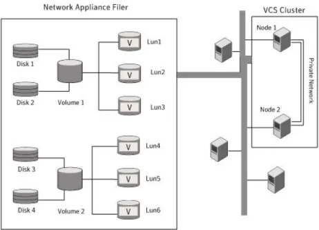
NetApp manages data by creating volumes on physical disks. These volumes can further be divided into LUNs (Logical Unit Numbers). The LUNs are accessible from the cluster nodes, provided the nodes have Microsoft iSCSI Initiator and NetApp SnapDrive installed. However, if you plan to use Fibre Channel (FC) for connecting
the LUNs, ensure that filer is connected to the nodes and the LUNs are shared between all the cluster nodes.
Refer to the NetApp documentation for more information.
Figure 3-1illustrates a typical VCS cluster in a NetApp storage environment.
Figure 3-1 VCS cluster in a NetApp storage environment
Symantec recommends that you create separate LUNs (virtual disks) for the following:
■ Exchange database
■ Transaction logs for the first storage group
■ Registry replication information
If the Exchange database and registry replication files are configured on the same volume, there are potential chances of data corruption after you upgrade Exchange with the latest service pack.
These LUNs must be accessible from all cluster nodes.
Perform the following tasks to create LUNs on the NetApp filer and to make them accessible from cluster nodes:
■ Add the filer storage system to the SnapDrive Storage System Management snap-in on the cluster nodes.
■ Create volumes on the NetApp filer.
■ Share the volumes.
■ Create LUNs or virtual disks on the shared volumes.
Refer to NetApp documentation for instructions on performing these tasks.
Connecting virtual disks to the cluster node
Once the virtual disks are created on the NetApp filer, they must be connected (if not connected already) to the cluster nodes using NetApp SnapDrive.
To connect virtual disks to the cluster node
1
On the cluster node where you want to connect the LUN, launch the Computer Management MMC fromStart > All Programs > Administrative Tools > Computer Managementor, on Windows Server 2012 operating systems, clickAdministrative Toolsfrom theStartscreen.
2
From the left pane, expandStorageand double-clickSnapDrive.3
Right-clickDisksand then clickConnect Diskto launch the Connect Disk wizard.4
ClickNexton the Welcome page.5
Specify the path of the virtual disk that you wish to connect to the cluster node and then clickNext.6
SelectDedicatedas the Virtual Disk Type and then clickNext.7
ClickAssign a Drive Letterand then choose a drive letter from the drop-down list.8
On the Select Initiator panel, specify the initiator(s) for the virtual disk and then clickNext.9
On the igroup Management Type panel, choose the option that allows SnapDrive to perform igroup management automatically and then clickNext.10
ClickFinishto begin connecting the specified virtual disk to the cluster node.Disconnecting virtual disks from the cluster nodes
To disconnect virtual disks
1
On the cluster node where you want to disconnect the LUNs, launch the Computer Management MMC fromStart > All Programs > Administrative Tools > Computer Managementor, on Windows Server 2012 operating systems, clickAdministrative Toolsfrom theStartscreen .2
From the left pane, expandStorageand double-clickSnapDrive.3
Double-clickDisksto see the LUNs that are connected to the node.4
Right-click the LUN you want to disconnect and then clickDisconnect Disk.5
In the Disconnect Disk alert box, clickOK.Managing storage using Windows Logical Disk
Manager
If your configuration uses shared disks and volumes that are managed using Windows Logical Disk Manager (LDM), use the VCS Mount and DiskReservation (DiskRes) agents. If you use LDM to manage non-shared local storage, use the VCS Mount and NativeDisks agents.
Before configuring the storage, review the resource types and attribute definitions of these VCS storage agents (Mount, DiskRes, NativeDisks) described in theCluster Server Bundled Agents Reference Guide.
The following restrictions apply for storage managed using LDM:
■ Mount, DiskRes, and NativeDisks agents are supported on VCS for Windows only. These agents are not supported if the storage is managed using Storage Foundation (SFW).
■ If you are using shared storage, your storage devices must be configured to use SCSI-2 disk reservations. SCSI-3 is not supported.
SCSI support is not required if you are using non-shared storage.
■ LDM support is not applicable for Disaster Recovery configurations. Currently only HA configurations are supported.
Symantec recommends that you create separate volumes for the following:
■ Exchange database
■ Transaction logs for the first storage group ■ Registry replication information
If the Exchange database and registry replication files are configured on the same volume, there are potential chances of data corruption after you upgrade Exchange with the latest service pack.