100 Gb/s Ethernet/OTN using 10X10
MSA Optical Modules
David Lewis, JDSU
Jim Tavacoli, Santur
Scott Kipp, Brocade
Bikash Koley, Google
Vijay Vusirikala, Google
Executive Summary:
10X10 MSA based optical modules provide a low-cost, power-efficient,
multi-sourced and interoperable solution that will accelerate the transition to 100Gbps
technologies. The 10X10 MSA leverages mature 10G technologies to provide the
lowest cost solution in terms of bandwidth per meter and bandwidth per watt.
This white paper summarizes the drivers and design considerations behind the
10X10 MSA from various perspectives in the networking value chain – large
end-users, system vendors and component vendors.
Introduction
The dramatic growth in innovative, bandwidth-intensive applications coupled with the
migration from local compute/storage model to a cloud computing paradigm is driving the need for 100 Gbps interconnect solutions. The key impediment to accelerated adoption of 100
Gigabit Ethernet has been the high-cost and high-power footprint of the IEEE standardized 10 km client optical modules (100GBASE-LR4). Optical modules based on the 10X10 MSA address these shortcomings of the LR4 optical module and provide a multi-sourced, interoperable solution that is compatible with the CFP form-factor.
This white paper describes the drivers and technical underpinnings behind the 10X10 MSA optical modules and provides detailed perspectives from large end users, system vendors as well as component vendors.
Large Data Center Operator Perspective: Cost and Power Efficient
Interconnect Scaling
As computation and storage continue to move from desktops to large internet services or cloud services, computing platforms running such services are transforming into warehouse-scale computers (WSCs). These WSCs provide a ubiquitous, interconnected compute platform as a shared resource for many distributed services, and therefore are very different from the traditional rack of collocated servers in a data-center [1]. Interconnecting such WSCs in a cost-effective yet scalable way is a unique challenge that needs to be addressed. Cost-cost-effective and power-efficient 100 Gigabit Ethernet interfaces, that support more than 150 meters reach, are instrumental in scaling the interconnection within and between these WSCs.
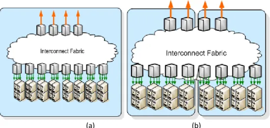
Figure 1 shows a common architecture of a WSC. A set of commodity servers are arranged into racks and interconnected through a Top Of Rack (TOR) switch. Rack switches are connected to cluster switches which provide connectivity between racks and form the cluster-fabrics for warehouse-scale computing.
Figure 1 - Typical elements in a Warehouse Scale Computer
Ideally, the intra-datacenter switching fabric should have sufficient bi-sectional bandwidth to accommodate non-blocking connection from every server to every other server in a datacenter. Non-blocking connections between servers enable applications that do not require location awareness within a WSC infrastructure. However, such a design would be prohibitively expensive. More commonly, interconnections are aggregated with hierarchies of distributed switching fabrics with an over-subscription factor for communication between racks (Fig. 2) [2]. In order to scale the cross-sectional bandwidth at various layers of the hierarchy, the introduction of higher-speed optical interfaces is a necessary, provided these interfaces follow the following four rules [2]:
1. 10x speed @ 4x power dissipation 2. 10x speed @ 4x cost
3. Compatible with deployed fiber-infrastructure 4. Supported by multiple sources
(a) (b)
Figure 2 - Hierarchies of intra-datacenter cluster-switching interconnect fabrics (a) within a single building (b) across multiple buildings
At the initial phase of introduction, the higher-speed interfaces must not dissipate more power and cost more on a per-Gbps basis compared to the previous generation lower-speed
interfaces. With maturity, the interfaces need to follow the 10x @ 4x rule for both cost and power dissipation. This is illustrated by the speed with which 10Gbps optical interfaces became the mainstay for WSC interconnects with the introduction of SFP+ (10x speed for 1.5x
power/cost compared to 1GbE interfaces).
100 Gbps optical interfaces need to follow the same scaling rule in-order to get wide-acceptance in very large WSC deployments. Unfortunately, neither of the two main optical interface standards defined in IEEE802.3ba for 100GbE client interfaces (100GBASE-SR10 and 100GBASE-LR4) meets all of the four requirements outlined above. 100GBASE-SR10 suffers from requiring incompatible fiber-plant in the data-centers (expensive multi-mode ribbon-fibers and MPO connectors) while 100GBASE-LR4 CFP interfaces currently scale to 10x speed for 100x cost and 17x power-dissipation compared to 10G SFP+ optical interfaces. It is necessary to define a solution today that is compatible with single-mode optical fiber plant, has at-least 2km reach and meets 10x speed for 10x power/cost scaling TODAY with a clear path towards 4x cost and power in 2012. This sets the target for the first-generation modules to no more than 15W power-dissipation and cost-parity on a gigabit per-second basis with equivalent 10G interfaces. The second generation modules need to meet 6W power consumption target in a smaller-form-factor by 2012.
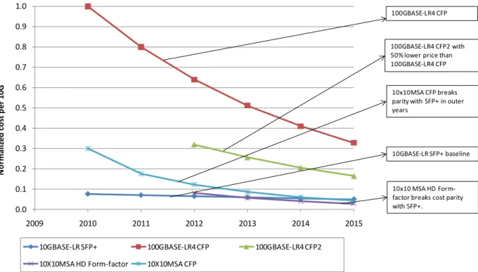
The 10X10 MSA has been established to define a 100Gbps interface standard to meet these requirements. First-generation 10X10 CFP modules have a considerable cost advantage over 100GBASE-LR4 CFP modules as shown in Figure 3. The second generation 10X10 module that is
being defined and referred to as the 10X10 High Density (HD) Form-factor module is expected to have a considerable cost advantage compared to the second generation 100GBASE-LR4 CFP2 module. The 10x10 HD form-factor modules are the only 100Gbps interface solution capable of meeting the need of very-large WSC interconnects with the right scaling factor in the next three to five years.
Figure3 - 100Gbps client interface price evolution normalized to existing 10Gbps module pricing
System Vendor Perspective : Low Cost, Low Power and CFP Compatibility
The key benefits from the system vendor perspective are that the 10X10 MSA based optical link provides better link distance than 100GBASE-SR10, is lower cost and power than 100GBASE-LR4 and fits in the CFP form factor. Many customers need to go farther than the 100 meters of 100GBASE-SR10 but cannot afford the high cost of 100GBASE-LR4. The 10X10 module in the CFP form factor can easily replace the 100GBASE-LR4 CFP and meet the needs of most users at a much lower cost.
0.0 0.1 0.2 0.3 0.4 0.5 0.6 0.7 0.8 0.9 1.0
2009 2010 2011 2012 2013 2014 2015
N o rma li zed c o st p er 1 0 G
10GBASE-LR SFP+ 100GBASE-LR4 CFP 100GBASE-LR4 CFP2
10X10MSA HD Form-factor 10X10MSA CFP
10x10 MSA HD Form-factor breaks cost parity with SFP+.
10GBASE-LR SFP+ baseline 10x10MSA CFP breaks parity with SFP+ in outer years
100GBASE-LR4 CFP2 with 50% lower price than 100GBASE-LR4 CFP 100GBASE-LR4 CFP
1. Longer Link Distances
The 10X10-2km link fills a gap between the 100m reach of 100GBASE-SR10 links on Optical Multimode 3 (OM3) fibers and the 10km reach of 100GBASE-LR4 Single Mode Fiber (SMF) links. While 100 meter links fulfill the needs of many applications, the link distances easily exceed 100 meters in large data centers. A quick analysis shows that the link lengths of data centers with over 50,000 square feet (sqft) will have a need for links longer than 100 meters.
The maximum link length depends on the size of the data center. A simple geometric study shows that a moderately sized data center of 50,000 sqft could have links as long as 150 meters. Based on the formulas in Figure 4, a 75,000 sqft data center would be about 274’ wide and long. If links are assumed to run orthogonal paths, then the link length would be 548’ long in two dimensions. The data in Table 1 assumes that 25’ of additional link length known as slack is used to run the cable up and down and through racks. With these assumptions, the link length is 573’ or 174 meters. This is longer than the longest link supported by 100GBASE-SR10 that is 150 meters on OM4 fiber, so the end user must use 100GBASE-LR4 or the 10X10 solution.
Table 1: Link Length Comparison
The cabling costs for multi-mode fiber links based on 100GBASE-SR10 are considerably more expensive than for the single-mode links. For 100GBASE-LR10 solutions, 24 fiber ribbons are required to connect the modules while the 10X10 module and the 100GBASE-LR4 modules only require duplex single-mode fibers. Since 24 fiber ribbons cost tens of dollars more per foot than duplex single-mode fiber, the cabling cost difference of a 200’ link can be several
thousands of dollars. The 10X10 solution offers lower cabling costs than the 100GBASE-SR10 solution.
If the end user requires the 10km link of 100GBASE-LR4, some vendors support a 10km version of the 10X10 solution. Modules that go beyond the 2km 10X10 specification but still meet the receiver requirements of the 10X10 MSA are considered compliant to the 10X10 MSA.
Data Center Size (sq ft)
Data Center Size
(sq m)
Square Data Center Longest Cable Length (m)
Rectangular Data Center Longest Cable Length (m)
10,000 918 68 72
30,000 2,755 113 119
50,000 4,591 143 151
75,000 6,887 174 184
100,000 9,183 199 211
125,000 11,478 222 235
150,000 13,774 242 257
200,000 18,365 279 295
300,000 27,548 340 360
2. Lower Cost
If a user has to go beyond 150 meters, then they must consider a single-mode solution and the cost difference is even larger between the 10X10 solution and the 100GBASE-LR4 solution. As shown on this blog “How to Save $100,000 with a 10X10 Link”, the end user cost of the 100GBASE-LR4 CFP module can be well over $100,000. Since the 10X10 CFP modules are less than half the price of the 100GBASE-LR4 module, the end user can save over $100,000 on a link that uses two modules.
3. Lower Power
The 100GBASE-LR4 CFP module consumes about 21 Watts of power while the 10X10 CFP module consumes about 14 Watts of power. The 10X10 link saves about 7 Watts of power or 33% of the power used by the modules when compared to the 100GBASE-LR4 link. The power consumed by the module must be cooled and one rule of thumb is that an equal amount of power is consumed to cool the data center for each Watt of equipment consumption.
4. CFP Compatibility
Another benefit from the system provider perspective is that the 10X10 module is compliant to the CFP specification and hence can be used in the same slot as the 100GBASE-LR4 solution. The 10X10 CFP module uses the same CAUI electrical interface, MDIO management interface and single-mode fiber as the 100GBASE-LR4 solution. The 10X10 module is thus
interchangeable with a 100GBASE-LR4 module but provides a lower cost and lower power solution.
Optical Component Vendor Perspective : Mature Technology with Lower
Cost Points and Future Compatibility
With the publication of 100 Gigabit Ethernet standards in IEEE802.3ba and the adoption of the OTU4 rate of 112 Gbps to directly carry 100 GbE, a new generation of optical modules have been developed for these 100 Gbps applications. First to be available is the CFP form-factor (Fig. 5), developed by the CFP MSA (http://cfp-msa.org), and intended for implementation of 40G and 100G standards up to and including 100GBASE-ER4 (40 km). The CFP electrical connector has pins for 10 lanes in each direction and is hence able to support 10-wide standards including 100GBASE-SR10 and 10X10 MSA implementations.
Figure 5 - CFP Module
An appendix in the 10X10 MSA technical specification provides details of the electrical connections and MDIO NVR entries applicable to implementation of 10X10 in the CFP form factor.
CFP 10X10 modules began shipping in 2010. Based on readily available 10 Gbps DFB laser arrays and PIN-TIA circuits, these modules will be the low cost leader until higher density modules appear.
The CFP form-factor is large enough to handle the electrical interface signals and power
consumption requirements of multiple 40 and 100 Gb/s standards up to and including the 40km 100GBASE-ER4. There are increasing user demands for higher density 100 Gb/s modules
however and there is industry activity to standardize modules with footprints significantly smaller than the CFP. In order to achieve this smaller size, efforts are underway to miniaturize the optical subassemblies, utilize low power laser drivers and optical receivers, and to use non-retimed electrical interfaces such as CPPI which has the retimers outside of the optical module. Higher density versions of 10X10 MSA modules will become available in 2012 and are expected to enable large data centers to move to 100 Gb/s ports.
Conclusion
10X10 MSA optical modules meet the key criteria that various industry stakeholders (end-users, system vendors and component manufacturers) are looking for to enable the wide spread adoption of 100 Gbps technologies. 10X10 optical modules provide (a) the low-cost and power efficiency that is lacking in currently standardized 100GBASE-LR4, (b) the reach and single-mode duplex fiber capability that is lacking in 100GBASE-SR10, (c) the form-factor compatibility with
CFP that makes system design simpler, and (d) compatibility with future higher-density form-factors.
Equally importantly, 10X10 MSA enjoys broad support from a wide cross section of industry representatives with a very significant participation from major end-users and system vendors. This direct input from end-users for the definition of the technical specifications, eliminates the “Lost in Translation” issues that has plagued some past form-factors and optical PMDs and helps craft the most targeted and optimal solution.
For more information on the 10X10 solutions, please visit www.10X10msa.org.
References:
1. L.A. Barroso and U. Hölzle. The Datacenter as a Computer – an Introduction to the Design of Warehouse-Scale Machines, Morgan & Claypool Publishers,
2009. http://www.morganclaypool.com/doi/pdf/10.2200/S00193ED1V01Y200905CAC006
2. B, Koley, “Requirements for Data Center Interconnects,” paper TuA2, 20th Annual
Workshop on Interconnections within High Speed Digital Systems, Santa Fe, New Mexico, 3 – 6 May 2009.