AN2594
Application note
EEPROM emulation
in STM32F10x microcontrollers
Introduction
Many applications require EEPROM (electrically erasable programmable read-only memory) for non-volatile data storage. For low-cost purposes, the STM32F10x devices do not use EEPROM. Instead, they implement EEPROM emulation using the embedded Flash memory.
This application note explains the differences between external EEPROM and embedded Flash memory, and it describes a software method for emulating EEPROM using the on-chip Flash memory of the STM32F10x devices.
This document also focuses on some embedded aspects in emulated EEPROM data storage, that the reader is assumed to know.
Glossary
Low-density devices are STM32F101xx, STM32F102xx and STM32F103xx microcontrollers where the Flash memory density ranges between 16 and 32 Kbytes.
Medium-density devices are STM32F10x and STM32F103xx microcontrollers where the Flash memory density ranges between 32 and 128 Kbytes.
High-density devices are STM32F10x and STM32F103xx microcontrollers where the Flash memory density ranges between 256 and 512 Kbytes.
Contents AN2594
Contents
1
Embedded Flash memory versus EEPROM: main differences . . . 5
1.1
Difference in write access time . . . 5
1.2
Difference in writing method . . . 6
1.3
Difference in erase time . . . 6
2
Implementing EEPROM emulation . . . 7
2.1
Principle . . . 7
2.1.1 Application example . . . 8
2.1.2 EEPROM software description . . . 8
3
Embedded application aspects . . . 11
3.1
Data granularity management . . . 11
3.1.1 Programming on a word-by-word basis . . . 11
3.1.2 Programming on a byte-by-byte basis . . . 11
3.2
Wear leveling: Flash memory endurance improvement . . . 11
3.2.1 Wear-leveling implementation example . . . 11
3.3
Page header recovery in case of power loss . . . 12
3.4
Cycling capability . . . 13
AN2594 List of tables
List of tables
Table 1. Differences between embedded Flash memory and EEPROM . . . 5
Table 2. Status combinations and actions to be taken . . . 13
Table 3. Maximum number of variables stored in emulated EEPROM (with 10 000 cycles) . . . 14
List of figures AN2594
List of figures
Figure 1. Header status switching between page0 and page1 . . . 7
Figure 2. EEPROM variable format . . . 8
Figure 3. Data update flow . . . 8
Figure 4. WriteVariable flowchart . . . 10
AN2594 Embedded Flash memory versus EEPROM: main differences
1
Embedded Flash memory versus EEPROM: main
differences
Electrically erasable programmable read-only memory (EEPROM) is a key component of many embedded applications that require non-volatile storage of data updated with a byte or word granularity during run time.
On the other hand, the microcontrollers used in those systems are each time more often based on embedded Flash memory. To eliminate components, save silicon space and reduce system cost, the STM32F10xxx Flash memory may be used instead of EEPROM for simultaneous code and data storage.
Unlike Flash memory, however, external EEPROM does not require an erase operation to free up space before data can be rewritten. Hence a special software management is required to store data into embedded Flash memory.
Obviously the emulation software scheme depends on many factors, including the EEPROM reliability, the architecture of the Flash memory used, and the product requirements.
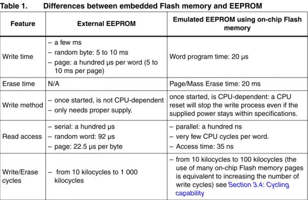
The main differences between embedded Flash memory and external serial EEPROM are generic to any microcontroller that use the same Flash memory technology (it is not specific to the STM32F10xxx family products). The major differences are summarized in Table 1.
1.1
Difference in write access time
As Flash memories have a shorter write access time, critical parameters can be stored faster in the emulated EEPROM than in an external serial EEPROM, thereby improving data storage.
Table 1. Differences between embedded Flash memory and EEPROM
Feature External EEPROM Emulated EEPROM using on-chip Flash memory
Write time
– a few ms
– random byte: 5 to 10 ms
– page: a hundred µs per word (5 to 10 ms per page)
Word program time: 20 µs
Erase time N/A Page/Mass Erase time: 20 ms
Write method – once started, is not CPU-dependent – only needs proper supply.
once started, is CPU-dependent: a CPU reset will stop the write process even if the supplied power stays within specifications.
Read access
– serial: a hundred µs – random word: 92 µs – page: 22.5 µs per byte
– parallel: a hundred ns
– very few CPU cycles per word. – Access time: 35 ns
Write/Erase cycles
– from 10 kilocycles to 1 000 kilocycles
– from 10 kilocycles to 100 kilocycles (the use of many on-chip Flash memory pages is equivalent to increasing the number of write cycles) see Section 3.4: Cycling capability
Embedded Flash memory versus EEPROM: main differences AN2594
1.2
Difference in writing method
One of the major differences between external EEPROM and emulated EEPROM for embedded applications is the writing method.
● Standalone external EEPROM: once started by the CPU, the writing of a word cannot be interrupted by a CPU reset. Only supply failure will interrupt the write process, so properly sizing the decoupling capacitors can secure the complete writing process inside a standalone EEPROM.
● Emulated EEPROM using an embedded Flash memory: once started by the CPU, the write process can be interrupted by a power failure and by a CPU reset. This difference should be analyzed by system designers to understand the possible impact(s) on their applications and to determine a proper handling method.
1.3
Difference in erase time
The difference in erase time is the other major difference between a standalone EEPROM and emulated EEPROM using embedded Flash memory. Unlike Flash memories,
EEPROMs do not require an erase operation to free up space before writing to them. This means that some form of software management is required to store data in Flash memory. Moreover, as the erase process of a block in the Flash memory takes a few milliseconds, power shut-down and other spurious events that might interrupt the erase process (for example a reset) should be considered when designing the Flash memory management software. To design a robust Flash memory management software it is necessary to have a deep understanding of the Flash memory erase process.
AN2594 Implementing EEPROM emulation
2 Implementing
EEPROM
emulation
2.1 Principle
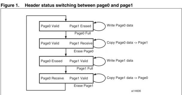
EEPROM emulation is performed in various ways by considering the Flash memory limitations and product requirements. The approach detailed below requires at least two Flash memory pages of identical size allocated to non-volatile data. One that is initially erased, and offers byte-by-byte programmability; the other that is ready to take over when the former page needs to be garbage-collected. A header field that occupies the first 16-bit half word of each page indicates the page status.
The header field is located at the base address of each page and gives the page status information.
Each page has three possible states:
● ERASED: the page is empty.
● RECEIVE_DATA: the page is receiving data from the other full page.
● VALID_PAGE: the page contains valid data and this state does not change until all valid data are completely transferred to the erased page.
Figure 1 shows how the page statuses change with respect to each other.
Figure 1. Header status switching between page0 and page1
Generally, when using this method, the user does not know in advance the variable update frequency.
The software and implementation described in this document use two Flash memory pages to emulate EEPROM.
Each variable element is defined by a virtual address and a value to be stored in Flash memory for subsequent retrieval or update (in the implemented software both virtual address and data are 16 bits long). When data is modified, the modified data associated with the earlier virtual address is stored into a new Flash memory location. Data retrieval returns the modified data in the latest Flash memory location.
Page0 Valid Page1 Erased
Page0 Valid Page1 Receive
Page0 Erased Page1 Valid
Page0 Receive Page1 Valid
Write Page0 data
Copy Page0 data -> Page1
Write Page1 data
Copy Page1 data -> Page0 Page0 Full
Erase Page0
Page1 Full
Erase Page1
Implementing EEPROM emulation AN2594
Figure 2. EEPROM variable format
2.1.1 Application
example
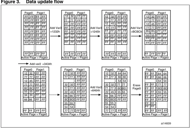
The following example shows the software management of three EEPROM variables (Var1, Var2 and Var3) with the following virtual addresses:
Var1: 5555h, Var2: 6666h and Var3: 7777h
Figure 3. Data update flow
2.1.2 EEPROM
software
description
This section describes the driver implemented for EEPROM emulation using the STM32F10xxx Flash memory driver provided by STMicroelectronics.
A sample demonstration program is also supplied to demonstrate and test the EEPROM emulation driver using the three variables Var1, Var2 and Var3 defined in the VirtAddVarTab table declared in the software main.c file.
Variable data (16 bits)
ai14608b
Variable virtual address (16 bits)
EEPROM variable element = 32-bit word
256 elements (1 Kbyte page) for Medium-density devices or
512 elements (2 Kbyte page) for High-density and Connectivity line devices
page0 page1 12 32 77 77 12 45 77 77 BC BC 55 55 FF FF FF FF FF FF FF FF FF FF FF FF FF FF FF FF FF FF FF FF 34 34 66 66 12 32 77 77 FF FF FF FF FF FF FF FF FF FF FF FF FF FF FF FF FF FF FF FF FF FF FF FF FF FF FF FF FF FF FF FF 12 32 77 77 12 45 77 77 BC BC 55 55 FF FF FF FF FF FF FF FF FF FF FF FF FF FF FF FF FF FF FF FF FF FF FF FF FF FF FF FF FF FF FF FF FF FF FF FF FF FF FF FF FF FF FF FF FF FF FF FF FF FF FF FF Page0 Page1
Active Page = Page0 FF FF FF FF FF FF FF FF 32 32 77 77 22 45 66 66 BD BD 55 55 FF FF FF FF FF FF FF FF FF FF FF FF FF FF FF FF FF FF 54 54 77 77 12 32 77 77 Add Var3 =1232h Add Var3 =1245h Add Var1 =BCBCh Add Var2 =6464h Erase Page0 Add var2 =3434h
Page0 Page1
Active Page = Page0
Page0 Page1
Active Page = Page0 12 32 77 77 12 45 77 77 FF FF FF FF FF FF FF FF FF FF FF FF FF FF FF FF FF FF FF FF FF FF FF FF FF FF FF FF Page0 Page1
Active Page = Page0
Page0 Page1
Active Page = Page0
Page0 Page1
Active Page = Page0
Page0 Page1
Active Page = Page1 32 32 77 77 22 45 66 66 BD BD 55 55 64 64 66 66 54 54 77 77 BD BD 55 55 FF FF FF FF FF FF 54 54 77 77 12 32 77 77 Page0 Page1
Active Page = Page1 FF FF FF FF FF FF FF FF FF FF FF FF 64 64 66 66 54 54 77 77 BD BD 55 55 FF FF FF FF FF FF FF FF FF FF FF FF FF FF ai14609
AN2594 Implementing EEPROM emulation
The project contains three source files in addition to the Flash memory library source files:
● eeprom.c: it contains C code for the following project routines:
EE_Init() EE_Format()
EE_FindValidPage()
EE_VerifyPageFullWriteVariable() EE_ReadVariable()
EE_PageTransfer() EE_WriteVariable()
● eeprom.h: it contains the routine prototypes and some declarations.
● main.c: this application program is an example using the described routines in order to write to and read from the EEPROM.
User API definition
The set of functions contained in the eeprom.c file, that are used for EEPROM emulation, are described below:
● EE_Init()
Sector header corruption is possible in the event of power loss during data update or sector erase / transfer. In this case, the EE_Init() function will attempt to restore the database to a known good state. This function should be called prior to accessing the database after each power-down. It accepts no parameters. The process is described in Table 2.
● EE_Format()
This function erases page0 and page1 and writes a VALID_PAGE header to page0.
● EE_FindValidPage()
This function reads both page headers and returns the valid page number. The passed parameter indicates if the valid page is sought for a write or read operation
(READ_FROM_VALID_PAGE or WRITE_IN_VALID_PAGE).
● EE_VerifyPageFullWriteVariable()
It implements the write process that must either update or create the first instance of a variable. It consists in finding the first empty location on the active page, starting from the end, and filling it with the passed virtual address and data of the variable. In the case the active page is full, the PAGE_FULL value is returned. This routine uses the parameters below:
– Virtual address: may be any of the three declared variables’ virtual addresses (Var1, Var2 or Var3)
– Data: the value of the variable to be stored
This function returns FLASH_COMPLETE on success, PAGE_FULL if there is not enough memory for a variable update, or a Flash memory error code to indicate operation failure (erase or program).
● EE_ReadVariable()
This function returns the data corresponding to the virtual address passed as a parameter. Only the last update is read. The function enters in a loop in which it reads the variable entries until the last one. If no occurrence of the variable is found, the ReadStatus variable is returned with the value “1”, otherwise it is reset to indicate that
Implementing EEPROM emulation AN2594
the variable has been found and the variable value is returned on the Read_data variable.
● EE_PageTransfer()
It transfers the most recent data (last variable updates) from a full page to an empty one. At the beginning, it determines the active page, which is the page the data is to be transferred from. The new page header field is defined and written (new page status is RECEIVE_DATA given that it is in the process of receiving data). When the data transfer is complete, the new page header is VALID_PAGE, the old page is erased and its header becomes ERASED.
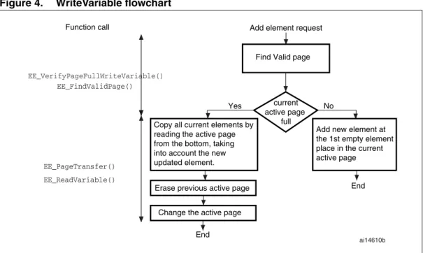
● EE_WriteVariable(..)
This function is called by the user application to update a variable. It uses the
EE_VerifyPageFullWriteVariable(), and EE_PageTransfer() routines that have already been described.
Figure 4 shows the procedure for updating a variable entry in the EEPROM.
Figure 4. WriteVariable flowchart
Key features
● User-configured emulated EEPROM size
● Increased Flash memory endurance: page erased only when it is full
● Non-volatile data variables can be updated infrequently
● Interrupt servicing during program/erase is possible
Add element request
current active page
full
Add new element at the 1st empty element place in the current active page
Erase previous active page
End
End
Change the active page
Find Valid page
Yes No
EE_FindValidPage()
Copy all current elements by reading the active page from the bottom, taking into account the new updated element.
EE_PageTransfer() EE_ReadVariable()
Function call
ai14610b
AN2594 Embedded application aspects
3
Embedded application aspects
This section gives some advice on how to overcome software limitations in embedded applications and to fulfill the needs of different applications.
3.1
Data granularity management
Emulated EEPROM can be used in embedded applications where non-volatile storage of data updated with a byte, half-word or word granularity is required. It generally depends on the user requirements and Flash memory architecture, such as stored data length, write access, etc.
The STM32F10xxx on-chip Flash memory allows 16-bit, half-word programming. Data can however be programmed by bytes or words by using some software techniques.
3.1.1
Programming on a word-by-word basis
The Flash memory driver provides a function that will write 32 bits of data “VarData” to the desired Flash memory address “VarAddress”: FLASH_ProgramWord(VarAddress, VarData). With this function, a whole word can be written to a specific embedded Flash memory location.
3.1.2
Programming on a byte-by-byte basis
Writing by bytes offers the user the possibility of storing more data variables. The performance may however be reduced.
Using the FLASH_ProgramHalfWord() function, both virtual address and data can be written in one go as a half word.
3.2
Wear leveling: Flash memory endurance improvement
In the STM32F10xxx on-chip Flash memory, each page can be programmed or erased reliably around 10 000 times.
For write-intensive applications that use more than two pages (3 or 4) for the emulated EEPROM, it is recommended to implement a wear-leveling algorithm to monitor and distribute the number of write cycles among the pages.
When no wear-leveling algorithm is used, the pages are not used at the same rate. Pages with long-lived data do not endure as many write cycles as pages that contain frequently updated data. The wear-leveling algorithm ensures that equal use is made of all the available write cycles for each sector.
3.2.1 Wear-leveling
implementation
example
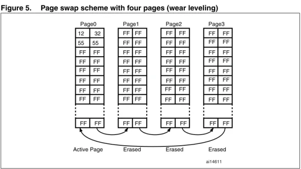
In this example, in order to enhance the emulated EEPROM capacity, four pages will be used (Page0, Page1, Page2 and Page3).
The wear-leveling algorithm is implemented as follows: when page n is full, the device switches to page n+1. Page n is garbage-collected and then erased. When it is the turn of
Embedded application aspects AN2594
Page3 to be full, the device goes back to Page0, Page3 is garbage-collected then erased and so on (refer to Figure 5).
Figure 5. Page swap scheme with four pages (wear leveling)
In the software, the wear-leveling algorithm can be implemented using the
EE_FindValidPage() function.
3.3
Page header recovery in case of power loss
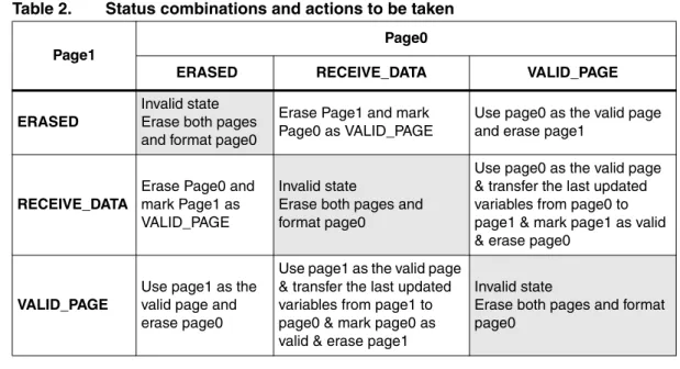
Data or page header corruption is possible in case of a power loss during a variable update, page erase or transfer.
To detect this corruption and recover from it, the EE_Init() routine is implemented. It should be called immediately after power-up. The principle of the routine is described in this application note. The routine uses the page status to check for integrity and perform repair if necessary.
After power loss, the EE_Init() routine is used to check the page header status. There are 9 possible status combinations, three of which are invalid. Table 2 shows the actions that should be taken based on the page statuses upon power-up.
12 32 55 55
FF FF FF FF FF FF
FF FF
FF FF
Active Page FF FF FF FF
FF FF FF FF FF FF FF FF FF FF FF FF
FF FF FF FF FF FF
FF FF FF FF FF FF FF FF FF FF
FF FF
FF FF FF FF
FF FF
FF FF FF FF
FF FF FF FF
FF FF FF FF
FF FF FF FF
FF FF
Erased Erased Erased
Page0 Page1 Page2 Page3
AN2594 Embedded application aspects
3.4 Cycling
capability
A program/erase cycle consists of one or more write accesses and one page erase operation.
When the EEPROM technology is used, each byte can be programmed and erased a finite number of times, typically in the range of 10 000 to 100 000.
However, in embedded Flash memory, the minimum erase size is the page and the number of program/erase cycles applied to a page is the number of possible erase cycles. The STM32F10xxx’s electrical characteristics guarantee 10 000 program/erase cycles per page. The maximum lifetime of the emulated EEPROM is thereby limited by the update rate of the most frequently written parameter.
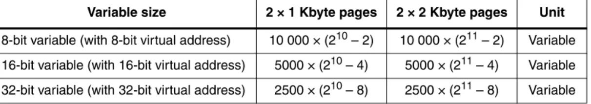
The cycling capability is dependent of the amount/size of data that the user wants to handle. In this example, two pages (of 1 Kbyte for Medium-density devices or 2 Kbyte for High-density and Connectivity line devices) are used and programmed with 16-bit data. To each variable corresponds a 16-bit virtual address. That is, each variable occupies a word of storage space. A page can store 1 Kbyte (for Medium-density devices) or 2 Kbyte (for High-density and Connectivity line devices) multiplied by the Flash memory endurance of 10 000 cycles gives a total of 10 000 Kbytes (for Medium-density devices) or 20 000 Kbytes (for High-density and Connectivity line devices) of data storage capacity for the lifetime of one page in the emulated Flash memory. Consequently, 20 000 Kbytes (for Medium-density devices) or 40 000 Kbytes (for High-density and Connectivity line devices) can be stored in the emulated EEPROM provided that two pages are used in the emulation process. If more than two pages are used, this number is multiplied accordingly.
Knowing the data width of a stored variable, it is possible to calculate the total number of variables that can be stored in the emulated EEPROM area during its lifetime.
Table 3 gives an idea of the number of variables that can be stored in the emulated EEPROM according to the variable virtual address and data sizes.
Table 2. Status combinations and actions to be taken
Page1
Page0
ERASED RECEIVE_DATA VALID_PAGE
ERASED
Invalid state Erase both pages and format page0
Erase Page1 and mark Page0 as VALID_PAGE
Use page0 as the valid page and erase page1
RECEIVE_DATA
Erase Page0 and mark Page1 as VALID_PAGE
Invalid state
Erase both pages and format page0
Use page0 as the valid page & transfer the last updated variables from page0 to page1 & mark page1 as valid & erase page0
VALID_PAGE
Use page1 as the valid page and erase page0
Use page1 as the valid page & transfer the last updated variables from page1 to page0 & mark page0 as valid & erase page1
Invalid state
Erase both pages and format page0
Embedded application aspects AN2594
Table 3. Maximum number of variables stored in emulated EEPROM (with 10 000 cycles)(1)(2)
1. These maximum numbers of variables do not include their corresponding virtual address. 2. The value subtracted from the maximum number of variables that can be written using two pages,
corresponds to the page status located at the top of the page. Depending on the variable granularity and, to preserve the alignment, some empty bytes are added to the page status. These bytes are also subtracted from this maximum number.
Variable size 2 × 1 Kbyte pages 2 × 2 Kbyte pages Unit
8-bit variable (with 8-bit virtual address) 10 000 × (210 – 2) 10 000 × (211 – 2) Variable 16-bit variable (with 16-bit virtual address) 5000 × (210 – 4) 5000 × (211 – 4) Variable 32-bit variable (with 32-bit virtual address) 2500 × (210 – 8) 2500 × (211 – 8) Variable
AN2594 Revision history
4 Revision
history
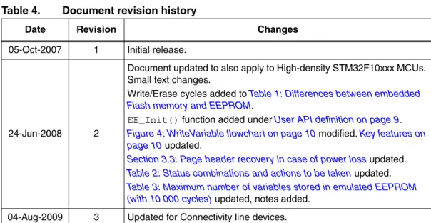
Table 4. Document revision history
Date Revision Changes
05-Oct-2007 1 Initial release.
24-Jun-2008 2
Document updated to also apply to High-density STM32F10xxx MCUs. Small text changes.
Write/Erase cycles added to Table 1: Differences between embedded Flash memory and EEPROM.
EE_Init() function added under User API definition on page 9. Figure 4: WriteVariable flowchart on page 10 modified. Key features on page 10 updated.
Section 3.3: Page header recovery in case of power loss updated. Table 2: Status combinations and actions to be taken updated. Table 3: Maximum number of variables stored in emulated EEPROM (with 10 000 cycles) updated, notes added.
AN2594
Please Read Carefully:
Information in this document is provided solely in connection with ST products. STMicroelectronics NV and its subsidiaries (“ST”) reserve the right to make changes, corrections, modifications or improvements, to this document, and the products and services described herein at any time, without notice.
All ST products are sold pursuant to ST’s terms and conditions of sale.
Purchasers are solely responsible for the choice, selection and use of the ST products and services described herein, and ST assumes no liability whatsoever relating to the choice, selection or use of the ST products and services described herein.
No license, express or implied, by estoppel or otherwise, to any intellectual property rights is granted under this document. If any part of this document refers to any third party products or services it shall not be deemed a license grant by ST for the use of such third party products or services, or any intellectual property contained therein or considered as a warranty covering the use in any manner whatsoever of such third party products or services or any intellectual property contained therein.
UNLESS OTHERWISE SET FORTH IN ST’S TERMS AND CONDITIONS OF SALE ST DISCLAIMS ANY EXPRESS OR IMPLIED WARRANTY WITH RESPECT TO THE USE AND/OR SALE OF ST PRODUCTS INCLUDING WITHOUT LIMITATION IMPLIED WARRANTIES OF MERCHANTABILITY, FITNESS FOR A PARTICULAR PURPOSE (AND THEIR EQUIVALENTS UNDER THE LAWS OF ANY JURISDICTION), OR INFRINGEMENT OF ANY PATENT, COPYRIGHT OR OTHER INTELLECTUAL PROPERTY RIGHT. UNLESS EXPRESSLY APPROVED IN WRITING BY AN AUTHORIZED ST REPRESENTATIVE, ST PRODUCTS ARE NOT RECOMMENDED, AUTHORIZED OR WARRANTED FOR USE IN MILITARY, AIR CRAFT, SPACE, LIFE SAVING, OR LIFE SUSTAINING APPLICATIONS, NOR IN PRODUCTS OR SYSTEMS WHERE FAILURE OR MALFUNCTION MAY RESULT IN PERSONAL INJURY, DEATH, OR SEVERE PROPERTY OR ENVIRONMENTAL DAMAGE. ST PRODUCTS WHICH ARE NOT SPECIFIED AS "AUTOMOTIVE GRADE" MAY ONLY BE USED IN AUTOMOTIVE APPLICATIONS AT USER’S OWN RISK.
Resale of ST products with provisions different from the statements and/or technical features set forth in this document shall immediately void any warranty granted by ST for the ST product or service described herein and shall not create or extend in any manner whatsoever, any liability of ST.
ST and the ST logo are trademarks or registered trademarks of ST in various countries. Information in this document supersedes and replaces all information previously supplied.
The ST logo is a registered trademark of STMicroelectronics. All other names are the property of their respective owners.
© 2009 STMicroelectronics - All rights reserved
STMicroelectronics group of companies
Australia - Belgium - Brazil - Canada - China - Czech Republic - Finland - France - Germany - Hong Kong - India - Israel - Italy - Japan - Malaysia - Malta - Morocco - Philippines - Singapore - Spain - Sweden - Switzerland - United Kingdom - United States of America