1.
1.
SECTIONS OF SOLIDS.
SECTIONS OF SOLIDS.
2.
2.
DEVELOPMENT.
DEVELOPMENT.
3.
3.
ISOMETRIC PROJECTION.
ISOMETRIC PROJECTION.
ENGINEERING APPLICATIONS
ENGINEERING APPLICATIONS
OF
OF
THE PRINCIPLES
THE PRINCIPLES
OF
OF
PROJECTIONS OF SOLIDES.
PROJECTIONS OF SOLIDES.
STUDY CAREFULLY
STUDY CAREFULLY
THE ILLUSTRATIONS GIVEN ON
THE ILLUSTRATIONS GIVEN ON
NEXT
SECTIONING A SOLID.
SECTIONING A SOLID.
An object ( here a solid ) is cut by
An object ( here a solid ) is cut by
some imaginary cutting plane
some imaginary cutting plane
to understand internal details of that object.
to understand internal details of that object.
The action of cutting is called
The action of cutting is called SECTIONINGSECTIONING a solid a solid
&
&
The plane of cutting is called
The plane of cutting is called SECTION PLANE.SECTION PLANE. Two cutting actions means section planes are recommended
Two cutting actions means section planes are recommended..
A) Section Plane perpendicular to Vp and inclined to Hp.
A) Section Plane perpendicular to Vp and inclined to Hp.
( This is a definition of an Aux. Inclined Plane i.e. A.I.P.)( This is a definition of an Aux. Inclined Plane i.e. A.I.P.)
NOTE:- This section plane appears NOTE:- This section plane appears
as a straight line in FV.as a straight line in FV.
B) Section Plane perpendicular to Hp and inclined to Vp.
B) Section Plane perpendicular to Hp and inclined to Vp.
( This is a definition of an Aux. Vertical Plane i.e. A.V.P.)( This is a definition of an Aux. Vertical Plane i.e. A.V.P.)
NOTE:- This section plane appears NOTE:- This section plane appears
as a straight line in TV.as a straight line in TV.
Remember:-1. After launching a section plane 1. After launching a section plane
either in FV or TV, the part towards observereither in FV or TV, the part towards observer
is assumed to be removed.is assumed to be removed.
2. As far as possible the smaller part is 2. As far as possible the smaller part is
assumed to be removed. assumed to be removed.
OBSERVER OBSERVER ASSUME ASSUME UPPER PART UPPER PART REMOVED
REMOVED SECT
ON PL ANE
SECT ON PL
ANE
IN FV .
IN FV . OBSERVER OBSERVER ASSUME ASSUME LOWER PART LOWER PART REMOVED REMOVED SECT
ON PLAN E
SECTON P LANE
IN TV.
IN TV.
(A)
(A)
(B)
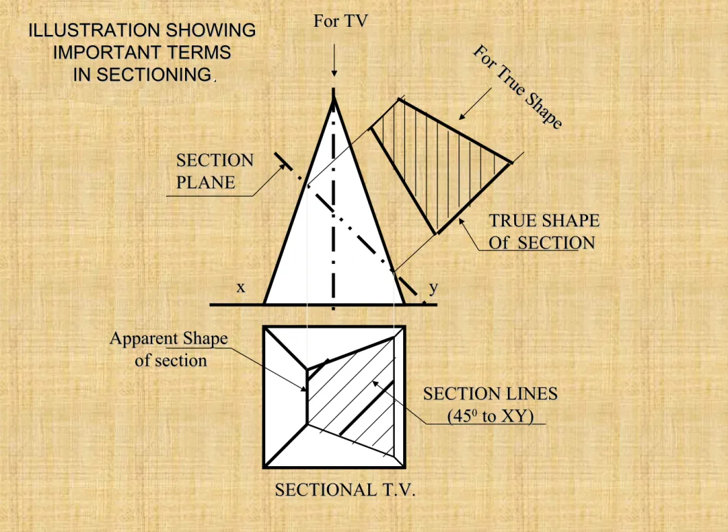
ILLUSTRATION SHOWING
ILLUSTRATION SHOWING
IMPORTANT TERMS
IMPORTANT TERMS
IN SECTIONING
IN SECTIONING..
x
x yy
TRUE SHAPE
TRUE SHAPE
Of SECTION
Of SECTION
SECTION
SECTION
PLANE
PLANE
SECTION LINES
SECTION LINES
(45
(4500 to XY) to XY) Apparent Shape
Apparent Shape
of section
of section
SECTIONAL T.V.
SECTIONAL T.V.
For TV
For TV
For
True S hape
For
Section Plane
Section Plane
Through Apex
Through Apex
Section Plane
Section Plane
Through Generators
Through Generators
Section Plane Parallel
Section Plane Parallel
to end generator.
to end generator.
Section Plane
Section Plane
Parallel to Axis.
Parallel to Axis.
Triangle
Triangle EllipseEllipse
Par abol
a
Par abol
a
Hyperbola
Hyperbola
Ellipse
Ellipse
Cylinder through
Cylinder through
generators.
generators.
Sq. Pyramid through
Sq. Pyramid through
all slant edges
all slant edges
Trapezium
Trapezium
Typical Section Planes
Typical Section Planes
&
&
Typical Shapes
Typical Shapes
Of
Of
Sections.
DEVELOPMENT OF SURFACES OF SOLIDS. DEVELOPMENT OF SURFACES OF SOLIDS.
MEANING:-ASSUME OBJECT HOLLOW AND MADE-UP OF THIN SHEET. CUT OPEN IT FROM ONE SIDE AND
ASSUME OBJECT HOLLOW AND MADE-UP OF THIN SHEET. CUT OPEN IT FROM ONE SIDE AND
UNFOLD THE SHEET COMPLETELY. THEN THE
UNFOLD THE SHEET COMPLETELY. THEN THE SHAPE OF THAT UNFOLDED SHEET IS CALLEDSHAPE OF THAT UNFOLDED SHEET IS CALLED
DEVELOPMENT OF LATERLAL SUEFACES
DEVELOPMENT OF LATERLAL SUEFACES OF THAT OBJECT OR SOLID. OF THAT OBJECT OR SOLID.
LATERLAL SURFACE
LATERLAL SURFACE IS THE SURFACE EXCLUDING SOLID’S TOP & BASE. IS THE SURFACE EXCLUDING SOLID’S TOP & BASE.
ENGINEERING APLICATION
ENGINEERING APLICATION::
THERE ARE SO MANY PRODUCTS OR OBJECTS WHICH ARE DIFFICULT TO MANUFACTURE BY
THERE ARE SO MANY PRODUCTS OR OBJECTS WHICH ARE DIFFICULT TO MANUFACTURE BY
CONVENTIONAL MANUFACTURING PROCESSES, BECAUSE OF THEIR SHAPES AND SIZES.
CONVENTIONAL MANUFACTURING PROCESSES, BECAUSE OF THEIR SHAPES AND SIZES.
THOSE ARE FABRICATED IN SHEET METAL INDUSTRY BY USING
THOSE ARE FABRICATED IN SHEET METAL INDUSTRY BY USING
DEVELOPMENT TECHNIQUE. THERE IS A VAST RANGE OF SUCH OBJECTS.
DEVELOPMENT TECHNIQUE. THERE IS A VAST RANGE OF SUCH OBJECTS.
EXAMPLES:-Boiler Shells & chimneys, Pressure Vessels, Shovels, Trays, Boxes & Cartons, Feeding Hoppers,
Boiler Shells & chimneys, Pressure Vessels, Shovels, Trays, Boxes & Cartons, Feeding Hoppers,
Large Pipe sections, Body & Parts of automotives, Ships, Aeroplanes and many more.
Large Pipe sections, Body & Parts of automotives, Ships, Aeroplanes and many more.
WHAT IS
WHAT IS
OUR OBJECTIVE
OUR OBJECTIVE
IN THIS TOPIC ?
IN THIS TOPIC ?
To learn methods of development of surfaces of
To learn methods of development of surfaces of
different solids, their sections and frustums
different solids, their sections and frustums..
1. Development is different drawing than PROJECTIONS.
1. Development is different drawing than PROJECTIONS.
2. It is a shape showing AREA, means it’s a 2-D plain drawing.
2. It is a shape showing AREA, means it’s a 2-D plain drawing.
3. Hence all dimensions of it must be TRUE dimensions.
3. Hence all dimensions of it must be TRUE dimensions.
4. As it is representing shape of an un-folded sheet, no edges can remain hidden
4. As it is representing shape of an un-folded sheet, no edges can remain hidden
And hence DOTTED LINES are never shown on development.And hence DOTTED LINES are never shown on development. But before going ahead,
But before going ahead,
note following
note following
Important points
Important points..
Study illustrations given on next page carefully.
D
H
D
S S
H
L
=
RL+ 3600R=Base circle radius.
L=Slant height. L= Slant edge.S = Edge of base
L
S
S
H= Height S = Edge of base H= Height D= base diameter
Development of lateral surfaces of different solids. (Lateral surface is the surface excluding top & base)
Prisms: No.of Rectangles
Cylinder: A Rectangle
Cone: (Sector of circle) Pyramids: (No.of
triangles)
Tetrahedron: Four Equilateral Triangles
All sides equal in length
L L
=
RL+ 3600R= Base circle radius of cone L= Slant height of cone
L1 = Slant height of cut part.
Base side
Top side
L
1 L1
L= Slant edge of pyramid L1 = Slant edge of cut part. DEVELOPMENT OF
FRUSTUM OF CONE
DEVELOPMENT OF
FRUSTUM OF SQUARE PYRAMID
STUDY NEXT
STUDY NEXT NINE
NINE
PROBLEMS OF
PROBLEMS OF
SECTIONS & DEVELOPMENT
SECTIONS & DEVELOPMENT
FRUSTUMS
X Y X1
Y1
a’
b’ e’
c ’ d’ A B C E D a e d b c TRUE SHAP E
A B C D E A
DEVELOPMENT a” b” c” d” e” Solution Steps:
Solution Steps:for sectional views:for sectional views:
Draw three views of standing prism.
Draw three views of standing prism.
Locate sec.plane in Fv as described.
Locate sec.plane in Fv as described.
Project points where edges are getting
Project points where edges are getting
Cut on Tv & Sv as shown in illustration.
Cut on Tv & Sv as shown in illustration.
Join those points in sequence and show
Join those points in sequence and show
Section lines in it.
Section lines in it.
Make remaining part of solid dark.
Make remaining part of solid dark.
For True Shape:
For True Shape:
Draw x
Draw x11yy11 // to sec. plane // to sec. plane Draw projectors on it from
Draw projectors on it from
cut points.
cut points.
Mark distances of points
Mark distances of points
of Sectioned part from Tv,
of Sectioned part from Tv,
on above projectors from
on above projectors from
x
x11yy11 and join in sequence. and join in sequence. Draw section lines in it.
Draw section lines in it.
It is required true shape.
It is required true shape.
For Development:
For Development:
Draw development of entire solid. Name from
Draw development of entire solid. Name from
cut-open edge I.e. A. in sequence as shown.
cut-open edge I.e. A. in sequence as shown.
Mark the cut points on respective edges.
Mark the cut points on respective edges.
Join them in sequence in st. lines.
Join them in sequence in st. lines.
Make existing parts dev.dark.
Make existing parts dev.dark.
Problem 1: A pentagonal prism , 30 mm base side & 50 mm axis
Problem 1: A pentagonal prism , 30 mm base side & 50 mm axis
is standing on Hp on it’s base whose one side is perpendicular to Vp.
is standing on Hp on it’s base whose one side is perpendicular to Vp.
It is cut by a section plane 45
It is cut by a section plane 450 0 inclined to Hp, through mid point of axis.inclined to Hp, through mid point of axis.
Draw Fv, sec.Tv & sec. Side view. Also draw true shape of section and
Draw Fv, sec.Tv & sec. Side view. Also draw true shape of section and
Development of surface of remaining solid.
Y h a b c d e g f X a’ h’b’ c’ g’ f’d’
e’
o’
X1
Y1
g” h”f” a”e” b”d” c”
A B C D E F A G H SECTIONAL T.V SECTIONAL S.V TRUE SHA
PE O F SEC
TION DEVELOPMENT SECT ION PLA NE Problem 2:
Problem 2: A cone, 50 mm base diameter and 70 mm axis is A cone, 50 mm base diameter and 70 mm axis is standing on it’s base on Hp. It cut by a section plane 45
standing on it’s base on Hp. It cut by a section plane 4500 inclined inclined
to Hp through base end of end generator.Draw projections,
to Hp through base end of end generator.Draw projections,
sectional views, true shape of section and development of surfaces
sectional views, true shape of section and development of surfaces
of remaining solid.
of remaining solid.
Solution Steps:
Solution Steps:for sectional views:for sectional views:
Draw three views of standing cone.
Draw three views of standing cone.
Locate sec.plane in Fv as described.
Locate sec.plane in Fv as described.
Project points where generators are
Project points where generators are
getting Cut on Tv & Sv as shown in
getting Cut on Tv & Sv as shown in
illustration.Join those points in
illustration.Join those points in
sequence and show Section lines in it.
sequence and show Section lines in it.
Make remaining part of solid dark.
Make remaining part of solid dark.
For True Shape:
For True Shape:
Draw x
Draw x11yy11 // to sec. plane // to sec. plane Draw projectors on it from
Draw projectors on it from
cut points.
cut points.
Mark distances of points
Mark distances of points
of Sectioned part from Tv,
of Sectioned part from Tv,
on above projectors from
on above projectors from
x
x11yy11 and join in sequence. and join in sequence.
Draw section lines in it.
Draw section lines in it.
It is required true shape.
It is required true shape.
For Development:
For Development:
Draw development of entire solid.
Draw development of entire solid.
Name from cut-open edge i.e. A.
Name from cut-open edge i.e. A.
in sequence as shown.Mark the cut
in sequence as shown.Mark the cut
points on respective edges.
points on respective edges.
Join them in sequence in
Join them in sequence in
curvature. Make existing parts
curvature. Make existing parts
dev.dark.
X a’ h’b’ c’ g’ f’d’ e’ Y
a’ h’b ’
e’ c’g ’
d’f ’
o’
o’
Problem 3: A cone 40mm diameter and 50 mm axis is resting on one generator on Hp( lying on Hp) which is // to Vp.. Draw it’s projections.It is cut by a horizontal section plane through it’s base center. Draw
sectional TV, development of the surface of the remaining part of cone.
A
B
C
D
E
F
A
G
H O
a1 h1 g1
f1
e1
d1
c1 b1
o1
SECTIONAL T.V
DEVELOPMENT
(SHOWING TRUE SHAPE OF SECTION) HORIZONTAL SECTION PLANE
h
a
b
c
d e g
f
O
Follow similar solution steps for Sec.views - True shape – Development as per previous problem!
A.V.P300 inclined to Vp
Through mid-point of axis.
X Y
1,2 3,8 4 ,7 5,6 1 2 3 4 5 6 7 8 2 1 8 7 6 5 4 3 b’ f’
a’ c’ d’ e’
a b c d e f b’ f’ a’ e’ c’ d’ a1 d1 b1 e1 c1 f1 X1 Y1
AS SECTION PLANE IS IN T.V.,
CUT OPEN FROM BOUNDRY EDGE C1 FOR DEVELOPMENT.
TRU E SH
APE OF S
ECTION
C D E F A B C
DEVELOPMENT SECTIONAL F.V.
Problem 4:
Problem 4: A hexagonal prism. 30 mm base side & A hexagonal prism. 30 mm base side & 55 mm axis is lying on Hp on it’s rect.face with axis
55 mm axis is lying on Hp on it’s rect.face with axis
// to Vp. It is cut by a section plane normal to Hp and
// to Vp. It is cut by a section plane normal to Hp and
30
3000 inclined to Vp bisecting axis. inclined to Vp bisecting axis.
Draw sec. Views, true shape & development.
Draw sec. Views, true shape & development.
Use similar steps for sec.views & true shape. Use similar steps for sec.views & true shape.
NOTE:
NOTE: for development, always cut open object from for development, always cut open object from From an edge in the boundary of the view in which
From an edge in the boundary of the view in which
sec.plane appears as a line.
sec.plane appears as a line.
Here it is Tv and in boundary, there is c1 edge.Hence
Here it is Tv and in boundary, there is c1 edge.Hence
it is opened from c and named C,D,E,F,A,B,C.
it is opened from c and named C,D,E,F,A,B,C.
Note
Note the steps to locate the steps to locate
Points 1, 2 , 5, 6 in sec.Fv:
Points 1, 2 , 5, 6 in sec.Fv:
Those are transferred to
Those are transferred to
1
1stst TV, then to 1 TV, then to 1stst Fv and Fv and
Then on 2
1’ 2’ 3’ 4’ 5’ 6’ 7’ 7 1 5 4 3 2 6 7 1 6 5 4 3 2 a b c d e f g 4 4 5 3 6 2 7 1 A B C D E A F G O O’
d’e’ c’f’ g’b’ a’
X Y X1 Y1 TRUE SHAP E F.V. SECTIONAL TOP VIEW. DEV ELO PM EN T
Problem 5:A solid composed of a half-cone and half- hexagonal pyramid is shown in figure.It is cut by a section plane 450 inclined to Hp, passing through
mid-point of axis.Draw F.v., sectional T.v.,true shape of section and development of remaining part of the solid.
( take radius of cone and each side of hexagon 30mm long and axis 70mm.)
Note:
Note:
Fv & TV 8f two solids
Fv & TV 8f two solids
sandwiched
sandwiched
Section lines style in both:
Section lines style in both:
Development of
Development of
half cone & half pyramid:
o’ h a b c d g f o e
a’ h’b’ c’ g’ d’f’ e’
X Y
=
RL+ 3600R=Base circle radius. L=Slant height.
A B
C
D E F
G H A O 1 3 2 4 7 6 5 L 1 1 2 2 3 3 4 4 5 5 6 6 7 7 1’ 1’ 2’ 2’ 3’
3’5’5’ 4’4’ 6’
6’
7’
7’ Problem 6:
Problem 6: Draw a semicircle 0f 100 mm diameter and inscribe in it a largestDraw a semicircle 0f 100 mm diameter and inscribe in it a largest
circle.If the semicircle is development of a cone and inscribed circle is some
circle.If the semicircle is development of a cone and inscribed circle is some
curve on it, then draw the projections of cone showing that curve.
curve on it, then draw the projections of cone showing that curve.
Solution Steps:
Solution Steps:
Draw semicircle of given diameter, divide it in 8 Parts and inscribe in it
Draw semicircle of given diameter, divide it in 8 Parts and inscribe in it
a largest circle as shown.Name intersecting points 1, 2, 3 etc.
a largest circle as shown.Name intersecting points 1, 2, 3 etc.
Semicircle being dev.of a cone it’s radius is slant height of cone.( L )
Semicircle being dev.of a cone it’s radius is slant height of cone.( L )
Then using above formula find R of base of cone. Using this data
Then using above formula find R of base of cone. Using this data
draw Fv & Tv of cone and form 8 generators and name.
draw Fv & Tv of cone and form 8 generators and name.
Take o -1 distance from dev.,mark on TL i.e.o’a’ on Fv & bring on o’b’
Take o -1 distance from dev.,mark on TL i.e.o’a’ on Fv & bring on o’b’
and name 1’ Similarly locate all points on Fv. Then project all on Tv
and name 1’ Similarly locate all points on Fv. Then project all on Tv
on respective generators and join by smooth curve.
on respective generators and join by smooth curve.
L
L
TO DRAW PRINCIPAL
TO DRAW PRINCIPAL
VIEWS FROM GIVEN
VIEWS FROM GIVEN
DEVELOPMENT.
h a b c d g f e o’
a’ h’b’ c’ g’ f’d’ e’
X Y
A B
C
D E F
G H A O L 1 2 3 4
5 6
7
=
RL+ 3600R=Base circle radius. L=Slant height.
1’
1’
2’
2’ 3’3’
4’ 4’ 5’ 5’ 6’ 6’ 7’ 7’ 1
1 22
3 3 4 4 5 5 6 6 7 7
Problem 7:Draw a semicircle 0f 100 mm diameter and inscribe in it a largest
Problem 7:Draw a semicircle 0f 100 mm diameter and inscribe in it a largest
rhombus.If the semicircle is development of a cone and rhombus is some curve
rhombus.If the semicircle is development of a cone and rhombus is some curve
on it, then draw the projections of cone showing that curve.
on it, then draw the projections of cone showing that curve.
TO DRAW PRINCIPAL
TO DRAW PRINCIPAL
VIEWS FROM GIVEN
VIEWS FROM GIVEN
DEVELOPMENT.
DEVELOPMENT.
Solution Steps:
Solution Steps:
Similar to previous
Similar to previous
Problem:
X Y
e’ a’ h’b’ c’ g’ f’d’
o’ h a b c d e g f O DEVELOPMENT A B C D E F A G H O O 1 1 2 2 3 3 4 4 6
6 55
7 7 1’ 1’ 2’ 2’ 3’ 3’ 4’ 4’ 5’ 5’ 6’ 6’ 7’ 7’ 1 1 2 2 3 3 4 4 5 5 6 6 7 7 HELIX CURVE
HELIX CURVE
Problem 9:
Problem 9: A particle which is initially on base circle of a cone, standing A particle which is initially on base circle of a cone, standing
on Hp, moves upwards and reaches apex in one complete turn around the cone.
on Hp, moves upwards and reaches apex in one complete turn around the cone.
Draw it’s path on projections of cone as well as on it’s development.
Draw it’s path on projections of cone as well as on it’s development.
Take base circle diameter 50 mm and axis 70 mm long.
Take base circle diameter 50 mm and axis 70 mm long.
It’s a construction of curve
It’s a construction of curve
Helix of one turn on cone
Helix of one turn on cone::
Draw Fv & Tv & dev.as usual
Draw Fv & Tv & dev.as usual
On all form generators & name.
On all form generators & name. Construction of curve Helix::
Construction of curve Helix::
Show 8 generators on both views
Show 8 generators on both views
Divide axis also in same parts.
Divide axis also in same parts.
Draw horizontal lines from those
Draw horizontal lines from those
points on both end generators.
points on both end generators.
1’ is a point where first horizontal
1’ is a point where first horizontal
Line & gen. b’o’ intersect.
Line & gen. b’o’ intersect.
2’ is a point where second horiz.
2’ is a point where second horiz.
Line & gen. c’o’ intersect.
Line & gen. c’o’ intersect.
In this way locate all points on Fv.
In this way locate all points on Fv.
Project all on Tv.Join in curvature.
Project all on Tv.Join in curvature.
For Development:
For Development:
Then taking each points true Then taking each points true Distance From resp.generator Distance From resp.generator from apex, Mark on development from apex, Mark on development & join.
H
3-D DRAWINGS CAN BE DRAWN IN NUMEROUS WAYS AS SHOWN BELOW. ALL THESE DRAWINGS MAY BE CALLED
3-DIMENSIONAL DRAWINGS, OR PHOTOGRAPHIC OR PICTORIAL DRAWINGS. HERE NO SPECIFIC RELATION AMONG H, L & D AXES IS MENTAINED.
H
NOW OBSERVE BELOW GIVEN DRAWINGS. ONE CAN NOTE SPECIFIC INCLINATION
AMONG H, L & D AXES.
ISO MEANS SAME, SIMILAR OR EQUAL. HERE ONE CAN FIND
EDUAL INCLINATION AMONG H, L & D AXES. EACH IS 1200 INCLINED WITH OTHER TWO.
HENCE IT IS CALLED ISOMETRIC DRAWING
H
L
IT IS A TYPE OF PICTORIAL PROJECTION IN WHICH ALL THREE DIMENSIONS OF AN OBJECT ARE SHOWN IN ONE VIEW AND IF REQUIRED, THEIR ACTUAL SIZES CAN BE
MEASURED DIRECTLY FROM IT.
IN THIS 3-D DRAWING OF AN OBJECT, ALL THREE DIMENSIONAL AXES ARE MENTAINED AT EQUAL INCLINATIONS
WITH EACH OTHER.( 1200)
PURPOSE OF ISOMETRIC DRAWING IS TO UNDERSTAND
OVERALL SHAPE, SIZE & APPEARANCE OF AN OBJECT PRIOR TO IT’S PRODUCTION.
ISOMETRIC AXES, LINES AND PLANES:
The three lines AL, AD and AH, meeting at point A and making 1200 angles with each other are termed Isometric Axes.
The lines parallel to these axes are called Isometric Lines. The planes representing the faces of of the cube as well as
other planes parallel to these planes are called Isometric Planes.
ISOMETRIC SCALE:
When one holds the object in such a way that all three dimensions are visible then in the process all dimensions become proportionally inclined to observer’s eye sight and hence appear apparent in lengths. This reduction is 0.815 or 9 / 11 ( approx.) It forms a reducing scale which Is used to draw isometric drawings and is called Isometric scale.
In practice, while drawing isometric projection, it is necessary to convert true lengths into isometric lengths for measuring and marking the sizes. This is conveniently done by constructing an isometric scale as described on next page.
H
A
ISOMETRIC VIEW ISOMETRIC PROJECTION
H
H
TYPES OF ISOMETRIC DRAWINGS
Drawn by using Isometric scale ( Reduced dimensions ) Drawn by using True scale
( True dimensions )
450
300
0
1
2
3
4
0
1
2
3
4
TRUE LEN
GTHS
ISOM. LENG
THS
Isometric scale [ Line AC ] required for Isometric Projection
A B
C D
CONSTRUCTION OF ISOM.SCALE.
From point A, with line AB draw 300 and
450 inclined lines AC & AD resp on AD.
Mark divisions of true length and from each division-point draw vertical lines upto AC line.
SHAPE
Isometric view if the Shape is
F.V. or T.V.
TRIANGLE A B RECTANGLE D C H L D A B C D A B D C L H L D L 1 2 3 A
B 1 3
2 A B 3 1 2 A B H L D L 1 2 3 4 PENTAGON A B C D E 1 2 3 4 A B C D E 1 2 3 4 A B C D E ISOMETRIC OF PLANE FIGURES
AS THESE ALL ARE 2-D FIGURES
WE REQUIRE ONLY TWO ISOMETRIC AXES.
IF THE FIGURE IS FRONT VIEW, H & L AXES ARE REQUIRED.
IF THE FIGURE IS TOP VIEW, D & L AXES ARE REQUIRED.
Shapes containing Inclined lines should be
enclosed in a rectangle as shown.
Then first draw isom. of that rectangle and then inscribe that shape as it
1
4 2
3
A B
D C
1 4
2
3 A
B
D
C
Z
STUDY
ILLUSTRATIONS
DRAW ISOMETRIC VIEW OF A CIRCLE IF IT IS A TV OR FV.
FIRST ENCLOSE IT IN A SQUARE. IT’S ISOMETRIC IS A RHOMBUS WITH D & L AXES FOR TOP VIEW.
THEN USE H & L AXES FOR ISOMETRIC WHEN IT IS FRONT VIEW.
FOR CONSTRUCTION USE RHOMBUS METHOD SHOWN HERE. STUDY IT.
25 R
100 MM
50 MM
Z
STUDY
ILLUSTRATIONS
DRAW ISOMETRIC VIEW OF THE FIGURE SHOWN WITH DIMENTIONS (ON RIGHT SIDE) CONSIDERING IT FIRST AS F.V. AND THEN T.V.
IF TOP VIEW IF FRONT VIEW
CIRCLE HEXAGON
SEMI CIRCLE
ISOMETRIC OF
PLANE FIGURES
AS THESE ALL ARE 2-D FIGURES WE REQUIRE ONLY TWO ISOMETRIC AXES.
IF THE FIGURE IS FRONT VIEW, H & L AXES ARE REQUIRED.
IF THE FIGURE IS TOP VIEW, D & L AXES ARE
REQUIRED.
SHAPE
IF F.V.
IF T.V.
For Isometric of Circle/Semicircle use Rhombus method. Construct Rhombus
of sides equal to Diameter of circle always. ( Ref. topic ENGG. CURVES.)
For Isometric of Circle/Semicircle use Rhombus method. Construct it of sides equal to diameter of circle always.
( Ref. Previous two pages.)
D L
1
2
3 4
A
B
C D
E
D L
1
2
3 4
A
B
C D
E
ISOMETRIC VIEW OF PENTAGONAL PYRAMID
STANDING ON H.P. (Height is added from center of pentagon)
ISOMETRIC VIEW OF BASE OF PENTAGONAL PYRAMID
STANDING ON H.P.
Z
STUDY
ILLUSTRATIONS
H
L
1
2
3 4
A
B
C D E
Z
STUDY
ILLUSTRATIONS
ISOMETRIC VIEW OF
PENTAGONALL PRISM
LYING ON H.P.
ISOMETRIC VIEW OF
HEXAGONAL PRISM
STANDING ON H.P.
Z
STUDY
ILLUSTRATIONS
CYLINDER LYING ON H.P.
CYLINDER STANDING ON H.P.
Z
STUDY
ILLUSTRATIONS
HALF CYLINDER
LYING ON H.P.
( with flat face // to H.P.)
HALF CYLINDER
STANDING ON H.P.
( ON IT’S SEMICIRCULAR BASE)
Z
STUDY
ILLUSTRATIONS
ISOMETRIC VIEW OF A FRUSTOM OF SQUARE PYRAMID
STANDING ON H.P. ON IT’S LARGER BASE.
40 20 60
X Y
FV
TV
ISOMETRIC VIEW OF
FRUSTOM OF PENTAGONAL PYRAMID
40
20
60
STUDY
ILLUSTRATION
1
2 3
4 y
A
B
C
D E
40 20 60
x FV
TV
PROJECTIONS OF FRUSTOM OF PENTAGONAL PYRAMID ARE GIVEN.
DRAW IT’S ISOMETRIC VIEW.
SOLUTION STEPS:
FIRST DRAW ISOMETRIC OF IT’S BASE.
THEN DRAWSAME SHAPE AS TOP, 60 MM ABOVE THE BASE PENTAGON CENTER.
THEN REDUCE THE TOP TO 20 MM SIDES AND JOIN WITH THE PROPER BASE CORNERS.
Z
STUDY
ILLUSTRATIONS
ISOMETRIC VIEW OF A FRUSTOM OF CONE STANDING
ON H.P. ON IT’S LARGER BASE.
FV
TV
40 20 60
X Y
50
Z
STUDY
ILLUSTRATIONS
PROBLEM: A SQUARE PYRAMID OF 30 MM BASE SIDES AND 50 MM LONG AXIS, IS CENTRALLY PLACED ON THE TOP OF A
CUBE OF 50 MM LONG EDGES.DRAW ISOMETRIC VIEW OF THE PAIR.
50
30
a
b
c o
p p
a
b
c
o
Z
STUDY
ILLUSTRATIONS
PROBLEM: A TRIANGULAR PYRAMID OF 30 MM BASE SIDES AND 50 MM LONG AXIS, IS CENTRALLY PLACED ON THE TOP OF A CUBE OF 50 MM LONG EDGES.
DRAW ISOMETRIC VIEW OF THE PAIR.
SOLUTION HINTS.
TO DRAW ISOMETRIC OF A CUBE IS SIMPLE. DRAW IT AS USUAL.
BUT FOR PYRAMID AS IT’S BASE IS AN EQUILATERAL TRIANGLE, IT CAN NOT BE DRAWN DIRECTLY.SUPPORT OF IT’S TV IS REQUIRED.
SO DRAW TRIANGLE AS A TV, SEPARATELY AND NAME VARIOUS POINTS AS SHOWN.
AFTER THIS PLACE IT ON THE TOP OF CUBE AS SHOWN.
THEN ADD HEIGHT FROM IT’S CENTER AND COMPLETE IT’S ISOMETRIC AS SHOWN.
Z
STUDY
ILLUSTRATIONS
50
50
30 D 30 10 30
+
FV
TV
PROBLEM:
A SQUARE PLATE IS PIERCED THROUGH CENTRALLY
BY A CYLINDER WHICH COMES OUT EQUALLY FROM BOTH FACES OF PLATE. IT’S FV & TV ARE SHOWN. DRAW ISOMETRIC VIEW.
Z
STUDY
ILLUSTRATIONS
30 10 30
60 D
40 SQUARE
FV
TV
PROBLEM:
A CIRCULAR PLATE IS PIERCED THROUGH CENTRALLY
BY A SQUARE PYRAMID WHICH COMES OUT EQUALLY FROM BOTH FACES OF PLATE. IT’S FV & TV ARE SHOWN. DRAW ISOMETRIC VIEW.
Z
STUDY
ILLUSTRATIONS
X Y
30 D 50 D
10
40 20
40
FV
TV
F.V. & T.V. of an object are given. Draw it’s isometric view.
P r R R r P C
C = Center of Sphere. P = Point of contact
R = True Radius of Sphere r = Isometric Radius.
R r Iso-D irecti on P r R C r r
ISOMETRIC PROJECTIONS OF SPHERE & HEMISPHERE
r
R 450
300
TO DRAW ISOMETRIC PROJECTION OF A HEMISPHERE
TO DRAW ISOMETRIC PROJECTION OF A SPHERE
1. FIRST DRAW ISOMETRIC OF SQUARE PLATE. 2. LOCATE IT’S CENTER. NAME IT P.
3. FROM PDRAW VERTICAL LINE UPWARD, LENGTH ‘ r mm’ AND LOCATE CENTER OF SPHERE “C”
4. ‘C’ AS CENTER, WITH RADIUS ‘R’ DRAW CIRCLE. THIS IS ISOMETRIC PROJECTION OF A SPHERE.
Adopt same procedure. Draw lower semicircle only.
Then around ‘C’ construct Rhombus of Sides equal to
Isometric Diameter. For this use iso-scale. Then construct ellipse in
P r R
r
r 50 D
30 D
50 D 50
r
R 450
300 PROBLEM:
A HEMI-SPHERE IS CENTRALLY PLACED ON THE TOP OF A FRUSTOM OF CONE.
DRAW ISOMETRIC PROJECTIONS OF THE ASSEMBLY.
FIRST CONSTRUCT ISOMETRIC SCALE. USE THIS SCALE FOR ALL DIMENSIONS IN THIS PROBLEM.
Z
STUDY ILLUSTRATIONS
a
b c
d 1
2 3
4
o 1’
4’ 3’
2’
1
2 4
3
X Y
Z
STUDY
ILLUSTRATIONS
A SQUARE PYRAMID OF 40 MM BASE SIDES AND 60 MM AXIS IS CUT BY AN INCLINED SECTION PLANE THROUGH THE MID POINT OF AXIS AS SHOWN.DRAW ISOMETRIC VIEW OF SECTION OF PYRAMID.
Z
STUDY
ILLUSTRATIONS
X Y
50
20
25
25 20
O
O
F.V. & T.V. of an object are given. Draw it’s isometric view.
Z
STUDY
ILLUSTRATIONS
x y
FV
TV
35
35
10
30 20 10
40
70
O
O
F.V. & T.V. of an object are given. Draw it’s isometric view.
Z
STUDY
ILLUSTRATIONS
x y
FV
SV
TV
30
30 10
30 10 30
ALL VIEWS IDENTICAL
F.V. & T.V. and S.V.of an object are given. Draw it’s isometric view.
x y
FV SV
TV
Z
STUDY
ILLUSTRATIONS
10
40 60
60 40
ALL VIEWS IDENTICAL
F.V. & T.V. and S.V.of an object are given. Draw it’s isometric view.
x y
FV SV
TV
ALL VIEWS IDENTICAL
40 60
60 40
10
F.V. & T.V. and S.V.of an object are given. Draw it’s isometric view.
Z
STUDY
ILLUSTRATIONS
ORTHOGRAPHIC PROJECTIONS
FRONT VIEW
TOP VIEW
L.H.SIDE VIEW
x y
20
20
20
50
20 20 20 20
30
O
O
F.V. & T.V. and S.V.of an object are given. Draw it’s isometric view.
Z
STUDY
ILLUSTRATIONS
40 20
30 SQUARE
20 50
60 30 10
F.V.
S.V.
O
O
F.V. and S.V.of an object are given. Draw it’s isometric view.
Z
STUDY
ILLUSTRATIONS
40
10
50
80 10
30 D 45
FV
TV
O
O
F.V. & T.V. of an object are given. Draw it’s isometric view.
Z
STUDY
ILLUSTRATIONS
O
FV
TV
X O Y
40
10
25
25
30 R 10
100
10 30 10
20 D
F.V. & T.V. of an object are given. Draw it’s isometric view.
Z
STUDY
ILLUSTRATIONS
O
O
10
30
50
10 35
20 D
30 D 60 D
FV
TV
X Y
RECT. SLOT
F.V. & T.V. of an object are given. Draw it’s isometric view.
Z
STUDY
ILLUSTRATIONS
O
10
O
40
25 15
25
25
25
25 80
10
F.V. S.V.
F.V. and S.V.of an object are given. Draw it’s isometric view.
Z
STUDY
ILLUSTRATIONS
O
450
X
TV FV
Y
30 D 30
40
40
40 15
O
F.V. & T.V. of an object are given. Draw it’s isometric view.
Z
STUDY
ILLUSTRATIONS
O
O
20
20 15
30
60 30
20 20 40
100
50
HEX PART
F.V. and S.V.of an object are given. Draw it’s isometric view.
Z
STUDY
ILLUSTRATIONS
O
O
10
10
30
10
30 40
20
80 30 F.V.
T.V.
X Y
F.V. & T.V. of an object are given. Draw it’s isometric view.
Z
STUDY
ILLUSTRATIONS
FV LSV
X Y
10
O
FV LSV
X Y
10 10 15
25
25
10 50
O
F.V. and S.V.of an object are given. Draw it’s isometric view.
Z
STUDY
ILLUSTRATIONS
35
36 NOTE THE SMALL CHZNGE IN 2ND FV & SV.
Y X
F.V. LEFT S.V.
30 20 10 20
15
15
15 30
50
10
15
O O
F.V. and S.V.of an object are given. Draw it’s isometric view.
Z
STUDY
ILLUSTRATIONS
30
40
10
60
30
40
F.V. S.V.
O O
F.V. and S.V.of an object are given. Draw it’s isometric view.
Z
STUDY
ILLUSTRATIONS
PROJECTIONS OF STRAIGHT LINES
1. A line AB is in first quadrant. Its ends A and B are 25mm and 65mm in front of VP respectively. The distance between the end projectors is 75mm. The line is inclined at 300 to VP and its VT is 10mm above HP. Draw the projections of AB
and determine its true length and HT and inclination with HP.
2. A line AB measures 100mm. The projections through its VT and end A are 50mm apart. The point A is 35mm above HP and 25mm in front VP. The VT is 15mm above HP. Draw the projections of line and determine its HT and
Inclinations with HP and VP.
3. Draw the three views of line AB, 80mm long, when it is lying in profile plane and inclined at 350 to HP. Its end A is in HP and 20mm in front of VP, while other
end B is in first quadrant. Determine also its traces.
4. A line AB 75 mm long, has its one end A in VP and other end B 15mm above HP and 50mm in front of VP. Draw the projections of line when sum of
inclinations with HP and VP is 900. Determine the true angles of inclination and
show traces.
5. A line AB is 75mm long and lies in an auxiliary inclined plane (AIP) which makes an angle of 450 with the HP. The front view of the line measures 55mm.
The end A is in VP and 20mm above HP. Draw the projections of the line AB and find its inclination with HP and VP.
6. Line AB lies in an AVP 500 inclined to Vp while line is 300 inclined to Hp. End
A is 10 mm above Hp. & 15 mm in front of Vp.Distance between projectors is 50 mm.Draw projections and find TL and inclination of line with Vp. Locate traces also.
APPLICATIONS OF LINES
Room , compound wall cases
7) A room measures 8m x 5m x4m high. An electric point hang in the center of ceiling and 1m below it. A thin straight wire connects the point to the switch in one of the corners of the room and 2m above the floor. Draw the projections of the and its length and slope angle with the floor.
8) A room is of size 6m\5m\3.5m high. Determine graphically the real distance between the top corner and its diagonally apposite bottom corners. consider appropriate scale
9) Two pegs A and B are fixed in each of the two adjacent side walls of the rectangular room 3m x 4m sides. Peg A is 1.5m above the floor, 1.2m from the longer side wall and is protruding 0.3m from the wall. Peg B is 2m above the floor, 1m from other side wall and protruding 0.2m from the wall. Find the distance between the ends of the two pegs. Also find the height of the roof if the shortest distance between peg A and and center of the ceiling is 5m.
10) Two fan motors hang from the ceiling of a hall 12m x 5m x 8m high at heights of 4m and 6m respectively. Determine graphically the distance between the motors. Also find the distance of each motor from the top corner joining end and front wall.
POLES,ROADS, PIPE LINES,, NORTH- EAST-SOUTH WEST, SLOPE AND GRADIENT CASES.
12)Three vertical poles AB, CD and EF are lying along the corners of equilateral triangle lying on the ground of 100mm sides. Their lengths are 5m, 8m and 12m respectively. Draw their projections and find real distance between their top ends.
13) A straight road going up hill from a point A due east to another point B is 4km long and has a slop of 250. Another straight road from B due 300 east of north to a point C is also 4
kms long but going downward and has slope of 150. Find the length and slope of the straight
road connecting A and C.
14) An electric transmission line laid along an uphill from the hydroelectric power station due west to a substation is 2km long and has a slop of 300. Another line from the substation,
running W 450 N to village, is 4km long and laid on the ground level. Determine the length
and slope of the proposed telephone line joining the the power station and village.
15) Two wire ropes are attached to the top corner of a 15m high building. The other end of one wire rope is attached to the top of the vertical pole 5m high and the rope makes an angle of depression of 450. The rope makes 300 angle of depression and is attached to the top of a
2m high pole. The pole in the top view are 2m apart. Draw the projections of the wire ropes.
16) Two hill tops A and B are 90m and 60m above the ground level respectively. They are observed from the point C, 20m above the ground. From C angles and elevations for A and B are 450 and 300 respectively. From B angle of elevation of A is 450. Determine the two
PROJECTIONS OF
PLANES:-1. A thin regular pentagon of 30mm sides has one side // to Hp and 300 inclined to Vp while its surface is 450
inclines to Hp. Draw its projections.
2. A circle of 50mm diameter has end A of diameter AB in Hp and AB diameter 300 inclined to Hp. Draw its projections if
a) the TV of same diameter is 450 inclined to Vp, OR b) Diameter AB is in profile plane.
3. A thin triangle PQR has sides PQ = 60mm. QR = 80mm. and RP = 50mm. long respectively. Side PQ rest on ground and makes 300 with Vp. Point P is 30mm in front of Vp and R is 40mm above ground. Draw its
projections.
4. An isosceles triangle having base 60mm long and altitude 80mm long appears as an equilateral triangle of 60mm sides with one side 300 inclined to XY in top view. Draw its projections.
5. A 300-600 set-square of 40mm long shortest side in Hp appears is an isosceles triangle in its TV. Draw
projections of it and find its inclination with Hp.
6. A rhombus of 60mm and 40mm long diagonals is so placed on Hp that in TV it appears as a square of 40mm long diagonals. Draw its FV.
7. Draw projections of a circle 40 mm diameter resting on Hp on a point A on the circumference with its surface 300
inclined to Hp and 450 to Vp.
8. A top view of plane figure whose surface is perpendicular to Vp and 600 inclined to Hp is regular hexagon of 30mm
sides with one side 300 inclined to xy.Determine it’s true shape.
9. Draw a rectangular abcd of side 50mm and 30mm with longer 350 with XY, representing TV of a quadrilateral
plane ABCD. The point A and B are 25 and 50mm above Hp respectively. Draw a suitable Fv and determine its true shape.
10.Draw a pentagon abcde having side 500 to XY, with the side ab =30mm, bc = 60mm, cd =50mm, de = 25mm and
angles abc 1200, cde 1250. A figure is a TV of a plane whose ends A,B and E are 15, 25 and 35mm above Hp
PROJECTIONS OF SOLIDS
1. Draw the projections of a square prism of 25mm sides base and 50mm long axis. The prism is resting with one of its corners in VP and axis inclined at 300 to VP and parallel to
HP.
2. A pentagonal pyramid, base 40mm side and height 75mm rests on one edge on its base on the ground so that the highest point in the base is 25mm. above ground. Draw the
projections when the axis is parallel to Vp. Draw an another front view on an AVP inclined at 300 to edge on which it is resting so that the base is visible.
3. A square pyramid of side 30mm and axis 60 mm long has one of its slant edges
inclined at 450 to HP and a plane containing that slant edge and axis is inclined at 300 to
VP. Draw the projections.
4. A hexagonal prism, base 30mm sides and axis 75mm long, has an edge of the base parallel to the HP and inclined at 450 to the VP. Its axis makes an angle of 600 with the
HP. Draw its projections. Draw another top view on an auxiliary plane inclined at 500 to
the HP.
5. Draw the three views of a cone having base 50 mm diameter and axis 60mm long It is resting on a ground on a point of its base circle. The axis is inclined at 400 to ground and
at 300 to VP.
6. Draw the projections of a square prism resting on an edge of base on HP. The axis
makes an angle of 300 with VP and 450 with HP. Take edge of base 25mm and axis length
as 125mm.
7. A right pentagonal prism is suspended from one of its corners of base. Draw the
projections (three views) when the edge of base apposite to the point of suspension makes an angle of 300 to VP. Take base side 30mm and axis length 60mm.s
9. A cube of 40mm long edges is resting on the ground with its vertical faces equally
inclined to the VP. A right circular cone base 25mm diameter and height 50mm is placed centrally on the top of the cube so that their axis are in a straight line. Draw the front and top views of the solids. Project another top view on an AIP making 450 with
the HP
10.A square bar of 30mm base side and 100mm long is pushed through the center of a cylindrical block of 30mm thickness and 70mm diameter, so that the bar comes out equally through the block on either side. Draw the front view, top view and side view of the solid when the axis of the bar is inclined at 300 to HP and parallel to VP, the
sides of a bar being 450 to VP.
11.A cube of 50mm long edges is resting on the ground with its vertical faces equally inclined to VP. A hexagonal pyramid , base 25mm side and axis 50mm long, is placed centrally on the top of the cube so that their axes are in a straight line and two edges of its base are parallel to VP. Draw the front view and the top view of the solids, project another top view on an AIP making an angle of 450 with the HP.
12.A circular block, 75mm diameter and 25mm thick is pierced centrally through its flat faces by a square prism of 35mm base sides and 125mm long axis, which comes out equally on both sides of the block. Draw the projections of the solids when the combined axis is parallel to HP and inclined at 300 to VP, and a face of the prism
makes an angle of 300 with HP. Draw side view also.
1) A square pyramid of 30mm base sides and 50mm long axis is resting on its base in HP. Edges of base is equally inclined to VP. It is cut by section plane perpendicular to VP and inclined at 450 to HP. The plane cuts the axis at 10mm above the base. Draw the projections of the solid and show its development.
2) A hexagonal pyramid, edge of base 30mm and axis 75mm, is resting on its edge on HP which is perpendicular toVP. The axis makes an angle of 300to HP. the solid is cut by a section plane perpendicular to both HP and VP, and passing through the mid point of the axis. Draw the projections showing the sectional view, true shape of section and
development of surface of a cut pyramid containing apex.
3) A cone of base diameter 60mm and axis 80mm, long has one of its generators in VP and parallel to HP. It is cut by a section plane perpendicular HP and parallel to VP. Draw the sectional FV, true shape of section and develop the lateral surface of the cone containing the apex.
4) A cube of 50mm long slid diagonal rest on ground on one of its corners so that the solid diagonal is vertical and an edge through that corner is parallel to VP. A horizontal section plane passing through midpoint of vertical solid diagonal cuts the cube. Draw the front view of the sectional top view and development of surface.
5) A vertical cylinder cut by a section plane perpendicular to VP and inclined to HP in such a way that the true shape of a section is an ellipse with 50mm and 80mm as its minor and major axes. The smallest generator on the cylinder is 20mm long after it is cut by a section plane. Draw the projections and show the true shape of the section. Also find the inclination of the section plane with HP. Draw the development of the lower half of the cylinder.
6) A cube of 75mm long edges has its vertical faces equally inclined to VP. It is cut by a section plane perpendicular to VP such that the true shape of section is regular hexagon. Determine the inclination of cutting plane with HP.Draw the sectional top view and true shape of section.
7) The pyramidal portion of a half pyramidal and half conical solid has a base ofthree sides, each 30mm long. The
length of axis is 80mm. The solid rest on its base with the side of the pyramid base perpendicular to VP. A plane parallel to VP cuts the solid at a distance of 10mm from the top view of the axis. Draw sectional front view and true shape of section. Also develop the lateral surface of the cut solid.
8) A hexagonal pyramid having edge to edge distance 40mm and height 60mm has its base in HP and an edge of base perpendicular to VP. It is cut by a section plane, perpendicular to VP and passing through a point on the axis 10mm from the base. Draw three views of solid when it is resting on its cut face in HP, resting the larger part of the pyramid. Also draw the lateral surface development of the pyramid.
9) A cone diameter of base 50mm and axis 60mm long is resting on its base on ground. It is cut by a section plane perpendicular to VP in such a way that the true shape of a section is a parabola having base 40mm. Draw three views showing section, true shape of section and development of remaining surface of cone removing its apex.
10) A hexagonal pyramid, base 50mm side and axis 100mm long is lying on ground on one of its triangular faces with axis parallel to VP. A vertical section plane, the HT of which makes an angle of 300 with the reference line passes through center of base, the apex being retained. Draw the top view, sectional front view and the development of surface of the cut pyramid containing apex.
11) Hexagonal pyramid of 40mm base side and height 80mm is resting on its base on ground. It is cut by a section plane parallel to HP and passing through a point on the axis 25mm from the apex. Draw the projections of the cut pyramid. A particle P, initially at the mid point of edge of base, starts moving over the surface and reaches the mid point of apposite edge of the top face. Draw the development of the cut pyramid and show the shortest path of particle P. Also show the path in front and top views