Lecture Summary 10
Load-Line Analysis, Series Diode Configuration, Parallel and
Series-Parallel Configurations Diode Circuits
1.0Introduction
In this lecture we will give consideration to basic diode configuration. We will first address load-line analysis and see how the diode approximation can be used for the analysis of diode circuits. The simplest configuration, the series circuit, will be considered first followed by the analysis of parallel and series-parallel configurations.
Text:
Electronic Devices and Circuit Theory, Boylestad and Nashelsky, Ninth Edition,
Reading: pp 60-76.
2.0Load-Line Analysis
The simplest diode circuit, shown in Figure 1 (a), consists of a supply voltage with a diode and resistor in series. From previous lectures we have seen that the diode in forward bias has the current voltage relationship as shown in Figure 1 (b).
Figure 1 (a) Simple Diode circuit (b) V-I relationship for forward bias.
We can analysis the circuit shown in Figure 1 (a) using Kirchoff’s voltage and current laws. We can easily see that the current flowing through the diode is the same as that flowing through the resistor. Also applying Kirchoff’s voltage law in the clockwise direction yields the following voltage relationship,
R I V
where VD is the voltage across the diode, and ID is the current through the diode. In analysising circuits in EE2201 we considered circuit elements that had linear voltage and current relationships. For the case of the diode, however, the voltage and current relationship is not linear, but has a non-linear relationship as shown in Figure 1 (b). To determine the voltage across the diode, VD, and its current, ID the solution must satisfy both Equation (1) and the relationship V-I diode characteristics in Figure 1 (b). To satisfy both conditions requires the solution of simultaneous equations. The first is given by Equation 1, and the second is given by Shockley’s equation defined as,
(
/ 1)
0 −
= qVa kT
e I
I (2)
Finding the solution for Equations (1) and (2) requires solving non-linear equations, so it is easier to solve these equations graphically.
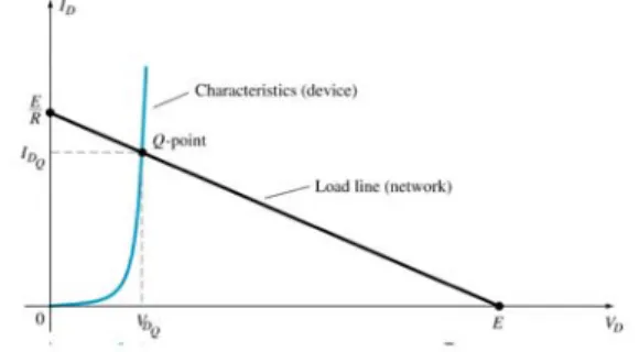
Figure 2 Solving Simultaneous Equations Graphically
Figure 2 shows two curves the first is the V-I characteristics of the diode and the second curve is a straight line that interests the first. The second curve (Line) is referred to as the
load line and has a slope of1/R (R is the load). The intercepts on the current and voltage axis are obtained by setting the current through the diode to zero, hence from Equation (1) the voltage across the diode isE. Similarly, by setting the voltage across the diode to zero the current through the diode is given byID =E/R. The point where the load line intercepts the V-I characteristics of the diode is the solution of the two simultaneous equations, and is referred to as the operating point or (quiescent) Q-point.
Figure 3 Example for a simple circuit with a 1 kΩ load.
The load-line for this circuit is drawn in Figure 4. The Q-point is situated at VD =0.78 Volts andID =9.25mA.
Figure 4 Load-line analyses for1 KΩ.
Let us now consider the same example using the approximate equivalent model for the silicon diode. The load –line analysis for same example using the approximate equivalent model for the diode is shown in Figure 5.
Figure 5 Load-line analyses for the example using approximate method.
The Q-point obtained from Figure 5 is obtained from reading the intercept of the two curves resulting in VD =0.7 Volts andID =9.25mA. Let us now change the load from
Ω K
load is shown in Figure 6. The corresponding intercept in this case is VD =0.7 Volts and the current through the diode isID =4.6mA.
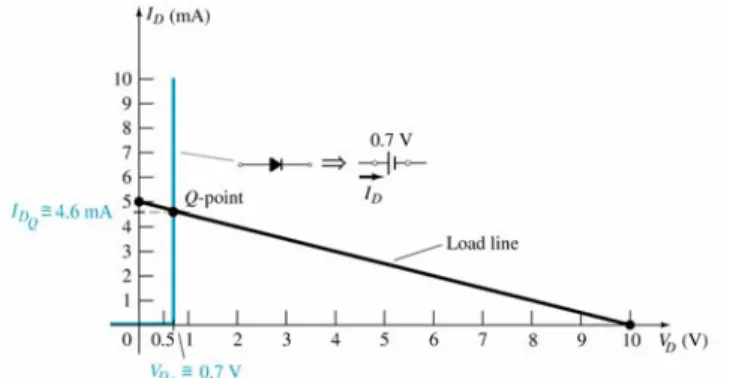
Figure 6 Load-line analyses for a load of 2 KΩ
The load –line analysis for same case using the approximate equivalent model is shown in Figure 7. The operating point for the diode in this case is VD =0.7 Volts and the current isID =4.6mA.
Figure 7 Load-line analysis for the example using approximate method.
As it can be seen from these examples the approximate diode method for load line analysis are close to the results obtained for the exact analysis. In the situations where the diodes are “turned on” the circuit can be analysed by replacing a silicon diode by a 0.7 Volt and a 0.3 Volts for Ge diodes.
3.0Series Diode Configuration Analysis
open circuit. (Note: For Ge diodes the offset voltage is 0.3 Volts and for GaAs it is 1.12 Volts.)
The approximate method can be used to analysis a number of series diode circuits. Each diode in the circuit has to be determined if it is in the “on” or “off” state. Once this is determined the approximate model is substituted in place of the diode and the remaining parameters can be calculated.
A diode is in the “on” state if the current established by the applied sources is such that its direction matches that of the arrow in the diode symbol, and VD =0.7V for silicon,
3 . 0 =
D
V V for germanium, and VD =1.2V for gallium arsenide.
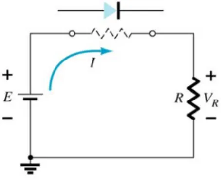
Consider the simple example of a series circuit as shown in Figure 8.
Figure 8 Simple Series Circuit
To determine if the diode is “on” or “off” replace the diode with a mentally imaginary resistance and analyse the circuit, as shown in Figure 9. We can see that in this case the current that flows is in the same direction as the diode. Hence the diode is “on”.
Figure 9 Diode replaced mentally imaginary resistance
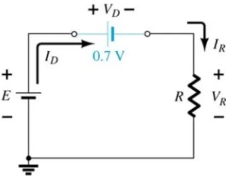
Figure 10 Equivalent Circuit for the diode circuit in Figure 8
It is now a simple procedure to use circuit theory to analyse the circuit to determine such parameters as current and voltage.
4.0Parallel Configurations
The method of analysis discussed in the above section can be extended to the analysis of parallel and series-parallel diode configurations. Consider the following examples.
Figure 11 Example of Parallel diodes.
If both these two diode are mentally replaced by resistors current would flow in the same direction as the diodes, hence both the diodes are turned on. Since the diodes are forward biased both are replaced by 0.7 V supplies opposing the direction of the current.
Figure 12 Equivalent Circuit for the circuit in Figure 11.
Simple circuit analysis indicated that the output voltage is 0.7 Volts. The current I1 is the current through the resistor, R.
mA k V V R V E R V
I R D 28.18
33 . 0 7 . 0 10 1 = Ω − = − = =
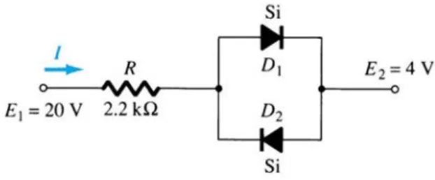
Let us now consider a second example as shown in Figure 13. This circuit consists of two diodes in parallel with these two diodes in series with a resistor.
Figure 13 Example of a series-parallel circuit
If we mentally replace the diodes by resistors we see that current will flow in the same direction as the doirection for the top diode, but the bottom diodes faces in the opposite direction to the current. Hence the top diode is turned “on” and the bottom diode is turned “off”. The top diode is replace by a 0.7 V supply opposing the flow of current and the bottom diode is replaced by an open circuit. The equivalent circuit is shown in Figure 14.
Figure 14 Equivalent Circuit for the circuit shown in Figure 13
The current flowing in the circuit is the same as the current flowing in the resistor. Hence
(
)
mA k R E E R VI R 6.9
2 . 2 ) 7 . 4 ( 20 7 . 0 2 1 = Ω − = + − = =
Note in the examples that we have considered the supply voltage is such that the voltage drop of 0.7 Volt will occur across the diode. If the supply voltage is small of the order of 0.5 Volts, the there is not enough “pressure” to turn the diodes on.
5.0 Conclusions
If the diodes are forward biased replace the diode with a supply voltage opposing the current flow. VD =0.7V for silicon, VD =0.3 V for germanium, and
2 . 1 =
D
V V for gallium arsenide.
If the diode is reverse biased then replace the diode with an open circuit.